Heartland VALUE Series Assembly Manual
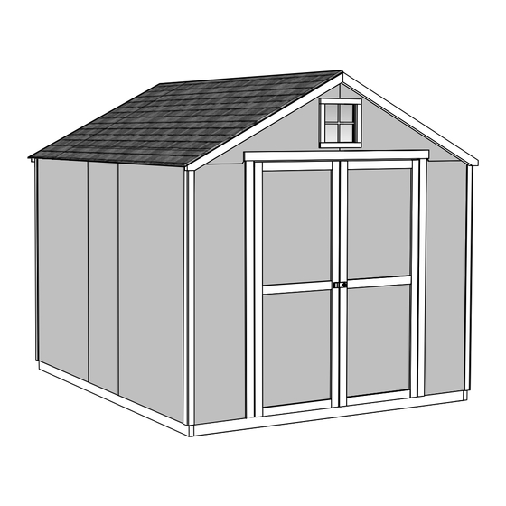
Belmont 8' x 10' (244 x 304,8 cm)
Hide thumbs
Also See for VALUE Series:
- Assembly manual (103 pages) ,
- Assembly manual (56 pages) ,
- Assembly manual (71 pages)
Advertisement
Quick Links
16806
STOP!
STOP!
Call Us First!
DO NOT RETURN TO STORE.
For immediate help with assembly or product information
call our toll free number:
1-800-577-9663
or email:
customerservice@backyardproductsllc.com
Our staff is ready to provide assistance
April through October M-F 8:00 AM to 4:30 PM EST
Saturday 8:30 AM to 4:30 PM EST
November through March M - F 8:00 AM to 5:00 PM EST
Advertisement

Related Manuals for Heartland VALUE Series


Summary of Contents for Heartland VALUE Series
- Page 1 16806 STOP! STOP! Call Us First! DO NOT RETURN TO STORE. For immediate help with assembly or product information call our toll free number: 1-800-577-9663 or email: customerservice@backyardproductsllc.com Our staff is ready to provide assistance April through October M-F 8:00 AM to 4:30 PM EST Saturday 8:30 AM to 4:30 PM EST November through March M - F 8:00 AM to 5:00 PM EST...
- Page 2 (This page intentionally left blank.)
-
Page 3: Assembly Manual
16806 12/01/2015 ASSEMBLY MANUAL A Backyard Products Company VALUE SERIES BELMONT 8' x 10' (244 x 304,8 cm) ACTUAL FLOOR SIZE: 8' x 9'- 8-1/2" (243,8 x 295,9 cm) KEEP THIS MANUAL FOR FUTURE REFERENCE I MPO RTA NT ! READ INSTRUCTIONS THOROUGHLY PRIOR TO BEGINNING ASSEMBLY. - Page 4 TOOLS Required Optional Phillips Tool Belt/ Utility Knife Screwdriver Nail Pouch Shingle Blades Tin Snips Drill / Driver (for drip edge) Caulk Gun 5/16" Drill Bit Chalk Line 1/8" Drill Bit ...
- Page 5 CONCRETE FOUNDATION If you choose to install your kit on a concrete slab refer to the diagram below. Treated Sill Plate Caulk between sill plate and concrete. 3-1/2" (8,9 cm) 4" (10,2 cm) Building Size Actual Floor Size 8' x 10' (243,8 x 304,8 cm) 8' x 9'-8-1/2"...
-
Page 6: Additional Materials
ADDITIONAL MATERIALS FOUNDATION OR FLOOR MATERIALS • This shed includes a complete wood floor frame system. It does not include floor panels. • This shed does not contain any leveling materials. • See the FLOOR LEVELING section on page 7 for recommended methods and suggested materials to properly level your floor, as this will vary depending on your specific site. -
Page 7: Parts List
PARTS IDENTIFICATION AND SIZES WOOD SIZE CONVERSION CHART Treated lumber is stamped: letters are stamped on some parts. Nominal Board Size Actual Size 2" x 4"....1-1/2" x 3-1/2" (3,8 x 8,9 cm) 1" x 4"....3/4" x 3-1/2" (1,9 x 8,9 cm) 2"... - Page 8 WALL PANELS & DOORS NOTE: Panel parts are not stamped. 3/8 x 23-7/8 x 72" (1 x 60,6 x 182,9 cm) LEFT DOOR RIGHT DOOR 3/8 x 48 x 72" 3/8 x 46-1/8 x 72" 3/8 x 20 x 72" (1 x 121,9 x 182,9 cm) (1 x 117,2 x 182,9 cm) (1 x 50,8 x 182,9 cm)
- Page 9 FLOOR LEVELING OPTIONS There are multiple ways to level your floor frame. Our recommended leveling method is shown below. Leveling materials are not included in this kit. PREFERRED METHOD - 4x4 TREATED RUNNERS 96" (243,8 cm) • 3" Screw angled into 4x4. •...
-
Page 10: Parts Required
STANDARD FLOOR FRAME PARTS REQUIRED: 2 x 4 x 24" (5,1 x 10,2 x 61 cm) 3" (7,6 cm) TREATED NOTE: 2 x 4 x 48" (5,1 x 10,2 x 122 cm) TREATED Look for Stamp. 2 x 4 x 68-1/2" (5,1 x 10,2 x 174 cm) TREATED 2 x 4 x 93"... - Page 11 LEVEL AND SQUARE FLOOR FRAME Before attaching fl oor decking, it is important to level and square the fl oor frame. A level and square fl oor frame is required to correctly construct your shed. BEGIN See page 7 for the preferred fl oor leveling method. Use level and check the frame is level before applying fl oor panels.
- Page 12 FLOOR PANELS (NOT INCLUDED) PARTS REQUIRED: 2" (5,1 cm) Floor Panels are not included. See Page 4 for panel sizes and quantities. 5/8 x 48 x 96" (1,6 x 121,9 x 243,8 cm) Ensure your floor frame is square by installing one panel and squaring frame.
- Page 13 FLOOR PANELS (NOT INCLUDED) PARTS REQUIRED: 2" (5,1 cm) 5/8 x 48 x 96" 5/8 x 20-1/2 x 96" (1,6 x 129,1 x 243,8 cm) (1,6 x 52,11 x 243,8 cm) Continue installing panels with rough side up (painted grid lines). Use grid lines on panel for 2"...
- Page 14 IMPORTANT! I M P O R T A N T ! Check the floor frame is level after installing floor panels. Re-level if needed. • The floor should be used as a stable work surface for wall construction. HINT: • Organize your assembly procedure during the build process to avoid over-handling of the walls.
- Page 15 EAVE WALL FRAMING PARTS REQUIRED: 3" (7,6 cm) 2 x 3 x 46-1/4" (5,1 x 7,6 x 117,5 cm) 2 x 3 x 66-1/2" (5,1 x 7,6 x 168,9 cm 2 x 3 x 70-1/4" (5,1 x 7,6 x 178,4 cm) BEGIN Orient parts on edge on fl oor.
- Page 16 EAVE WALL PANELS PARTS REQUIRED: 2" (5,1 cm) 3/4" 2x3" GAUGE BLOCK GAUGE BLOCK 3/8 x 46-1/8 x 72" (1 x 117,2 x 182,8 cm) Ensure your wall frame is square by installing one panel and squaring frame. BEGIN Place a 46-1/8 x 72" panel onto wall frame with primed side up as shown. Locate the panel 1-1/2"...
- Page 17 EAVE WALL PANELS PARTS REQUIRED: 2" (5,1 cm) 2x3" GAUGE BLOCK 3/8 x 46-1/8 x 72" 3/8 x 23-7/8 x 72" (1 x 117,2 x 182,8 cm) (1 x 60,6 x 182,8 cm) Place 23-7/8" panel on frame as shown with primed side facing up fl ush with fi rst panel.
- Page 18 BACK WALL FRAME PARTS REQUIRED: 3" (7,6 cm) 2 x 3 x 34" (5,1 x 7,6 x 86,4 cm) 2 x 3 x 91 " (5,1 x 7,6 x 231,1 cm) BEGIN Center flush on CI on edge on floor as shown (Fig. A). Nail using two 3"...
- Page 19 BACK WALL FRAME PARTS REQUIRED: 3" (7,6 cm) 3" (7,6 cm) 2 x 3 x 34" (5,1 x 7,6 x 86,4 cm) 2 x 3 x 96" (5,1 x 7,6 x 243,8 cm) Center fl ush on PS on fl at using a gusset as a temporary spacer. on CI on edge on fl oor as shown.
- Page 20 BACK WALL PANELS PARTS REQUIRED: 2" (5,1 cm) 3/8 x 48 x 72" (1 x 121,9 x 182,9 cm) BEGIN Place LEFT panel on back frame as shown with primed side facing up. Secure Using 2" nails 6" apart on edges and 12" apart inside panel. For squareness maintain flush and 3/4"...
- Page 21 BACK WALL PANELS PARTS REQUIRED: 2" (5,1 cm) 3/8 x 48 x 72" (1 x 121,9 x 182,9 cm) Place RIGHT panel on back frame as shown with primed side facing up and fl ush to panel. Ensure 34" (86,4 cm) between PT and PS. Secure Using 2"...
-
Page 22: Front Wall
FRONT WALL PARTS REQUIRED: 2" (5,1 cm) 2 x 3 x 17-1/2" (5,1 x 7,6 x 44,5 cm) 3/8 x 20 x 72" (1 x 50,8 x 182,9 cm) TEMPORARY SUPPORT 2 x 3 x 96" (5,1 x 7,6 x 243,8 cm) BEGIN Orient PT on edge and place LEFT panel on PT as shown with primed side facing up. - Page 23 FRONT WALL PARTS REQUIRED: 2" (5,1 cm) 2 x 3 x 17-1/2" (5,1 x 7,6 x 44,5 cm) BEGIN Position BV on edge, 2-1/2" from outside edge and 1" from bottom edge of LEFT wall panel. (Fig A.) Nail BV to wall panel using (3) 2" Nails. Repeat step 1-2 for RIGHT wall panel.
- Page 24 FRONT WALL TOP PLATE PARTS REQUIRED: 3" (7,6 cm) GUSSET 2 x 3 x 66-1/2" (5,1 x 7,6 x 168,9 cm) TEMPORARY SPACER BEGIN Center FZ on PT on flat, flush to front wall panel (Fig. A). Secure using five 3" screws on angle spaced evenly. Mark center of door opening for later alignment.
- Page 25 EAVE WALLS INSTALLATION PARTS REQUIRED (TEMPORARY): 3" (7,6 cm) 1-1/4 x 2-1/2 x 69" (3,2 x 7,6 x 175,3 cm) 3" (7,6 cm) TEMPORARY SUPPORT 2" (5,1 cm) BEGIN Center side wall assembly on the 116-1/2" (295,9 cm) fl oor dimension. Ensure 1-1/2"...
-
Page 26: Back Wall Installation
BACK WALL INSTALLATION PARTS REQUIRED: 3" (7,6 cm) 1-1/2" (3,8 cm) 2" (5,1 cm) 3" (7,6 cm) 2" (5,1 cm) It is important to secure the back wall in the following order: BEGIN Set back wall on side wall top plate and secure using two 3" screws on each side (Fig A). Nail lower edge of panels to fl oor frame using 2"... - Page 27 FRONT WALL INSTALLATION PARTS REQUIRED: 3" (7,6 cm) 2" (5,1 cm) 3" (7,6 cm) 1-1/2" (3,8 cm) It is important to secure the front wall in the following order: BEGIN Secure front wall top plate to side walls using two 3" screws (Fig. A, B). (Fig.
- Page 28 RAFTERS PARTS REQUIRED: 2" (5,1 cm) 6 x 24" (15,2 x 61 cm) 1-1/4 x 2-1/2 x 69" (3,2 x 7,6 x 175,3 cm) TEMPORARY SUPPORT 2 x 4 x 54-1/16" (5,1 x 10,2 x 129,8 cm) BEGIN You will build FOUR assemblies; Place two rafter-halves WI in the corner of back and side walls.
- Page 29 RAFTERS PARTS REQUIRED: 3" (7,6 cm) PRE-ASSEMBLED BEGIN Locate rafters directly over the wall studs. Ensure you have the measurements shown. Screw through panel into end of rafter with 3" screw (Fig. A, Fig. B). (Fig. A, Fig. B). Secure with 3" screw angled from bottom of top plate into rafter FINISH NOTE: Measurements from outside of panels...
- Page 30 BACK WALL GABLE PANELS PARTS REQUIRED: 1-1/2" (3,8 cm) 2 x 3 x 23-7/8" (5,1 x 7,6 x 60,6 cm) BEGIN Place LW on fl at on fl oor. Place RIGHT gable panel primed side up, centered on LW with a 3/4" overhang on bottom.
- Page 31 BACK WALL GABLE PANELS PARTS REQUIRED: 3" (7,6 cm) 2" (5,1 cm) PRE-ASSEMBLED BEGIN Place gable assembly centered on back wall top plate overlapping the back wall panels 3/4" (Fig. A). Nail assembly to back wall panels using 2" nails 6" apart. Screw LW to top plate using two 3"...
- Page 32 FRONT WALL GABLE PANELS PARTS REQUIRED: 1-1/2" (3,8 cm) 2 x 3 x 11-7/8" (5,1 x 7,6 x 30,2 cm) BEGIN Place DQ on fl at on fl oor as shown. Place RIGHT gable panel primed side up, centered on top DQ as shown. Secure using two 1-1/2"...
- Page 33 WINDOW INSTALL PARTS REQUIRED: 1" (2,5 cm) 1/8" (0,3 cm)Drill Bit BEGIN Center window in window opening as shown. Make sure both Center window in window opening as shown.Make sure frame is at an measurements are equal from bottom. equal distance from bottom of panel (Fig. A). Secure window to DQ using one screw in top and bottom (Fig.
- Page 34 WINDOW INSTALL WINDOW INSTALL ARTS REQUIRED: PARTS REQUIRED: 1-5/8" (4,1 cm) 1/2" (1,3 cm) 1 x 2 x 11" (2,5 x 5,1 x 27,9 cm) 1 x 2 x 11" (2,5 x 5,1 x 27,9 cm) 1/2" (1,3 cm) NOTE POINT 1 x 2 x 14"...
- Page 35 FRONT WALL GABLE PANELS PARTS REQUIRED: WINDOW INSTALL 3" (7,6 cm) PARTS REQUIRED: 2" (5,1 cm) 1/8" (0,3 cm)Drill Bit PRE-ASSEMBLED BEGIN Center window in window opening as shown. Make sure both measurements are equal from bottom. BEGIN Place gable assembly centered on front wall top plate overlapping front wall panels.
- Page 36 GABLE TRIM PARTS REQUIRED: 1-1/4" (3,2 cm) 2 x 3 x 55-3/4" (5,1 x 7,6 x 141,6 cm) ¸ BEGIN Install front gable trim WX fl ush to top edge of panel and fl ush at peak (Fig. A) as shown. Attach trim to wall using 1-1/4"...
- Page 37 ROOF PANELS PARTS REQUIRED: 2" (5,1 cm) 7/16 x 48 x 96" (1,1 x 121,9 x 243,8 cm) 3/4" GAUGE BLOCK Roof panels may cause serious injury until securely fastened. You must square the roof by attaching one panel first. You will use the panels’ long edge as a lever to bring your roof into square.
- Page 38 ROOF PANELS PARTS REQUIRED: 2" (5,1 cm) 7/16 x 7-7/8 x 96" (1,1 x 20 x 243,8 cm) Keep spacing between the center of the rafters at the lower edge of the panel and secure with one 2" nail into each rafter (Fig.
- Page 39 ROOF PANELS PARTS REQUIRED: 2" (5,1 cm) 7/16 x 23-7/8 x 55-7/8" (1,1 x 60,6 x 141,9 cm) Attach the 23-7/8 x 55-7/8" roof panel fl ush to the installed panels and with a 1/2" measurement at the gable trim (Fig. H). Nail the roof panel using 2"...
- Page 40 CORNER TRIM PARTS REQUIRED: 2" (5,1 cm) 3/8 x 1-3/4 x 71-1/4" (1 x 4,4 x 181 cm) 3/8 x 1-3/4 x 71-3/4" (1 x 4,4 x 182,2 cm) ¸ BEGIN Attach 71-3/4" trim fl ush to back of gable trim, bottom of roof panel and trim (Fig. A) using 2"...
- Page 41 DOORS PARTS REQUIRED: 3" (7,6 cm) 1-1/4 x 2-1/2 x 69" (3,2 x 7,6 x 175,3 cm) 1-1/4" (3,2 cm) TEMPORARY SUPPORT HINT: Look for 3/8" SPACER attached to doors. x1 GAA 1 x 3 x 5" (2,5 x 7,6 x 12,7 cm) Left Door Right Door BEGIN...
- Page 42 DOORS PARTS REQUIRED: 3" (7,6 cm) 1-1/4 x 2-1/2 x 69" (3,2 x 7,6 x 175,3 cm) TEMPORARY SUPPORT Attach temporary support OO as a ledger board fl ush under wall panels for doors to rest on, using three 3" screws (Fig. A) . 72"...
- Page 43 DOORS PARTS REQUIRED: 2" (5 cm) x8 3/4" (1,9 cm) x10 3/4" (1,9 cm) x52 Bagged separately / special coating 19/32 x 3 x 63" (1,5 x 7,6 x 160 cm) 19/32 x 2-1/2 x 23" (1,5 x 6,3 x 58,4 cm) 56"...
- Page 44 DOOR WEATHERSTRIP PARTS REQUIRED: 2" (5 cm) 1-1/4 x 2-1/2 x 69" (3,2 x 7,6 x 175,3 cm) BEGIN With left door closed, center a weatherstrip OO vertically on the left door in the door opening (Fig. A). OO will offset the left door 1" OUT past the door trim 1"...
-
Page 45: Door Hardware
DOOR HARDWARE DOOR PARTS REQUIRED: 1" (2,5 cm) 5/16" (0,8 cm) Drill Bit 3/4" (1,9 cm) BEGIN Place bolt onto OO in open position with bolt end 1/4" down from frame. Bolt is open when loop is contacting base (Fig A) . Mark and pre-drill holes for screws. - Page 46 PAINT & CAULK - NOT INCLUDED - • Use acrylic latex caulk that is paintable. Caulk at all horizontal and vertical seams, between the trim and walls, and all around the door trim. • Use a high quality exterior acrylic latex paint. When painting your building, there are a few key areas that can be easily overlooked that must be painted: •...
- Page 47 SHINGLES - NOT INCLUDED - • Follow directions provided by manufacturer and these instructions. Familiarize yourself with a 3-Tab Shingle. Notch Notch SHINGLE NAIL PATTERN 1/2" 1" Sealing Strip 1" (1,3 cm) (2,5 cm) (2,5 cm) Half A Rain Slot Full Rain Slot NAILS NEVER DRIVE FASTENERS INTO OR ABOVE SEALING STRIPS.
- Page 48 SHINGLES continued... Beginning at front of shed, install first row of shingles with notch at 1" past roof edge or flush with drip edge. Roof Deck FRONT OF BACK OF SHED SHED 1" (2,5 cm) Flush with starter row. Notch - or - Drip Edge Flush with starter row.
- Page 49 SHINGLES continued... Continue installing rows of shingles to the peak. At the peak make sure there is a maximum of 5" or less to the rain slot, as shown below. If shingles overlap at ridge cut to peak with a utility knife. 5"...
- Page 50 SHINGLES - RIDGE CAP • You will finish off the top of the roof with a ridge cap made from shingles. BEGIN Cut shingles into THREE pieces. Hint: Use cut-off pieces first. 2" 2" (5,1 cm) (5,1 cm) 2" 2" 2"...
- Page 51 SHINGLES - RIDGE CAP continued... Continue installing ridge cap to back of roof. Make sure there is 4" between the shingle-color and edge of shingles. Trim cap off fl ush to shingles When you have 4" minimum of shingle color cut one piece to cap your roof. Install fl ush to shingles.
- Page 52 All accessories, hardware and metal components are warranted for 2 years. All Oriented Strand Board (OSB) is warranted for 2 years Siding and Trim is warranted for: 10 years: Value Series / Solar Shed 12 years: Classic Series / Architectural Series 15 years: Big Buildings Solar Shed windows are warranted for 1 year.
Need help?
Do you have a question about the VALUE Series and is the answer not in the manual?
Questions and answers