Mitsubishi Electric MELSERVO-J3 Series Instruction Manual
Hide thumbs
Also See for MELSERVO-J3 Series:
- Manual (668 pages) ,
- Handbook (590 pages) ,
- Instruction manual (408 pages)

Related Manuals for Mitsubishi Electric MELSERVO-J3 Series


Summary of Contents for Mitsubishi Electric MELSERVO-J3 Series
- Page 1 General-Purpose AC Servo Series Built-in Positioning Function MODEL MR-J3- T SERVO AMPLIFIER INSTRUCTION MANUAL (CC-Link)
- Page 2 Safety Instructions Always read these instructions before using the equipment. To use the equipment correctly, do not attempt to install, operate, maintain or inspect the servo amplifier and servo motor until you have read through this Instruction Manual, Installation guide, Servo motor Instruction Manual (Vol.2) and appended documents carefully and can use the equipment correctly.
- Page 3 1. To prevent electric shock, note the following WARNING Before wiring or inspection, turn off the power and wait for 15 minutes or more until the charge lamp turns off. Then, confirm that the voltage between P( ) and N( ) is safe with a voltage tester and others. Otherwise, an electric shock may occur.
- Page 4 3. To prevent injury, note the follow CAUTION Only the voltage specified in the Instruction Manual should be applied to each terminal, Otherwise, a burst, damage, etc. may occur. Connect the terminals correctly to prevent a burst, damage, etc. Ensure that polarity ( , ) is correct.
- Page 5 CAUTION When you keep or use the equipment, please fulfill the following environmental conditions. Environment Item Servo amplifier Servo motor 0 to 55 (non-freezing) 0 to 40 (non-freezing) In operation 32 to 131 (non-freezing) 32 to 104 (non-freezing) Ambient temperature 20 to 65 (non-freezing) 15 to 70 (non-freezing) In storage...
- Page 6 (2) Wiring CAUTION Wire the equipment correctly and securely. Otherwise, the servo motor may operate unexpectedly. Do not install a power capacitor, surge killer or radio noise filter (FR-BIF-(H) option) between the servo motor and servo amplifier. To avoid a malfunction, connect the wires to the correct phase terminals (U, V, and W) of the servo amplifier and servo motor.
- Page 7 (4) Usage CAUTION Provide an external emergency stop circuit to ensure that operation can be stopped and power switched off immediately. Any person who is involved in disassembly and repair should be fully competent to do the work. Before resetting an alarm, make sure that the run signal of the servo amplifier is off to prevent an accident.
- Page 8 (6) Maintenance, inspection and parts replacement CAUTION With age, the electrolytic capacitor of the servo amplifier will deteriorate. To prevent a secondary accident due to a fault, it is recommended to replace the electrolytic capacitor every 10 years when used in general environment.
- Page 9 General-Purpose AC servo MR-J3-T for the first time. Always purchase them and use the MR-J3-T safely. Relevant manuals Manual name Manual No. MELSERVO-J3 Series Instructions and Cautions for Safe Use of AC Servos IB(NA)0300077 MELSERVO Servo Motor Instruction Manual (Vol.2) SH(NA)030041 EMC Installation Guidelines IB(NA)67310 <<About the wires used for wiring>>...
-
Page 10: Table Of Contents
CONTENTS 1. FUNCTIONS AND CONFIGURATION 1 - 1 to 1 -36 1.1 Introduction ............................... 1 - 1 1.1.1 Features of CC-Link communication functions ................1 - 1 1.1.2 Function block diagram ........................1 - 2 1.1.3 System configuration ......................... 1 - 5 1.2 Servo amplifier standard specifications .................... - Page 11 3.6.3 Remote register-based position/speed setting ................3 -38 3.7 Function-by-function programming examples ..................3 -41 3.7.1 System configuration example ......................3 -41 3.7.2 Reading the servo amplifier status ....................3 -44 3.7.3 Writing the operation commands ..................... 3 -45 3.7.4 Reading the data ..........................3 -46 3.7.5 Writing the data ..........................
- Page 12 5.1.1 Startup procedure ..........................5 - 1 5.1.2 Wiring check ............................5 - 2 5.1.3 Surrounding environment ........................5 - 3 5.2 Startup ..............................5 - 4 5.2.1 Power on and off procedures ......................5 - 4 5.2.2 Stop ..............................5 - 4 5.2.3 Test operation............................
- Page 13 6.1.8 Electronic gear........................... 6 - 6 6.1.9 Auto tuning ............................6 - 9 6.1.10 In-position range ..........................6 -10 6.1.11 Torque limit ............................. 6 -11 6.1.12 Selection of servo motor rotation direction ..................6 -11 6.1.13 Encoder output pulse ........................6 -12 6.2 Gain/filter parameters (No.PB ) ......................
- Page 14 8.5 Display ..............................8 - 7 8.5.1 Outline of screen transition ....................... 8 - 7 8.5.2 MR-PRU03 parameter unit setting ....................8 - 8 8.5.3 Monitor mode (status display) ......................8 - 9 8.5.4 Alarm/diagnostic mode ........................8 -11 8.5.5 Parameter mode ..........................8 -13 8.5.6 Point table mode ..........................
- Page 15 12.1 Servo amplifier ............................12- 1 12.2 Connector ............................. 12-10 13. CHARACTERISTICS 13- 1 to 13-12 13.1 Overload protection characteristics ...................... 13- 1 13.2 Power supply equipment capacity and generated loss ............... 13- 3 13.3 Dynamic brake characteristics ......................13- 6 13.3.1 Dynamic brake operation .......................
- Page 16 15.3.3 Error codes ............................. 15- 7 15.3.4 Checksum ............................15- 7 15.3.5 Time-out processing ........................15- 7 15.3.6 Retry processing ..........................15- 8 15.3.7 Initialization ............................. 15- 8 15.3.8 Communication procedure example ....................15- 9 15.4 Command and data No. list ......................... 15-10 15.4.1 Read commands ...........................
- Page 17 16.6 Servo amplifier display ......................... 16-36 16.7 Automatic operation mode ........................16-38 16.7.1 What is automatic operation mode? ..................... 16-38 16.7.2 Automatic operation mode 1 (Rotation direction specifying indexer) .......... 16-39 16.7.3 Automatic operation mode 2 (Shortest rotating indexer) ............. 16-49 16.8 Manual operation mode ........................
- Page 18 17.5 Startup ..............................17-28 17.5.1 Power on and off procedures......................17-28 17.5.2 Stop..............................17-28 17.5.3 Test operation ..........................17-29 17.5.4 Parameter setting .......................... 17-30 17.5.5 Point table setting .......................... 17-31 17.5.6 Actual operation ..........................17-31 17.6 Servo amplifier display ......................... 17-32 17.7 Speed control operation ........................
- Page 19 MEMO...
-
Page 20: Functions And Configuration
1. FUNCTIONS AND CONFIGURATION 1. FUNCTIONS AND CONFIGURATION 1.1 Introduction The MR-J3- T CC-Link compatible servo amplifier can support the CC-Link communication functions. Up to 42 axes of servo amplifiers can be controlled/monitored from the programmable controller side. As the servo, it has the function to perform positioning operation by merely setting the position data (target positions), servo motor speeds, acceleration and deceleration time constants, etc. -
Page 21: Function Block Diagram
1. FUNCTIONS AND CONFIGURATION 1.1.2 Function block diagram The function block diagram of this servo is shown below. (1) MR-J3-350T or less MR-J3-200T4 or less Power factor improving DC Regenerative reactor option Servo amplifier Servo motor P( ) N( ) Diode (Note 1) stack... - Page 22 1. FUNCTIONS AND CONFIGURATION (2) MR-J3-350T4 MR-J3-500T(4) MR-J3-700T(4) Power factor improving DC Regenerative reactor option Servo motor Servo amplifier Diode stack Relay MCCB (Note 1) Current Power detector supply Regene- CHARGE rative lamp Cooling fan Dynamic brake circuit Electro- Control 24VDC magnetic circuit...
- Page 23 1. FUNCTIONS AND CONFIGURATION (3) MR-J3-11KT(4) to 22KT(4) Power factor (Note 3) improving DC Regenerative reactor option External dynamic brake (optional) Servo amplifier Servo motor Diode Thyristor stack MCCB (Note 1) Current Power detector supply CHARGE Regene- rative lamp Cooling fan Electro- Control 24VDC...
-
Page 24: System Configuration
1. FUNCTIONS AND CONFIGURATION 1.1.3 System configuration This section provides operations using this servo. Use of CC-Link enables you to freely configure any system from a single-axis system to an up to 42-axis system. Set the following values to the point table. Name Setting range Unit... - Page 25 1. FUNCTIONS AND CONFIGURATION (2) Operation using CC-Link communication functions and external input signals (a) Operation Using parameter No.PD06 to PD08 and parameter No.PD12, PD14, input devices can be assigned to the external input devices of CN1A and CN1B. The signals assigned to the external input signals cannot be used with the CC-Link communication functions.
-
Page 26: Servo Amplifier Standard Specifications
1. FUNCTIONS AND CONFIGURATION 1.2 Servo amplifier standard specifications (1) 200V class, 100V class Servo amplifier MR-J3- 10T 20T 40T 70T 100T 200TN 350T 500T 700T 11KT 15KT 22KT 10T1 20T1 40T1 Item Rated voltage 3-phase 170VAC Output Rated current [A] 1.1 1.5 2.8 5.8 6.0 11.0 17.0 28.0 37.0 68.0 87.0 126.0 1.1... - Page 27 1. FUNCTIONS AND CONFIGURATION Servo amplifier MR-J3- 10T 20T 40T 60T 70T 100T 200TN 350T 500T 700T 11KT 15KT 22KT 10T1 20T1 40T1 Item Home position return is made starting with Z-phase pulse after passage of proximity dog. Home position address may be set. Home position shift distance may be set. Home position return Dog type direction may be selected.
- Page 28 1. FUNCTIONS AND CONFIGURATION Servo amplifier MR-J3- 10T 20T 40T 60T 70T 100T 200TN 350T 500T 700T 11KT 15KT 22KT 10T1 20T1 40T1 Item 0 to 55 (non-freezing) In operation 32 to 131 (non-freezing) Ambient temperature 20 to 65 (non-freezing) In storage 4 to 149 (non-freezing) Ambient...
- Page 29 1. FUNCTIONS AND CONFIGURATION (2) 400V class Servo amplifier MR-J3- 60T4 100T4 200T4 350T4 500T4 700T4 11KT4 15KT4 22KT4 Item Rated voltage 3-phase 323VAC Output Rated current 14.0 17.0 32.0 41.0 63.0 Voltage/frequency 3-phase 380 to 480VAC, 50/60Hz Rated current 10.8 14.4 23.1...
- Page 30 1. FUNCTIONS AND CONFIGURATION Servo amplifier MR-J3- 60T4 100T4 200T4 350T4 500T4 700T4 11KT4 15KT4 22KT4 Item Home position return is made starting with Z-phase pulse after passage of proximity dog. Home position address may be set. Home position shift distance may be set. Home position return Dog type direction may be selected.
- Page 31 1. FUNCTIONS AND CONFIGURATION Servo amplifier MR-J3- 60T4 100T4 200T4 350T4 500T4 700T4 11KT4 15KT4 22KT4 Item 0 to 55 (non-freezing) In operation 32 to 131 (non-freezing) Ambient temperature 20 to 65 (non-freezing) In storage 4 to 149 (non-freezing) In operation Ambient 90%RH or less (non-condensing) humidity...
-
Page 32: Function List
1. FUNCTIONS AND CONFIGURATION 1.3 Function list The following table lists the functions of this servo. For details of the functions, refer to the reference field. Function Description Reference Select the required ones from among 31 preset point tables and perform operation in Positioning by automatic accordance with the set values. -
Page 33: Model Code Definition
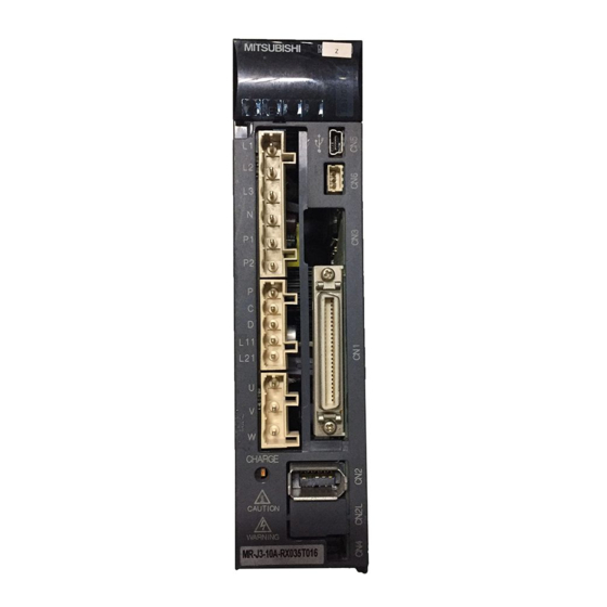
0.9A 3PH+1PH200-230V 50Hz Applicable power supply 3PH+1PH200-230V 60Hz 1.3A 1PH200-230V 50Hz/60Hz Rated output current OUTPUT 170V 0-360Hz 1.1A SERIAL A18001050 Serial number KCC-REI-MEK-TC300A *** G51 MITSUBISHI ELECTRIC CORPORATION KC certification number MADE IN JAPAN Country of origin 1 - 14... -
Page 34: Combination With Servo Motor
1. FUNCTIONS AND CONFIGURATION (2) Model The following describes what each block of a model name indicates. Not all combinations of the symbols are available. Series Special specification Supplied Symbol Special specification regenerative Rated output resistor 11k to 22kW servo amplifiers Symbol Rated output [kW] (Excluding the servo amplifiers... - Page 35 1. FUNCTIONS AND CONFIGURATION Servo motors Servo amplifier HA-LP HF-JP 1000r/min 1500r/min 2000r/min 1500r/min 3000r/min MR-J3-60T MR-J3-70T MR-J3-100T 153 203 MR-J3-200TN MR-J3-350T MR-J3-500T 11K1M (Note) MR-J3-700T 701M 801 12K1 11K1M 15K1M (Note) MR-J3-11KT 11K2 MR-J3-15KT 15K1 15K1M 15K2 20K1 25K1 22K1M MR-J3-22KT 22K2...
-
Page 36: Structure
1. FUNCTIONS AND CONFIGURATION 1.6 Structure 1.6.1 Parts identification (1) MR-J3-100T or less Detailed Name/Application explanation Display Section 5.3 The 3-digit, seven-segment LED shows the servo Chapter 11 status and alarm number. Baud rate switch (MODE) MODE Section 3.2.4 Select the CC-Link communication baud rate. Station number switches (STATION NO.) Set the station number of the servo amplifier. - Page 37 1. FUNCTIONS AND CONFIGURATION (2) MR-J3-200TN MR-J3-200T4 or less Detailed Name/Application explanation Display Section 5.3 The 3-digit, seven-segment LED shows the servo Chapter 11 status and alarm number. Baud rate switch (MODE) MODE Section 3.2.4 Select the CC-Link communication baud rate. Station number switches (STATION NO.) Set the station number of the servo amplifier.
- Page 38 1. FUNCTIONS AND CONFIGURATION (3) MR-J3-350T Detailed Name/Application explanation Display Section 5.3 The 3-digit, seven-segment LED shows the servo status and alarm number. Chapter 11 Baud rate switch (MODE) MODE Section 3.2.4 Select the CC-Link communication baud rate. Station number switches (STATION NO.) Set the station number of the servo amplifier.
- Page 39 1. FUNCTIONS AND CONFIGURATION (4) MR-J3-350T4 MR-J3-500T(4) POINT The servo amplifier is shown without the front cover. For removal of the front cover, refer to section 1.6.2. Detailed Name/Application explanation Display Section 5.3 The 3-digit, seven-segment LED shows the servo Chapter 11 status and alarm number.
- Page 40 1. FUNCTIONS AND CONFIGURATION (5) MR-J3-700T(4) POINT The servo amplifier is shown without the front cover. For removal of the front cover, refer to section 1.6.2. Detailed Name/Application explanation Display Section 5.3 The 3-digit, seven-segment LED shows the servo Chapter 11 status and alarm number.
- Page 41 1. FUNCTIONS AND CONFIGURATION (6) MR-J3-11KT(4) to MR-J3-22KT(4) POINT The servo amplifier is shown without the front cover. For removal of the front cover, refer to section 1.6.2. Detailed Name/Application explanation Display Section 5.3 The 3-digit, seven-segment LED shows the servo Chapter 11 status and alarm number.
-
Page 42: Removal And Reinstallation Of The
1. FUNCTIONS AND CONFIGURATION 1.6.2 Removal and reinstallation of the front cover Before removing or installing the front cover, turn off the power and wait for 15 minutes or more until the charge lamp turns off. Then, confirm that the voltage between P( ) and N( ) is safe with a voltage tester and others. - Page 43 1. FUNCTIONS AND CONFIGURATION Reinstallation of the front cover Front cover setting tab Insert the front cover setting tabs into the sockets of Pull up the front cover, supporting at point a) . servo amplifier (2 places). Setting tab Push the setting tabs until they click. 1 - 24...
- Page 44 1. FUNCTIONS AND CONFIGURATION (2) For MR-J3-11KT(4) to MR-J3-22KT(4) Removal of the front cover 1) Press the removing knob on the lower side of the 3) Pull it to remove the front cover. front cover ( a) and b) ) and release the installation hook.
-
Page 45: Configuration Including Auxiliary Equipment
1. FUNCTIONS AND CONFIGURATION 1.7 Configuration including auxiliary equipment POINT Equipment other than the servo amplifier and servo motor are optional or recommended products. (1) MR-J3-100T or less (a) For 3-phase or 1-phase 200V to 230VAC R S T (Note 3) Power supply MR Configurator Personal... - Page 46 1. FUNCTIONS AND CONFIGURATION (b) For 1-phase 100V to 120VAC (Note 3) Power supply MR Configurator Personal computer Molded-case circuit breaker (MCCB) Servo amplifier Magnetic contactor (MC) Power factor improving DC CC-Link reactor (FR-BEL) (Note 2) Line noise filter (FR-BSF01) I/O signal (Note 1) Battery...
- Page 47 1. FUNCTIONS AND CONFIGURATION (2) MR-J3-60T4 MR-J3-100T4 R S T (Note 3) Power supply Personal MR Configurator computer Molded-case circuit breaker (MCCB) Magnetic Servo amplifier contactor (MC) (Note 2) CC-Link Line noise filter (FR-BSF01) (Note 2) Power factor I/O signal improving DC reactor (FR-BEL-H)
- Page 48 1. FUNCTIONS AND CONFIGURATION (3) MR-J3-200TN MR-J3-200T4 (Note 3) R S T Power supply Molded-case circuit breaker (MCCB) Personal MR Configurator computer Magnetic contactor (MC) (Note 2) Line noise filter (FR-BSF01) Servo amplifier (Note 2) Power factor improving DC reactor (FR-BEL-(H)) CC-Link (Note 4)
- Page 49 1. FUNCTIONS AND CONFIGURATION (4) MR-J3-350T R S T (Note 3) Power supply Molded-case circuit breaker (MCCB) Magnetic contactor MR Configurator Personal (MC) computer (Note 2) Servo amplifier Line noise filter (FR-BLF) (Note 2) Power factor improving DC reactor (FR-BEL) CC-Link Regenerative option I/O signal...
- Page 50 1. FUNCTIONS AND CONFIGURATION (5) MR-J3-350T4 MR-J3-500T(4) R S T (Note 3) Power supply MR Configurator Personal computer Molded-case circuit breaker (MCCB) Servo amplifier Magnetic contactor (MC) CC-Link (Note 2) (Note 1) Battery MR-J3BAT Line noise filter (FR-BLF) I/O signal (Note 2) Power factor improving DC...
- Page 51 1. FUNCTIONS AND CONFIGURATION (6) MR-J3-700T(4) (Note 3) R S T Power supply MR Configurator Personal computer Molded-case circuit breaker (MCCB) Servo amplifier Magnetic contactor (MC) CC-Link (Note 1) Battery (Note 2) MR-J3BAT Line noise filter (FR-BLF) I/O signal (Note 2) Power factor improving DC reactor...
- Page 52 1. FUNCTIONS AND CONFIGURATION (7) MR-J3-11KT(4) to MR-J3-22KT(4) R S T (Note 3) Power supply Personal MR Configurator computer Molded-case circuit breaker (MCCB) Servo amplifier Magnetic contactor (MC) (Note 2) Line noise CC-Link filter (Note 1) (FR-BLF) Battery MR-J3BAT I/O signal (Note 2) Power factor improving DC...
-
Page 53: Selection Of Operation Method
1. FUNCTIONS AND CONFIGURATION 1.8 Selection of operation method Using the CC-Link communication functions, this servo enables a wide variety of operation methods. The operation method changes depending on the input device, parameter and point table setting. The flow of the operation method that changes depending on the device and parameter setting status is shown in the chart for your reference. - Page 54 1. FUNCTIONS AND CONFIGURATION Reference Main description Positioning is started by Positioning operation is Point table Section 3.8.2 making the start signal executed once with auxiliary function Section valid after selection of position data handled as 5.4.2 (1) the point table with the absolute value.
- Page 55 1. FUNCTIONS AND CONFIGURATION MEMO 1 - 36...
-
Page 56: Installation
2. INSTALLATION 2. INSTALLATION Stacking in excess of the limited number of products is not allowed. Install the equipment on incombustible material. Installing them directly or close to combustibles will lead to a fire. Install the servo amplifier and the servo motor in a load-bearing place in accordance with the Instruction Manual. - Page 57 2. INSTALLATION (1) 7kW or less (a) Installation of one servo amplifier Control box Control box 40mm or more Wiring allowance Servo amplifier 80mm or more 10mm 10mm or more or more Bottom 40mm or more (b) Installation of two or more servo amplifiers POINT Close mounting is available for the servo amplifier of under 3.5kW for 200V class and 400W for 100V class.
- Page 58 2. INSTALLATION (2) 11k to 22kW (a) Installation of one servo amplifier Control box Control box 40mm or more Servo amplifier Wiring allowance 80mm 10mm 10mm or more or more Bottom 120mm or more (b) Installation of two or more servo amplifiers Leave a large clearance between the top of the servo amplifier and the internal surface of the control box, and install a cooling fan to prevent the internal temperature of the control box from exceeding the environmental conditions.
-
Page 59: Keep Out Foreign Materials
2. INSTALLATION 2.2 Keep out foreign materials (1) When installing the unit in a control box, prevent drill chips and wire fragments from entering the servo amplifier. (2) Prevent oil, water, metallic dust, etc. from entering the servo amplifier through openings in the control box or a cooling fan installed on the ceiling. -
Page 60: Parts Having Service Lives
2. INSTALLATION (6) Check for unusual noise generated from the servo amplifier. 2.5 Parts having service lives The following parts must be changed periodically as listed below. If any part is found faulty, it must be changed immediately even when it has not yet reached the end of its life, which depends on the operating method and environmental conditions. - Page 61 2. INSTALLATION MEMO 2 - 6...
-
Page 62: Cc-Link Communication Functions
3. CC-LINK COMMUNICATION FUNCTIONS 3. CC-LINK COMMUNICATION FUNCTIONS 3.1 Communication specifications POINT This servo is equivalent to a remote device station. For details of the programmable controller side specifications, refer to the CC-Link system master unit manual. Item Specifications Power supply 5VDC supplied from servo amplifier Applicable CC-Link version Ver.1.10... -
Page 63: System Configuration
3. CC-LINK COMMUNICATION FUNCTIONS 3.2 System configuration 3.2.1 Configuration example (1) Programmable controller side Fit "Type QJ61BT11N", "Type A1SJ61BT11" or "Type A1SJ61QBT11" "Control & Communication Link system master/local module" to the main or extension base unit which is loaded with the programmable controller CPU used as the master station. -
Page 64: Wiring Method
3. CC-LINK COMMUNICATION FUNCTIONS 3.2.2 Wiring method (1) Communication connector The pin layout of the communication connector CN10 on the servo amplifier unit is shown below. Servo amplifier (2) Connection example The servo amplifier and programmable controller CC-Link master unit are wired as shown below. Refer to section 14.9 (3) for the CC-Link Ver.1.10-compliant cable used for connection. - Page 65 3. CC-LINK COMMUNICATION FUNCTIONS (4) How to wire the CC-Link connector (CN1) (a) Strip the sheath of the cable and separate the internal wires and braided shield. (b) Strip the sheaths of the braided shield and internal wires and twist the cores. Braided shield Approx.
-
Page 66: Station Number Setting
3. CC-LINK COMMUNICATION FUNCTIONS 3.2.3 Station number setting POINT Be sure to set the station numbers within the range of 1 to 64. Do not set the other values. (1) How to number the stations Set the servo station numbers before powering on the servo amplifiers. Note the following points when setting the station numbers. -
Page 67: Communication Baud Rate Setting
3. CC-LINK COMMUNICATION FUNCTIONS 3.2.4 Communication baud rate setting Set the transfer baud rate of CC-Link with the transfer baud rate switch (MODE) on the servo amplifier front. The initial value is set to 156kbps. The overall distance of the system changes with the transfer speed setting. For details, refer to the CC-Link system master/local unit user's manual. -
Page 68: Functions
3. CC-LINK COMMUNICATION FUNCTIONS 3.3 Functions 3.3.1 Function block diagram This section explains the transfer of I/O data to/from the servo amplifier in CC-Link, using function blocks. (1) Between the master station and servo amplifier in the CC-Link system, link refresh is normally performed at intervals of 3.5 to 18ms (512 points). -
Page 69: Servo Amplifier Setting
3. CC-LINK COMMUNICATION FUNCTIONS 3.4 Servo amplifier setting (1) Servo amplifier side operation modes This servo amplifier has the following operation modes. Operation mode Description Parameter unit or personal computer in which MR Configurator is installed is used to run the Test operation mode servo motor. -
Page 70: I/O Signals (I/O Devices) Transferred To/From The Programmable Controller Cpu
3. CC-LINK COMMUNICATION FUNCTIONS 3.5 I/O signals (I/O devices) transferred to/from the programmable controller CPU 3.5.1 I/O signals (I/O devices) The input signals (input devices) may be used as either the CC-Link or CN6 external input signals. Make selection in parameter No.PD06 to PD11, PD12 and PD14. The output signals (output devices) can be used as both the CC-Link CN6 external output signals. - Page 71 3. CC-LINK COMMUNICATION FUNCTIONS (2) When 2 stations are occupied RXn/RYn: 64 points each, RWrn/RWwn: 8 points each Programmable controller Servo amplifier (RYn) Servo amplifier Programmable controller (RXn) (Note 1) Signal (Note 1) Signal connector connector Signal name Signal name Device No.
- Page 72 3. CC-LINK COMMUNICATION FUNCTIONS Programmable controller Servo amplifier (RWwn) Servo amplifier Programmable controller (RWrn) (Note 1) (Note 1) Signal name Signal name Address No. Address No. RWwn (Note 2) Monitor 1 RWrn Monitor 1 data lower 16 bit RWwn (Note 2) Monitor 2 RWwn Monitor 1 data upper 16 bit RWwn...
-
Page 73: Detailed Explanation Of I/O Signals
3. CC-LINK COMMUNICATION FUNCTIONS 3.5.2 Detailed explanation of I/O signals (1) Input signals (Input devices) The remarks in the table indicate the following: 1: Can be used as external input signals of CN6 connector by setting parameters No.PD06 to PD08 and parameter No.PD12 PD14. - Page 74 3. CC-LINK COMMUNICATION FUNCTIONS Device No. Signal name Description Remarks 1 station 2 stations occupied occupied Proximity dog In the shipment status, the proximity dog external input signal RYn3 RYn3 (CN6-2) is valid. For use in CC-Link, make it usable in parameter No.PD14.
- Page 75 3. CC-LINK COMMUNICATION FUNCTIONS Device No. Signal name Description Remarks 1 station 2 stations occupied occupied Monitor output execution When RYn8 is turned ON, the following data and signals are set. RYn8 RYn8 demand At the same time, RXn8 turns ON. While RYn8 is ON, the monitor values are kept updated.
- Page 76 3. CC-LINK COMMUNICATION FUNCTIONS Device No. Signal name Description Remarks 1 station 2 stations occupied occupied Position command execution When RY(n 2)0 is turned ON, the point table No. or position RY(n 2)0 demand command data set to remote register RWwn 4/RWwn 5 is set.
- Page 77 3. CC-LINK COMMUNICATION FUNCTIONS Device No. Signal name Description Remarks 1 station 2 stations occupied occupied Absolute value/incremental RY(n 2)B is made valid when the remote register-based RY(n 2)B value selection position/speed specifying system is selected with Position/speed specifying system selection (RY(n 2)A) and the absolute value command system is selected in parameter No.PA01.
- Page 78 3. CC-LINK COMMUNICATION FUNCTIONS (2) Output signals (Output device) POINT The output devices can be used for both the RX of CC-Link and the external output signals of CN6 connector. The signal whose Device No. field has an oblique line cannot be used in CC-Link. Device No.
- Page 79 3. CC-LINK COMMUNICATION FUNCTIONS Device No. Signal name Description 1 station 2 stations occupied occupied Instruction code execution Refer to Instruction code execution demand (RYn9). RXn9 RXn9 completion Warning RXnA turns ON when a warning occurs. RXnA RXnA When no warning has occurred, RXnA turns OFF within about 1s after power-on.
- Page 80 3. CC-LINK COMMUNICATION FUNCTIONS Device No. Signal name Description 1 station 2 stations occupied occupied Trouble A trouble is assigned to the CN6-15 pin as an external output signal. RX(n 1)A RX(n 3)A RX(n 1)A or RX(n 3)A turns ON when the protective circuit is activated to shut off the base circuit.
- Page 81 3. CC-LINK COMMUNICATION FUNCTIONS Remote register Signal name Description Setting range 1 station 2 stations occupied occupied RWwn+2 RWwn+2 Instruction code Sets the instruction code used to perform parameter or Refer to section point table data read and write, alarm reference or the like. 3.5.4 (1).
- Page 82 3. CC-LINK COMMUNICATION FUNCTIONS (b) Output (Servo amplifier Programmable controller) Note that the data set to RWrn and RWrn+1 depends on whether 1 station or 2 stations are occupied. If you set inappropriate code No. or data to the remote register input, the error code is set to respond code (RWrn+2).
-
Page 83: Monitor Codes
3. CC-LINK COMMUNICATION FUNCTIONS 3.5.3 Monitor codes To demand 32-bit data when 2 stations are occupied, specify the lower 16-bit code No. Use any of the instruction codes 0101 to 011C to read the decimal point position (multiplying factor) of the status indication. Setting any code No. -
Page 84: Instruction Codes (Rwwn+2 Rwwn+3)
3. CC-LINK COMMUNICATION FUNCTIONS 3.5.4 Instruction codes (RWwn+2 RWwn+3) Refer to section 3.6.2 for the instruction code timing charts. (1) Read instruction codes The data read with the instruction code 0000h to 0AFFh is stored in Read code (RWrn+3). Set the command code No. corresponding to the item to RWrn+2. The codes and answer data are all 4- digit hexadecimal numbers. - Page 85 3. CC-LINK COMMUNICATION FUNCTIONS Reading data (RWrn 3) contents Code No. Item/Function (Servo amplifier Programmable controller) 0040h Input device status 0 Bit 0 to bit F indicate the OFF/ON statuses of the corresponding input Reads the statuses (OFF/ON) of the input devices.
- Page 86 3. CC-LINK COMMUNICATION FUNCTIONS Reading data (RWrn 3) contents Code No. Item/Function (Servo amplifier Programmable controller) 0052h Output device status 2 Bit 0 to bit F indicate the OFF/ON statuses of the corresponding Reads the statuses (OFF/ON) of the Output output devices.
- Page 87 3. CC-LINK COMMUNICATION FUNCTIONS Reading data (RWrn 3) contents Code No. Item/Function (Servo amplifier Programmable controller) Monitor multiplying factor 0100h Reads the multiplying factor of the data to be read with the monitor code. 011Dh The instruction codes 0100 to 011D Monitor multiplying factor correspond to the monitor codes 0000 to 0003:...
- Page 88 3. CC-LINK COMMUNICATION FUNCTIONS Reading data (RWrn 3) contents Code No. Item/Function (Servo amplifier Programmable controller) Servo motor speed of point table No.1 to 255 0601h The servo motor speed set to the requested point table No. is The decimal value converted from the 2 lower returned.
- Page 89 3. CC-LINK COMMUNICATION FUNCTIONS Writing data (RWwn+3) contents Code No. Item (Programmable controller Servo amplifier) Data RAM instruction of parameter 8201h Convert the decimal values into hexadecimal before setting. Writes the set value of each No. of the parameter group written by code No.8200h to 82FFh RAM.
- Page 90 3. CC-LINK COMMUNICATION FUNCTIONS Writing data (RWwn 3) contents Code No. Item (Programmable controller Servo amplifier) Deceleration time constant data RAM 8801h Convert the values into hexadecimal before setting. command of point table Writes the deceleration time constants of 88FFh point table No.1 to 255 to RAM.
- Page 91 3. CC-LINK COMMUNICATION FUNCTIONS Writing data (RWwn+3) contents Code No. Item (Programmable controller Servo amplifier) Acceleration time constant data EEP-ROM 8E01h Convert the values into hexadecimal before setting. command of point table Writes the acceleration time constants of point 8EFFh table No.1 to 255 to EEP-ROM.
-
Page 92: Respond Codes (Rwrn+2)
3. CC-LINK COMMUNICATION FUNCTIONS 3.5.5 Respond codes (RWrn+2) If any of the monitor codes, instruction codes, position command data/point table Nos., point table Nos./speed command data set to the remote register is outside the setting range, the corresponding error code is set to respond code (RWrn +... -
Page 93: Setting The Cn6 External Input Signals
3. CC-LINK COMMUNICATION FUNCTIONS 3.5.6 Setting the CN6 external input signals Using parameter No.PD06 to PD08, PD12 and PD14, you can assign the input devices as the CN6 external input signals. The signals assigned as the CN6 external input devices cannot be used in CC-Link. Refer to section 4.5.1 for the pins to which signals can be assigned. - Page 94 3. CC-LINK COMMUNICATION FUNCTIONS Parameter No.PD14 Initial value Device name Automatic/manual selection (MD0) Initial value Device name Temporary stop/Restart (TSTP) Initial value Device name Proximity dog (DOG) BIN 0: Used in CC-Link BIN 1: Used as CN6 external input signal 3 - 33...
-
Page 95: Data Communication Timing Charts
3. CC-LINK COMMUNICATION FUNCTIONS 3.6 Data communication timing charts 3.6.1 Monitor codes (1) When 1 station is occupied Monitor 1 (RWwn) Monitor 2 (RWwn+1) Monitor execution demand (RYn8) Monitoring (RXn8) Monitor 1 data (RWrn) Monitor 2 data (RWrn+1) Respond code (RWrn+2) Data HOLD Set the monitor codes (refer to section 3.5.3) to Monitor 1 (RWwn) and Monitor 2 (RWwn+1) and turn Monitor... - Page 96 3. CC-LINK COMMUNICATION FUNCTIONS (2) When 2 stations are occupied Monitor 1 (RWwn) Monitor 2 (RWwn+1) Monitor execution demand (RYn8) Monitoring (RXn8) Monitor 1 data Lower 16bit (RWrn) Monitor 1 data Upper 16bit (RWrn+1) Monitor 2 data Lower 16bit (RWrn+5) Monitor 2 data Upper 16bit (RWrn+6) Respond code...
-
Page 97: Instruction Codes
3. CC-LINK COMMUNICATION FUNCTIONS 3.6.2 Instruction codes (1) Read instruction codes (0000h to 0A1Fh) Instruction code (RWwn+2) Instruction code execution demand (RYn9) Instruction code execution completion (RXn9) Reading data (RWrn+3) Respond code (RWrn+2) Data read period Set the read instruction code (refer to section 3.5.4 (1)) to Instruction code (RWwn+2) and turn Instruction code execution demand (RYn9) to ON. - Page 98 3. CC-LINK COMMUNICATION FUNCTIONS (2) Write instruction codes (8000h to 911Fh) Instruction code (RWwn+2) Writing data (RWwn+3) Instruction code execution demand (RYn9) Instruction code Write in execution processing Instruction code execution completion (RXn9) Respond code (RWrn+2) Set the write instruction code (refer to section 3.5.4 (2)) to Instruction code (RWwn+2) and the data to be written (data to be executed) to Writing data (RWwn+3) in hexadecimal, and turn Instruction code execution demand (RYn9) to ON.
-
Page 99: Remote Register-Based Position/Speed Setting
3. CC-LINK COMMUNICATION FUNCTIONS 3.6.3 Remote register-based position/speed setting The functions in this section are usable when Position/speed specifying system selection (RY(n+2)A) is ON (remote register-based position/speed specifying system is selected) with 2 stations occupied. The position command/Speed command necessary for positioning can be selected by parameter No.PC30 setting as indicated below. - Page 100 3. CC-LINK COMMUNICATION FUNCTIONS (2) When setting the position command data/point table No. (Speed command) Specify the position address with the remote register, and specify the Speed command data by specifying the point table No. to use the preset servo motor speed, acceleration time constant and deceleration time constant the Speed command data, and execute positioning.
- Page 101 3. CC-LINK COMMUNICATION FUNCTIONS (3) When setting the position command data and Speed command data Specify the position address and servo motor speed with the remote register, and execute positioning. At this time, use the acceleration time constant and deceleration time constant set in point table No.1. Preset "...
-
Page 102: Function-By-Function Programming Examples
3. CC-LINK COMMUNICATION FUNCTIONS 3.7 Function-by-function programming examples This section explains specific programming examples for servo operation, monitor, parameter read and write, and others on the basis of the equipment makeup shown in section 3.7.1. 3.7.1 System configuration example As shown below, the CC-Link system master local unit is loaded to run two servo amplifiers (1 station occupied / 2 stations occupied). - Page 103 3. CC-LINK COMMUNICATION FUNCTIONS (3) Relationship of remote I/O (RX, RY) The following shows a relationship between the devices of the programmable controller CPU and the remote I/Os (RX, RY) of the remote device stations. Shaded area shows the devices actually used. Remote device (Station No.1) Programmable...
- Page 104 3. CC-LINK COMMUNICATION FUNCTIONS (4) Relationship of remote register (RWw, RWr) The following shows a relationship between the devices of the programmable controller CPU and the remote registers (RWw, RWr) of the remote device stations. Shaded area shows the devices actually used. Remote device (Station No.1) Programmable...
-
Page 105: Reading The Servo Amplifier Status
3. CC-LINK COMMUNICATION FUNCTIONS 3.7.2 Reading the servo amplifier status When the servo amplifier on station number 1 becomes ready for the remote station communication, Y30 of the output module turns on. The program is for turning on Y30 when CC-Link communication is normal. Checks data link status of station No.1. -
Page 106: Writing The Operation Commands
3. CC-LINK COMMUNICATION FUNCTIONS 3.7.3 Writing the operation commands Perform positioning operation of point table No.2 for the servo amplifier of station 2. Start the operation by turning on X20. Checks data link status of station No.1. Servo-on command (RY00) Servo-on command Point table No. -
Page 107: Reading The Data
3. CC-LINK COMMUNICATION FUNCTIONS 3.7.4 Reading the data Read various data of the servo amplifier. (1) Reading the monitor value Read the (feedback pulse value) of the servo amplifier of station 2 to D1. Data No. Description H000A Cumulative feedback pulse data (hexadecimal) Read the cumulative feedback pulse monitor by turning on X20. - Page 108 3. CC-LINK COMMUNICATION FUNCTIONS (2) Reading the parameter Read parameter No.PA04 "Function selection A-1" of the servo amplifier of station 2 to D1. Data No. Description H8200 Parameter group selection H2024 Parameter No.PA04 setting (hexadecimal) Read the parameter No.PA04 by turning on X20. The respond code at instruction code execution is set to D2.
- Page 109 3. CC-LINK COMMUNICATION FUNCTIONS (3) Reading the alarm definition Read the alarm definition of the servo amplifier of station 2 to D1. Data No. Description H0010 Occurring alarm/warning No. (hexadecimal) Read current alarms by turning on X20. The respond code at instruction code execution is set to D2. Checks data link status of station No.2.
-
Page 110: Writing The Data
3. CC-LINK COMMUNICATION FUNCTIONS 3.7.5 Writing the data This section explains the programs for writing various data to the servo amplifier. (1) Writing the servo motor speed data of point table Change the servo motor speed data in the point table No.1 of the servo amplifier of station 2 to "100". The following shows a program example for writing data to the servo amplifier when two stations are occupied. - Page 111 3. CC-LINK COMMUNICATION FUNCTIONS (2) Writing the parameter The following shows a program example when two stations are occupied. Change parameter No.PC12 (JOG speed) of the servo amplifier of station 2 to "100". The parameter group PC is specified as follows. Code No.
- Page 112 3. CC-LINK COMMUNICATION FUNCTIONS (3) Servo amplifier alarm resetting program examples (a) Deactivate the alarm of the servo amplifier of station 2 by issuing a command from the programmable controller. Reset the servo amplifier on the occurrence of a servo alarm by turning on X20. Checks data link status of station No.2.
-
Page 113: Operation
3. CC-LINK COMMUNICATION FUNCTIONS 3.7.6 Operation This section explains the operation programs of the servo amplifier. (1) JOG operation Perform JOG operation of the servo amplifier of station 1 and read the "current position" data. Code No. Description H0001 Lower 16-bit data of current position (hexadecimal) H0002 Upper 16-bit data of current position (hexadecimal) Start the forward rotation JOG operation by turning on X22. - Page 114 3. CC-LINK COMMUNICATION FUNCTIONS (2) Remote register-based position data/speed data setting The following program example is only applicable when two stations are occupied. Operate the servo amplifier of station 2 after specifying the position data as "100000" and the speed data as "1000"...
- Page 115 3. CC-LINK COMMUNICATION FUNCTIONS (3) Remote register-based point table No. setting (incremental value command system) The following program example is only applicable when two stations are occupied. Operate the servo amplifier of station 2 with incremental values after specifying the point table No.5 in the direct specification mode.
-
Page 116: Continuous Operation Program Example
3. CC-LINK COMMUNICATION FUNCTIONS 3.8 Continuous operation program example This section shows a program example which includes a series of CC-Link communication from a servo start. The program will be described on the basis of the equipment makeup shown in section 3.8.1, 3.8.3. 3.8.1 System configuration example when 1 station is occupied As shown below, the CC-Link system master local unit is loaded to run one servo amplifier (1 station occupied). -
Page 117: Program Example When 1 Station Is Occupied
3. CC-LINK COMMUNICATION FUNCTIONS 3.8.2 Program example when 1 station is occupied POINT To execute a dog type home position return with the CC-Link communication functions, set " 0 " in parameter No.PD14 and use Proximity dog (DOG) with RY03 in this example. Operate the servo amplifier of station 1 in the positioning mode and read the "current position"... - Page 118 3. CC-LINK COMMUNICATION FUNCTIONS Positioning start command Positioning start command Rough Home position position match return completion Point table establishment time 4ms *1 Forward rotation start request Command request time 6ms *1 Forward rotation start request reset Point table No. selection 1 (RY0A) No.selection 1 Point table No.
-
Page 119: System Configuration Example When 2 Stations Are Occupied
3. CC-LINK COMMUNICATION FUNCTIONS 3.8.3 System configuration example when 2 stations are occupied As shown below, the CC-Link system master local unit is loaded to run one servo amplifiers (2 stations occupied). Programmable controller Master station Input module Power supply QJ61BT11N QX40 Q62P... -
Page 120: Program Example When 2 Stations Are Occupied
3. CC-LINK COMMUNICATION FUNCTIONS 3.8.4 Program example when 2 stations are occupied POINT To execute a dog type home position return with the CC-Link communication functions, set " 0 " in parameter No.PD14 and use Proximity dog (DOG) with RY03 in this example. Operate the servo amplifier of station 1 in the positioning mode and read the "motor speed"... - Page 121 3. CC-LINK COMMUNICATION FUNCTIONS Positioning start command Position/speed specifying system selection (RY2A) Position/speed setting system changing command Rough Home position position match return completion Writes position command data (K50000) to RWw4, RWw5, and speed data (K100) to RWw6. Turns on position instruction demand (RY20). Turns on speed instruction demand (RY21).
-
Page 122: Signals And Wiring
4. SIGNALS AND WIRING 4. SIGNALS AND WIRING Any person who is involved in wiring should be fully competent to do the work. Before wiring, turn off the power and wait for 15 minutes or more until the charge lamp turns off. Then, confirm that the voltage between P( ) and N( ) is safe with a voltage tester and others. -
Page 123: Input Power Supply Circuit
4. SIGNALS AND WIRING Connect the servo amplifier power output (U, V and W) to the servo motor power input (U, V and W) directly. Do not let a magnetic contactor, etc. intervene. Otherwise, a malfunction or fault may occur. Servo amplifier Servo motor Servo amplifier... - Page 124 4. SIGNALS AND WIRING Wire the power supply and main circuit as shown below so that the servo-on (RYn0) turns off as soon as alarm occurrence is detected and power is shut off. A no-fuse breaker (MCCB) must be used with the input cables of the power supply. (1) For 3-phase 200 to 230VAC power supply to MR-J3-10T to MR-J3-350T Malfunction Forced stop...
- Page 125 4. SIGNALS AND WIRING (2) For 1-phase 200 to 230VAC power supply to MR-J3-10T to MR-J3-70T Malfunction Forced stop (Note 6) Servo amplifier Servo motor MC (Note 7) CNP1 MCCB 1-phase CNP3 200 to (Note 5) 230VAC Motor (Note 1) CNP2 (Note 2) (Note 3)
- Page 126 4. SIGNALS AND WIRING (3) MR-J3-10T1 to MR-J3-40T1 Malfunction Forced stop (Note 6) Servo amplifier Servo motor CNP1 MC (Note 7) MCCB 1-phase CNP3 100 to (Note 5) 120VAC Blank Motor (Note 1) CNP2 (Note 2) (Note 3) Encoder Encode cable 24VDC Forced stop DOCOM...
- Page 127 4. SIGNALS AND WIRING (4) MR-J3-60T4 to MR-J3-200T4 Malfunction Forced stop (Note 7) (Note 6) Stepdown transformer Servo amplifier Servo motor CNP1 MCCB MC (Note 8) 3-phase CNP3 (Note 5) 380 to Motor 480VAC (Note 1) CNP2 (Note 2) (Note 3) Encoder Encode cable 24VDC...
- Page 128 4. SIGNALS AND WIRING (5) MR-J3-500T MR-J3-700T Malfunction (Note 6) Power supply of cooling fan Forced stop (Note 7) Servo motor Servo amplifier MCCB MC (Note 8) 3-phase (Note 5) Built-in 200 to Motor regenerative 230VAC resistor (Note 2) MCCB (Note 3) Encoder Encoder cable...
- Page 129 4. SIGNALS AND WIRING (6) MR-J3-350T4 to MR-J3-700T4 Malfunction (Note 7) Power supply of cooling fan Forced stop (Note 8) (Note 6) Stepdown Servo motor transformer Servo amplifier MCCB MC (Note 9) (Note 5) 3-phase Built-in 380 to regenerative Motor 480VAC resistor (Note 2)
- Page 130 4. SIGNALS AND WIRING (7) MR-J3-11KT to MR-J3-22KT Servo motor thermal Malfunction Forced stop (Note 7) (Note 8) Power supply of cooling fan (Note 10) External Servo amplifier Servo motor dynamic brake MCCB MC (Note 9) (Option) 3-phase 200 to 230VAC (Note 2) (Note 5)
- Page 131 4. SIGNALS AND WIRING (8) MR-J3-11KT4 to MR-J3-22KT4 Servo motor thermal Malfunction Forced stop (Note 7) (Note 9) Power supply of cooling fan (Note 8) (Note 11) Stepdown External transformer Servo amplifier Servo motor dynamic brake MC (Note 10) (Option) 3-phase 380 to 480VAC...
-
Page 132: I/O Signal Connection Diagram
4. SIGNALS AND WIRING 4.2 I/O signal connection diagram Servo amplifier (Note 2) Ready 24VDC (Note 4) (Note 9) DICOM Malfunction (Note 6) DOCOM Home position return completion (Note 3,5) Forced stop Proximity dog (Note 9) 10m or less Forward rotation stroke end (Note 5) Encoder Z-phase pulse... - Page 133 4. SIGNALS AND WIRING Personal computer RS-232C/RS-422 conversion cable Recommended product: Interface cable DSV-CABV (Diatrend) Servo amplifier To RS232C connector MR-PRU03 parameter module EIA568-compliant cable (10BASE-T cable, etc.) 9. For the sink I/O interface. For the source I/O interface, refer to section 4.8.3. 4 - 12...
-
Page 134: Explanation Of Power Supply System
4. SIGNALS AND WIRING 4.3 Explanation of power supply system 4.3.1 Signal explanations POINT For the layout of connector and terminal block, refer to outline drawings in chapter 12. Connection target Abbreviation Description (Application) Supply the following power to L . -
Page 135: Power-On Sequence
4. SIGNALS AND WIRING 4.3.2 Power-on sequence POINT The output signal may be instable at power-on. (1) Power-on procedure 1) Always wire the power supply as shown in above section 4.1 using the magnetic contactor with the main circuit power supply (three-phase: L , single-phase: L ). - Page 136 4. SIGNALS AND WIRING (3) Forced stop Provide an external forced stop circuit to ensure that operation can be stopped and CAUTION power switched off immediately. Make up a circuit that shuts off main circuit power as soon as EMG is turned off at a forced stop. When EMG is turned off, the dynamic brake is operated to bring the servo motor to a sudden stop.
-
Page 137: Cnp1, Cnp2, Cnp3 Wiring Method
4. SIGNALS AND WIRING 4.3.3 CNP1, CNP2, CNP3 wiring method POINT Refer to table 14.1 in section 14.9 for the wire sizes used for wiring. MR-J3-500T to more, MR-J3-350T4 or more does not have these connectors. Use the supplied servo amplifier power supply connectors for wiring of CNP1, CNP2 and CNP3. (1) MR-J3-10T to MR-J3-100T (a) Servo amplifier power supply connectors (Note) - Page 138 4. SIGNALS AND WIRING (b) Termination of the cables Solid wire: After the insulator has been stripped, the cable can be used as it is. Insulator Core 8mm to 9mm Twisted wire: Use the cable after stripping the insulator and twisting the core. At this time, take care to avoid a short caused by the loose wires of the core and the adjacent pole.
- Page 139 4. SIGNALS AND WIRING (b) Termination of the cables Solid wire: After the insulator has been stripped, the cable can be used as it is. Insulator Core 8mm to 9mm Twisted wire: Use the cable after stripping the insulator and twisting the core. At this time, take care to avoid a short caused by the loose wires of the core and the adjacent pole.
- Page 140 4. SIGNALS AND WIRING (b) Termination of the cables 1) CNP1 CNP3 Solid wire: After the insulator has been stripped, the cable can be used as it is. Insulator Core Twisted wire: Use the cable after stripping the insulator and twisting the core. At this time, take care to avoid a short caused by the loose wires of the core and the adjacent pole.
- Page 141 4. SIGNALS AND WIRING (4) Insertion of cable into Molex and WAGO connectors Insertion of cable into 54928-0670, 54928-0520, 54928-0370 (Molex) connectors and 721-207/026-000, 721-205/026-000 and 721-203/026-000 (WAGO) connectors are as follows. The following explains for Molex, however use the same procedures for inserting WAGO connectors as well.
- Page 142 4. SIGNALS AND WIRING 2) Cable connection procedure Cable connection lever 1) Attach the cable connection lever to the housing. (Detachable) 2) Push the cable connection lever in the direction of arrow. 3) Hold down the cable connection lever and insert the cable in the direction of arrow.
- Page 143 4. SIGNALS AND WIRING (b) Inserting the cable into the connector 1) Applicable flat-blade screwdriver dimensions Always use the screwdriver shown here to do the work. [Unit: mm] Approx.R0.3 Approx.22 Approx.R0.3 2) When using the flat-blade screwdriver - part 1 1) Insert the screwdriver into the square hole.
- Page 144 4. SIGNALS AND WIRING 3) When using the flat-blade screwdriver - part 2 1) Insert the screwdriver into the 2) Push the screwdriver in the 3) With the screwdriver pushed, insert the cable in the square window at top of the direction of arrow.
- Page 145 4. SIGNALS AND WIRING (5) How to insert the cable into Phoenix Contact connector POINT Do not use a precision driver because the cable cannot be tightened with enough torque. Insertion of cables into Phoenix Contact connector PC4/6-STF-7.62-CRWH or PC4/3-STF-7.62-CRWH is shown as follows.
-
Page 146: Connectors And Signal Arrangements
4. SIGNALS AND WIRING 4.4 Connectors and signal arrangements POINT The pin configurations of the connectors are as viewed from the cable connector wiring section. The servo amplifier front view shown is that of the MR-J3-20T or less. Refer to chapter 12 Outline Drawings for the appearances and connector layouts of the other servo amplifiers. -
Page 147: Signal (Device) Explanation
4. SIGNALS AND WIRING 4.5 Signal (device) explanation 4.5.1 I/O devices The CN6 connector provides three pins for inputs and three other pins for outputs. Devices assigned to these pins are changeable. To make this change, configure parameter settings of Nos. PD06 to PD11, PD12, and PD14. - Page 148 4. SIGNALS AND WIRING (1) Input device POINT Input devices assigned to the CN6 connector pins cannot be used with the RY of CC-Link. Connector Device Symbol Functions/Applications pin No. Forced stop (EMG) is fixed at CN6-1. Assigning this device to any other pin is Forced stop CN6-1 not allowed.
- Page 149 4. SIGNALS AND WIRING (2) Output device POINT Output devices assigned to the CN6 connector pins can be used with RX of CC-Link. Connector Device Symbol Functions/Applications pin No. Ready CN6-14 For device details, refer to section 3.5.2 (2). (Note) Malfunction CN6-15 ALM turns off when the power is switched off or the protective circuit is activated...
-
Page 150: Input Signals
4. SIGNALS AND WIRING Connector Device Symbol Functions/Applications pin No. Zero speed ZSP turns on when the servo motor speed is zero speed (50r/min) or less. Zero speed can be changed using parameter No.PC17. Example Zero speed is 50r/min OFF level Forward 20r/min 70r/min... -
Page 151: Power Supply
4. SIGNALS AND WIRING 4.5.4 Power supply Connector Signal Symbol Functions/Applications pin No. division Digital I/F power supply DICOM CN6-5 Used to input 24VDC (24VDC 10% 150mA) for I/O interface. The input power supply capacity changes depending on the number of I/O interface points to be used. -
Page 152: Movement Completion Rough Match In Position
4. SIGNALS AND WIRING 4.6.2 Movement completion rough match in position POINT If an alarm cause, etc. are removed and servo-on occurs after a stop is made by servo-off, alarm occurrence or Forced stop (EMG) ON during automatic operation, Movement completion (MEND), Rough-match, (CPO) and In position (INP) are turned on. - Page 153 4. SIGNALS AND WIRING (2) Rough match The following timing charts show the relationships between the signal and the position command generated in the servo amplifier. This timing can be changed using parameter No.PC11 (rough match output range). RXn2 turns ON in the servo-on status. Forward rotation start (RYn1) or reverse rotation start (RYn2) 3ms or less...
-
Page 154: Torque Limit
4. SIGNALS AND WIRING 4.6.3 Torque limit If the torque limit is canceled during servo lock, the servo motor may suddenly CAUTION rotate according to position deviation in respect to the command position. (1) Torque limit and torque By setting parameter No.PA11 (forward rotation torque limit) or parameter No.PA12 (reverse rotation torque limit), torque is always limited to the maximum value during operation. -
Page 155: Alarm Occurrence Timing Chart
4. SIGNALS AND WIRING 4.7 Alarm occurrence timing chart When an alarm has occurred, remove its cause, make sure that the operation signal is not being input, ensure safety, and reset the alarm before restarting CAUTION operation. As soon as an alarm occurs, turn off Servo-on (RYn0) and power off. When an alarm occurs in the servo amplifier, the base circuit is shut off and the servo motor is coated to a stop. -
Page 156: Interface
4. SIGNALS AND WIRING 4.8 Interface 4.8.1 Internal connection diagram Servo amplifier 24VDC DICOM (Note 1, 2) DOCOM Approx.5.6 (Note 2) (Note 1) Approx.5.6 <Isolated> Differential line VBUS driver output (35mA or less) Servo motor Encoder Note 1. Devices assigned to these pins can be changed in the parameter settings. 2. -
Page 157: Detailed Description Of Interfaces
4. SIGNALS AND WIRING 4.8.2 Detailed description of interfaces This section provides the details of the I/O signal interfaces (refer to the I/O division in the table) given in section 4.5.1. Refer to this section and make connection with the external equipment. (1) Digital input interface DI-1 Give a signal with a relay or open collector transistor. - Page 158 4. SIGNALS AND WIRING (3) Encoder output pulse DO-2 (Differential line driver system) (a) Interface Max. output current: 35mA Servo amplifier Servo amplifier Am26LS32 or equivalent (LB, LZ) (LB, LZ) High-speed photocoupler (LBR, LZR) (LBR, LZR) (b) Output pulse Servo motor CCW rotation Time cycle (T) is determined by the settings of parameter No.PA15 and PC19.
-
Page 159: Source I/O Interfaces
4. SIGNALS AND WIRING 4.8.3 Source I/O interfaces In this servo amplifier, source type I/O interfaces can be used. In this case, all DI-1 input signals and DO-1 output signals are of source type. Perform wiring according to the following interfaces. (1) Digital input interface DI-1 Servo amplifier EMG,... -
Page 160: Treatment Of Cable Shield External Conductor
4. SIGNALS AND WIRING 4.9 Treatment of cable shield external conductor In the case of the CN2 and CN6 connectors, securely connect the shielded external conductor of the cable to the ground plate as shown in this section and fix it to the connector shell. External conductor Insulator Core... -
Page 161: Connection Of Servo Amplifier And Servo Motor
4. SIGNALS AND WIRING 4.10 Connection of servo amplifier and servo motor Connect the servo amplifier power output (U, V and W) to the servo motor power input (U, V and W) directly. Do not let a magnetic contactor, etc. intervene. Otherwise, a malfunction or fault may occur. -
Page 162: Power Supply Cable Wiring Diagrams
4. SIGNALS AND WIRING 4.10.2 Power supply cable wiring diagrams (1) HF-MP series HF-KP series servo motor (a) When cable length is 10m or less 10m or less MR-PWS1CBL M-A1-L MR-PWS1CBL M-A2-L MR-PWS1CBL M-A1-H Servo amplifier Servo motor MR-PWS1CBL M-A2-H CNP3 AWG 19(red) AWG 19(white) - Page 163 4. SIGNALS AND WIRING (2) HF-SP series HC-RP series HC-UP series HC-LP HA-LP502 702 HF-JP series servo motor POINT Insert a contact in the direction shown in the figure. If inserted in the wrong direction, the contact will be damaged and fall off. Keep the soldered Keep the soldered Pin No.1...
- Page 164 4. SIGNALS AND WIRING 2) When the power supply connector and the electromagnetic brake connector are shared. 50m or less Servo amplifier Servo motor 24VDC DOCOM DICOM (Note 2) (Note 3) Electromagnetic Electromagnetic brake 24VDC brake interlock Malfunction power supply (MBR) (ALM) (Note 4)
- Page 165 4. SIGNALS AND WIRING Power supply connector signal assignment MS3102A18-10P Encoder connector signal assignment Encoder connector signal assignment MS3102A22-22P CM10-R10P MS3102A20-29P MS3102A32-17P CE05-2A32-17PD-B Terminal Terminal Terminal Signal Signal Signal View b View a (earth) View a CONT Brake connector signal assignment Power supply connector signal assignment Brake connector signal assignment CE05-2A22-23PD-B...
- Page 166 4. SIGNALS AND WIRING Brake connector signal assignment MS3102A10SL-4P Terminal Signal (Note) (Note) View c Note. For the motor with an electromagnetic brake, supply electromagnetic brake power (24VDC). There is no polarity. 4 - 45...
- Page 167 4. SIGNALS AND WIRING (3) HA-LP series servo motor POINT Refer to (2) of this section for HA-LP502 702. (a) Wiring diagrams Refer to section 14.9 for the cables used for wiring. 1) 200V class (Note 4) Cooling fan power supply 50m or less Servo amplifier...
- Page 168 4. SIGNALS AND WIRING 2) 400V class (Note 4) Cooling fan power supply 50m or less Servo amplifier Servo motor MCCB MCCB 3-phase 380 to 480VAC 24VDC Cooling fan DOCOM (Note 2) DICOM (Note 5) (Note 6) Electromagnetic Electromagnetic brake interlock Malfunction brake 24VDC (MBR)
- Page 169 4. SIGNALS AND WIRING (b) Servo motor terminals Encoder connector CM10-R10P Brake connector Terminal box MS3102A10SL-4P Encoder connector signal Terminal Brake connector signal Terminal Signal Signal assignment assignment CM10-R10P MS3102A10SL-4P (Note) (Note) Note. For the motor with an electromagnetic brake, supply electromagnetic View a brake power (24VDC).
- Page 170 4. SIGNALS AND WIRING Inside the terminal box (HA-LP801(4) 12K1(4) 11K1M(4) 15K1M(4) 15K2(4) 22K2(4)) Cooling fan terminal Thermal sensor block terminal block (BU BV BW) M4 screw (OHS1 OHS2) M4 screw Terminal block signal Motor power supply arrangement terminal block Encoder connector (U V W) M8 screw OHS1OHS2...
- Page 171 4. SIGNALS AND WIRING Inside the terminal box (HA-LP25K1) Motor power supply terminal block Encoder connector (U V W) M10 screw CM10-R10P OHS1 OHS2 Thermal sensor terminal block (OHS1 OHS2) M4 screw Cooling fan terminal block (BU BV BW) M4 screw Earth terminal M6 screw Terminal block signal arrangement...
- Page 172 4. SIGNALS AND WIRING Signal name Abbreviation Description Connect to the motor output terminals (U, V, W) of the servo amplifier. Connect the servo Power supply U V W amplifier power output (U, V and W) to the servo motor power input (U, V and W) directly. Do not let a magnetic contactor, etc.
-
Page 173: Servo Motor With An Electromagnetic Brake
4. SIGNALS AND WIRING 4.11 Servo motor with an electromagnetic brake 4.11.1 Safety precautions Configure an electromagnetic brake circuit which is interlocked with an external emergency stop switch. Contacts must be opened when servo-on (RYn0) OFF, malfunction (ALM) OFF Circuit must be opened with or electromagnetic brake the emergency stop switch. -
Page 174: Timing Charts
4. SIGNALS AND WIRING 4.11.2 Timing charts (1) Servo-on (RYn0) command (from controller) ON/OFF Tb [ms] after the servo-on (RYn0) is switched off, the servo lock is released and the servo motor coasts. If the electromagnetic brake is made valid in the servo lock status, the brake life may be shorter. Therefore, when using the electromagnetic brake in a vertical lift application or the like, set Tb to about the same as the electromagnetic brake operation delay time to prevent a drop. - Page 175 4. SIGNALS AND WIRING (3) Alarm occurrence Dynamic brake Dynamic brake Electromagnetic brake Forward Servo motor speed rotation Electromagnetic brake 0r/min (10ms) Base circuit Electromagnetic brake operation delay time (Note) Electromagnetic brake interlock (MBR) (ON) Yes (OFF) Trouble (ON) RX(n+1)A or RX(n+3) No (OFF) Note.
-
Page 176: Wiring Diagrams (Hf-Mp Series Hf-Kp Series Servo Motor)
4. SIGNALS AND WIRING (5) Only main circuit power supply off (control circuit power supply remains on) Dynamic brake Dynamic brake (10ms) Electromagnetic brake Forward (Note 1) Servo motor speed rotation Electromagnetic brake 15ms or more 0r/min Base circuit (Note 2) ON Electromagnetic brake interlock (MBR) Electromagnetic brake... - Page 177 4. SIGNALS AND WIRING (2) When cable length exceeds 10m When the cable length exceeds 10m, fabricate an extension cable as shown below on the customer side. In this case, the motor brake cable should be within 2m long. Refer to section 14.9 for the wire used for the extension cable. 2m or less MR-BKS1CBL2M-A1-L 50m or less...
-
Page 178: Grounding
4. SIGNALS AND WIRING 4.12 Grounding Ground the servo amplifier and servo motor securely. To prevent an electric shock, always connect the protective earth (PE) terminal WARNING (terminal marked ) of the servo amplifier with the protective earth (PE) of the control box. - Page 179 4. SIGNALS AND WIRING MEMO 4 - 58...
-
Page 180: Operation
5. OPERATION 5. OPERATION Do not operate the switches with wet hands. You may get an electric shock. WARNING Before starting operation, check the parameters. Some machines may perform unexpected operation. Take safety measures, e.g. provide covers, to prevent accidental contact of hands and parts (cables, etc.) with the servo amplifier heat sink, regenerative resistor, servo motor, etc. -
Page 181: Wiring Check
5. OPERATION 5.1.2 Wiring check (1) Power supply system wiring Before switching on the main circuit and control circuit power supplies, check the following items. (a) Power supply system wiring The power supplied to the power input terminals (L ) of the servo amplifier should satisfy the defined specifications. -
Page 182: Surrounding Environment
5. OPERATION 2) When regenerative option is used over 5kW for 200V class and 3.5kW for 400V class The lead of built-in regenerative resistor connected to P terminal and C terminal of TE1 terminal block should not be connected. The generative brake option should be connected to P terminal and C terminal. A twisted cable should be used for wiring. -
Page 183: Startup
5. OPERATION 5.2 Startup 5.2.1 Power on and off procedures (1) Power-on Switch power on in the following procedure. Always follow this procedure at power-on. 1) Switch off the servo-on (RYn0). 2) Make sure that the Forward rotation start (RYn1) and Reverse rotation start (RYn2) are off. 3) Switch on the main circuit power supply and control circuit power supply. -
Page 184: Test Operation
5. OPERATION 5.2.3 Test operation Before starting actual operation, perform test operation to make sure that the machine operates normally. Refer to section 5.2.1 for the power on and off methods of the servo amplifier. Test operation of servo motor In this step, confirm that the servo amplifier and servo motor alone in JOG operation of test operate normally. -
Page 185: Parameter Setting
5. OPERATION 5.2.4 Parameter setting POINT The encoder cable MR-EKCBL M-L/H for the HF-MP series HF-KP series servo motor requires the parameter No.PC22 setting to be changed depending on its length. Check whether the parameter is set correctly. If it is not set correctly, the encoder error 1 (A16) will occur at power-on. -
Page 186: Point Table Setting
5. OPERATION 5.2.5 Point table setting Set necessary items to the point table before starting operation. The following table indicates the items that must be set. Name Description Position data Set the position data for movement. Servo motor speed Set the command speed of the servo motor for execution of positioning. Acceleration time constant Set the acceleration time constant. -
Page 187: Servo Amplifier Display
5. OPERATION 5.3 Servo amplifier display On the servo amplifier display (three-digit, seven-segment display), check the status of communication with the CC-Link controller at power-on, check the station number, and diagnose a fault at occurrence of an alarm. (1) Display sequence Servo amplifier power on (Note 3) Waiting for CC-Link communication... - Page 188 5. OPERATION (2) Indication list Indication Status Description Power of the CC-Link master module was switched on at the condition that the power of b # # Waiting for CC-Link CC-Link master module is OFF. communication The CC-Link master module is faulty. The servo was switched on after completion of initialization and the servo amplifier is ready (Note 1) d # # Ready to operate.
-
Page 189: Automatic Operation Mode
5. OPERATION 5.4 Automatic operation mode 5.4.1 What is automatic operation mode? (1) Command system After selection of preset point tables using the input signals or communication, operation is started by the forward rotation start (RYn1) or reverse rotation start (RYn2). Automatic operation has the absolute value command system, incremental value command system. - Page 190 5. OPERATION (b) Selection of point table Using CC-Link, select the point table No. from the controller. The following table lists the point table No. selected in response to RY of CC-Link. When 2 stations are occupied, the point table No. can be selected by remote register setting. (Refer to section 3.6.3.) RY of CC-Link (0: OFF 1: ON) Selected point 2 stations occupied...
-
Page 191: Automatic Operation Using Point Table
5. OPERATION 5.4.2 Automatic operation using point table (1) Absolute value command system (a) Point table Set the point table values using the MR Configurator, the MR-PRU03 parameter unit or the remote register of CC-Link. Set the position data, motor speed, acceleration time constant, deceleration time constant, dwell and auxiliary function to the point table. - Page 192 5. OPERATION 2) Rotation direction selection (parameter No.PA14) Choose the servo motor rotation direction at the time when the forward rotation start (RYn1) is switched on. Servo motor rotation direction Parameter No.PA14 setting when forward rotation start (RYn1) is switched on CCW rotation with position data CW rotation with...
- Page 193 5. OPERATION (2) Incremental value command system (a) Point table Set the point table values using the MR Configurator, the MR-PRU03 parameter unit or the remote register of CC-Link. Set the position data, motor speed, acceleration time constant, deceleration time constant, dwell and auxiliary function to the point table.
- Page 194 5. OPERATION 2) Forward rotation direction selection (parameter No.PA14) Choose the servo motor rotation direction at the time when the forward rotation start (RYn1) signal or reverse rotation start (RYn2) signal is switched on. Servo motor rotation direction Parameter No.PA14 setting Forward rotation start (RYn1) ON Reverse rotation start (RYn2) ON CCW rotation (address incremented)
- Page 195 5. OPERATION (3) Automatic operation timing chart The timing chart is shown below. Automatic/manual selection (RYn6) Servo-on (RYn0) Point table No. (Note 2) Forward rotation start 4ms or more (RYn1) 6ms or more Reverse rotation start 4ms or more (RYn2) (Note 1) 6ms or more 3ms or less Forward...
- Page 196 5. OPERATION (4) Automatic continuous operation POINT This function is valid when the point table is selected using the input signal or the RY of CC-Link. It cannot be used when the point table No. is selected using the remote register of CC-Link. (a) What is automatic continuous operation? By merely choosing one point table and making a start (RYn1 or RYn2), operation can be performed in accordance with the point tables having consecutive numbers.
- Page 197 5. OPERATION 1) Absolute value command specifying system This system is an auxiliary function for point tables to perform automatic operation by specifying the absolute value command or incremental value command. Positioning in single direction The operation pattern example given below assumes that the set values are as indicated in the following table.
- Page 198 5. OPERATION Positioning that reverses the direction midway The operation pattern example given below assumes that the set values are as indicated in the following table. Here, the point table No.1 uses the absolute value command system, the point table No.2 the incremental value command system, and the point table No.3 the absolute value system.
- Page 199 5. OPERATION 2) Incremental value command system The position data of the incremental value command system is the sum of the position data of the consecutive point tables. The operation pattern example given below assumes that the set values are as indicated in the following table.
- Page 200 5. OPERATION (c) Temporary stop/restart When RYn7 is turned ON during automatic operation, the motor is decelerated to a temporary stop at the deceleration time constant in the point table being executed. When RYn7 is turned ON again, the remaining distance is executed. If the forward/reverse rotation start signal (RYn1 or RYn2) is ignored if it is switched on during a temporary stop.
-
Page 201: Remote Register-Based Position/Speed Setting
5. OPERATION 5.4.3 Remote register-based position/speed setting This operation can be used when 2 stations are occupied. This section explains operation to be performed when the remote register is used to specify the position command data/speed command data. (1) Absolute value command positioning in absolute value command system The position data set in the absolute value command system are used as absolute values in positioning. - Page 202 5. OPERATION Automatic/manual selection (RYn6) Servo-on (RYn0) Position/speed specifying system selection (RY(n+2)A) Incremental value/absolute value selection (RY(n+2)B) Position data Position data 1 Position data 2 (RWwn+4 RWwn+5) Speed data (RWwn+6) Speed data 1 Speed data 2 (Note 2) Position command execution demand (RY(n+2)0) Position command execution completion (RX(n+2)0)
- Page 203 5. OPERATION (2) Incremental value command positioning in absolute value command system The position data set in the absolute value command system are used as incremental values in positioning. Set the input devices and parameters as indicated below. Item Used device/parameter Description Automatic operation mode Automatic/manual selection (RYn6)
- Page 204 5. OPERATION Automatic/manual selection (RYn6) Servo-on (RYn0) Position/speed specifying system selection (RY(n+2)A) Incremental value/absolute value selection (RY(n+2)B) Position data Position data 1 Position data 2 (RWwn+4 RWwn+5) Speed data (RWwn+6) Speed data 1 Speed data 2 (Note 2) Position command execution demand (RY(n+2)0) Position command execution completion (RX(n+2)0)
- Page 205 5. OPERATION (3) Positioning in incremental value command system Execute positioning in the incremental value command system. Set the input signals and parameters as indicated below. Item Used device/parameter Description Automatic operation mode Automatic/manual selection (RYn6) Turn RYn6 ON. Remote register-based position/speed Position/speed specifying system selection Turn RY(n 2)A ON.
- Page 206 5. OPERATION Automatic/manual selection (RYn6) Servo-on (RYn0) Position/speed specifying system selection (RY(n+2)A) Position data Position data 1 Position data 2 (RWwn+4 RWwn+5) Speed data (RWwn+6) Speed data 1 Speed data 2 (Note 2) Position command execution demand (RY(n+2)0) Position command execution completion (RX(n+2)0) (Note 2) Speed command execution...
-
Page 207: Manual Operation Mode
5. OPERATION 5.5 Manual operation mode For machine adjustment, home position matching, etc., jog operation or a manual pulse generator may be used to make a motion to any position. 5.5.1 JOG operation (1) Setting Set the input device and parameters as follows according to the purpose of use. In this case, the point table No. -
Page 208: Manual Pulse Generator
5. OPERATION (4) Timing chart Automatic/manual selection (RYn6) Servo-on (RYn0) 100ms Forward rotation start (RYn1) Forward rotation jog Reverse rotation start (RYn2) Reverse rotation jog Forward rotation Servo motor speed 0r/min Reverse rotation Rough match (RXn2) Movement completion (RXnC) Ready (RD) Trouble (ALM) 5.5.2 Manual pulse generator (1) Setting... - Page 209 5. OPERATION (3) Manual pulse generator multiplication (a) Using the parameter for setting Use parameter No.PA05 to set the multiplication ratio of the servo motor rotation to the manual pulse generator rotation. Multiplication ratio of servo motor rotation to Parameter No.PA05 setting Moving distance manual pulse generator rotation 1 time...
-
Page 210: Manual Home Position Return Mode
5. OPERATION 5.6 Manual home position return mode 5.6.1 Outline of home position return Home position return is performed to match the command coordinates with the machine coordinates. In the incremental system, home position return is required every time input power is switched on. In the absolute position detection system, once home position return is done at the time of installation, the current position is retained if power is switched off. -
Page 211: Dog Type Home Position Return
5. OPERATION (1) Home position return types Choose the optimum home position return according to the machine type, etc. Type Home position return method Features General home position return method using a proximity dog. With deceleration started at the front end of a proximity Repeatability of home position return is dog, the position where the first Z-phase signal is given Dog type home position... - Page 212 5. OPERATION (2) Home position return parameter When performing home position return, set each parameter as follows. (a) Choose the home position return method with parameter No.PC02 (Home position return type). Parameter No.PC02 Home position return method 0: Dog type 1: Count type 2: Data setting type 3: Stopper type...
- Page 213 5. OPERATION 5.6.2 Dog type home position return A home position return method using a proximity dog. With deceleration started at the front end of the proximity dog, the position where the first Z-phase signal is given past the rear end of the dog or a motion has been made over the home position shift distance starting from the Z-phase signal is defined as a home position.
- Page 214 5. OPERATION (3) Timing chart Automatic/manual selection (RYn6) Selected point table No. (Note) 6ms or more 4ms or more Forward rotation start (RYn1) Reverse rotation start (RYn2) Point table No.1 Point table No.1 deceleration time constant Home position return speed acceleration time parameter No.PC04 constant...
-
Page 215: Count Type Home Position Return
5. OPERATION 5.6.3 Count type home position return In count type home position return, a motion is made over the distance set in parameter No.PC08 (moving distance after proximity dog) after detection of the proximity dog front end. The position where the first Z-phase signal is given after that is defined as a home position. - Page 216 5. OPERATION (2) Timing chart Automatic/manual selection (RYn6) Selected point table No. (Note) 4ms or more 6ms or more Forward rotation start (RYn1) Reverse rotation start (RYn2) Home position Point table No.1 shift distance Point table No.1 Home position return speed deceleration time constant parameter No.PC06 acceleration time...
-
Page 217: Data Setting Type Home Position Return
5. OPERATION 5.6.4 Data setting type home position return Data setting type home position return is used when it is desired to determine any position as a home position. JOG operation can be used for movement. (1) Devices, parameters Set the input devices and parameters as follows. Item Device/Parameter used Description... -
Page 218: Stopper Type Home Position Return
5. OPERATION 5.6.5 Stopper type home position return In stopper type home position return, a machine part is pressed against a stopper or the like by jog operation to make a home position return and that position is defined as a home position. (1) Devices, parameters Set the input devices and parameters as follows. - Page 219 5. OPERATION (2) Timing chart Automatic/manual selection (RYn6) Selected point table No. (Note 1) 6ms or more Forward rotation start (RYn1) 4ms or more Reverse rotation start (RYn2) Torque limit value Parameter No.PC35 (Note 3) Parameter No.PC10 Parameter No.PC35 Home position address Point table No.1 Home position return speed parameter No.PC07...
-
Page 220: Home Position Ignorance (Servo-On Position Defined As Home Position)
5. OPERATION 5.6.6 Home position ignorance (servo-on position defined as home position) The position where servo is switched on is defined as a home position. POINT When executing this home position return, changing to the home position return mode is not necessary. (1) Devices, parameter Set the input devices and parameter as follows. -
Page 221: Dog Type Rear End Reference Home Position Return
5. OPERATION 5.6.7 Dog type rear end reference home position return POINT This home position return method depends on the timing of reading Proximity dog (DOG) that has detected the rear end of a proximity dog. Hence, if a home position return is made at the creep speed of 100r/min, an error of 400 pulses will occur in the home position. - Page 222 5. OPERATION (2) Timing chart Automatic/manual selection (RYn6) Selected point table No. 4ms or more (Note) Forward rotation start (RYn1) 6ms or more Reverse rotation start (RYn2) Moving distance after proximity dog Home position return speed Home position shift distance Creep speed Forward rotation...
-
Page 223: Count Type Front End Reference Home Position Return
5. OPERATION 5.6.8 Count type front end reference home position return POINT This home position return method depends on the timing of reading Proximity dog (DOG) that has detected the front end of a proximity dog. Hence, if a home position return is made at the home position return speed of 100r/min, an error of 400 pulses will occur in the home position. - Page 224 5. OPERATION (2) Timing chart Automatic/manual selection (RYn6) Selected point table No. 4ms or more (Note) Forward rotation start (RYn1) 6ms or more Reverse rotation start (RYn2) Moving distance after proximity dog Home position return speed Home position shift distance Forward Creep speed rotation...
-
Page 225: Dog Cradle Type Home Position Return
5. OPERATION 5.6.9 Dog cradle type home position return The position where the first Z-phase signal is issued after detection of the proximity dog front end can be defined as a home position. (1) Devices, parameters Set the input devices and parameters as indicated below. Item Device/Parameter used Description... - Page 226 5. OPERATION (2) Timing chart Automatic/manual selection (RYn6) Selected point table No. 4ms or more (Note) Forward rotation start (RYn1) 6ms or more Reverse rotation start (RYn2) Home position return speed Home position shift distance Forward Creep speed rotation Servo motor speed 0r/min 3ms or less Reverse...
-
Page 227: Dog Type First Z-Phase Reference Home Position Return
5. OPERATION 5.6.10 Dog type first Z-phase reference home position return After the proximity dog front end is detected, the current position moves in the reverse direction at creep speed. After this moving away from the proximity dog, the home position is determined to be where the first Z-phase pulse is issued. - Page 228 5. OPERATION (2) Timing chart Automatic/manual selection (RYn6) Selected point table No. 4ms or more (Note) Forward rotation start (RYn1) 6ms or more Reverse rotation start (RYn2) Home position return speed Home position shift distance Forward Home position address rotation parameter No.PC07 Servo motor speed 0r/min...
-
Page 229: Dog Type Front End Reference Home Position Return Method
5. OPERATION 5.6.11 Dog type front end reference home position return method POINT This home position return method depends on the timing of reading Proximity dog (DOG) that has detected the front end of a proximity dog. Hence, if a home position return is made at the creep speed of 100r/min, an error of ±400 pulses will occur in the home position. - Page 230 5. OPERATION (2) Timing chart Automatic/manual selection (RYn6) Selected point table No. 4ms or more (Note) Forward rotation start (RYn1) 6ms or more Reverse rotation start (RYn2) Home position return speed Forward Home position shift distance rotation Servo motor speed 0r/min 3ms or less Reverse...
-
Page 231: Dogless Z-Phase Reference Home Position Return Method
5. OPERATION 5.6.12 Dogless Z-phase reference home position return method The home position is determined to be where the first Z-phase pulse is issued after the home position return is started. (1) Devices, parameters Set the input devices and parameters as indicated below. Item Device/Parameter used Description... - Page 232 5. OPERATION (2) Timing chart Automatic/manual selection (RYn6) Selected point table No. 4ms or more (Note) Forward rotation start (RYn1) 6ms or more Reverse rotation start (RYn2) Home position return speed Forward Home position shift distance rotation Servo motor speed 0r/min 3ms or less Reverse...
-
Page 233: Home Position Return Automatic Return Function
5. OPERATION 5.6.13 Home position return automatic return function If the current position is at or beyond the proximity dog in the home position return using the proximity dog, this function starts home position return after making a return to the position where the home position return can be made. -
Page 234: Automatic Positioning Function To The Home Position
5. OPERATION 5.6.14 Automatic positioning function to the home position POINT You cannot perform automatic positioning from outside the position data setting range to the home position. In this case, make a home position return again using a manual home position return. If this function is used when returning to the home position again after performing a manual home position return after a power-on and deciding the home position, automatic positioning can be carried out to the home position at high speed. -
Page 235: Roll Feed Display Function In Roll Feed Mode
5. OPERATION 5.7 Roll feed display function in roll feed mode With the roll feed display function, the servo amplifier can operate in the roll feed mode. The roll feed mode uses the incremental system. (1) Parameter settings Digit to Setting Name Setting item... -
Page 236: Absolute Position Detection System
5. OPERATION 5.8 Absolute position detection system If an absolute position erase alarm (A25) or an absolute position counter warning CAUTION (AE3) has occurred, always perform home position setting again. Not doing so may cause unexpected operation. POINT If the encoder cable is disconnected, absolute position data will be lost in the following servo motor series. -
Page 237: Outline Of Absolute Position Detection Data Communication
5. OPERATION (3) Structure Component Description Servo amplifier Use standard models. Servo motor Battery MR-J3BAT Encoder cable Use an encoder cable. (Refer to section 14.1.) (4) Parameter setting Set parameter No.PA03 (absolute position detection system) as shown below to enable the absolute position detection system. -
Page 238: Battery Replacement Procedure
5. OPERATION 5.8.2 Battery replacement procedure Before replacing a battery, turn off the main circuit power and wait for 15 minutes or more until the charge lamp turns off. Then, confirm that the voltage between WARNING P( ) and N( ) is safe with a voltage tester and others. Otherwise, an electric shock may occur. -
Page 239: Battery Installation Procedure
5. OPERATION 5.8.3 Battery installation procedure POINT For the servo amplifier with a battery holder on the bottom, it is not possible to wire for the earth with the battery installed. Insert the battery after executing the earth wiring of the servo amplifier. Insert connector into CN4. - Page 240 5. OPERATION (2) Replacement procedure Step 1 Servo amplifier Connect MR-J3BAT for backup to the battery connector of MR-J3BTCBL03M. MR-J3BTCBL03M Old MR-J3BAT MR-J3BAT for backup New MR-J3BAT Servo amplifier Step 2 Remove old MR-J3BAT from the servo amplifier. MR-J3BTCBL03M Old MR-J3BAT MR-J3BAT for backup New MR-J3BAT...
- Page 241 5. OPERATION MEMO 5 - 62...
-
Page 242: Parameters
6. PARAMETERS 6. PARAMETERS Never adjust or change the parameter values extremely as it will make operation instable. If fixed values are written in the digits of a parameter, do not change these values. CAUTION Do not change parameters for manufacturer setting. Do not set any values other than the described setting values to each parameter. -
Page 243: Parameter Write Inhibit
6. PARAMETERS 6.1.2 Parameter write inhibit Parameter Initial Unit Setting range Symbol Name value PA19 *BLK Parameter write inhibit 000Ch Refer to the text. POINT This parameter is made valid when power is switched off, then on after setting. In the factory setting, this servo amplifier allows changes to the basic setting parameter, gain/filter parameter and extension setting parameter settings. -
Page 244: Selection Of Command Method And Maximum Torque Of The Hf-Kp Series Servo Motor
6. PARAMETERS 6.1.3 Selection of command method and maximum torque of the HF-KP series servo motor Parameter Initial Unit Setting range Symbol Name value PA01 *STY Control mode 0000h Refer to the text. POINT This parameter is made valid when power is switched off, then on after setting. -
Page 245: Selection Of Regenerative Option
6. PARAMETERS 6.1.4 Selection of regenerative option Parameter Initial Unit Setting range Symbol Name value PA02 *REG Regenerative option 0000h Refer to the text. POINT This parameter is made valid when power is switched off, then on after setting. Wrong setting may cause the regenerative option to burn. If the regenerative option selected is not for use with the servo amplifier, parameter error (A37) occurs. -
Page 246: Using Absolute Position Detection System
6. PARAMETERS 6.1.5 Using absolute position detection system Parameter Initial Unit Setting range Symbol Name value PA03 *ABS Absolute position detection system 0000h Refer to the text. POINT This parameter is made valid when power is switched off, then on after setting. -
Page 247: Feeding Function Selection
6. PARAMETERS 6.1.7 Feeding function selection Parameter Initial Unit Setting range Symbol Name value PA05 *FTY Feeding function selection 0000h Refer to the text. POINT This parameter is made valid when power is switched off, then on after setting. Select the feed length multiplication, the manual pulse generator input multiplication, and the servo motor speed setting unit. - Page 248 6. PARAMETERS (1) Concept of electronic gear Use the electronic gear (parameters No.PA06, PA07) to make adjustment so that the servo amplifier setting matches the moving distance of the machine. Also, by changing the electronic gear value, the machine can be moved at any multiplication ratio to the moving distance on the servo amplifier.
- Page 249 6. PARAMETERS r=160[mm] (b) Conveyor setting example Machine specifications Servo motor encoder resolution Pulley diameter: r 160 [mm] 262144[pulse/rev] Reduction ratio: 1/n : Number of gear teeth on servo motor side 1/n = Z = 1/3 : Number of gear teeth on load side Servo motor encoder resolution: P 262144 [pulse/rev] 262144...
-
Page 250: Auto Tuning
6. PARAMETERS 6.1.9 Auto tuning Parameter Initial Unit Setting range Symbol Name value PA08 Auto tuning mode 0001h Refer to the text. PA09 Auto tuning response 1 to 32 Make gain adjustment using auto tuning. Refer to section 9.2 for details. (1) Auto tuning mode (parameter No.PA08) Select the gain adjustment mode. -
Page 251: In-Position Range
6. PARAMETERS (2) Auto tuning response (parameter No.PA09) If the machine hunts or generates large gear sound, decrease the set value. To improve performance, e.g. shorten the settling time, increase the set value. Guideline for machine Guideline for machine Setting Response Setting Response... -
Page 252: Torque Limit
6. PARAMETERS 6.1.11 Torque limit Parameter Initial Unit Setting range Symbol Name value PA11 Forward rotation torque limit 100.0 0 to 100.0 PA12 Reverse rotation torque limit 100.0 0 to 100.0 The torque generated by the servo motor can be limited. (1) Forward rotation torque limit (parameter No.PA11) Set this parameter on the assumption that the maximum torque is 100[%]. -
Page 253: Encoder Output Pulse
6. PARAMETERS 6.1.13 Encoder output pulse Parameter Initial Unit Setting range Symbol Name value pulse/ PA15 *ENR Encoder output pulse 4000 1 to 65535 POINT This parameter is made valid when power is switched off, then on after setting. Used to set the encoder pulses (A-phase, B-phase) output by the servo amplifier. Set the value 4 times greater than the A-phase or B-phase pulses. - Page 254 6. PARAMETERS (3) When outputting pulse train similar to command pulses Set parameter No.PC19 to " ". The feedback pulses from the servo motor encoder are processed and output as shown below. The feedback pulses can be output in the same pulse unit as the command pulses.
-
Page 255: Gain/Filter Parameters (No.pb )
6. PARAMETERS 6.2 Gain/filter parameters (No.PB 6.2.1 Parameter list Symbol Name Initial value Unit PB01 FILT Adaptive tuning mode (Adaptive filter ) 0000h PB02 VRFT Vibration suppression control tuning mode 0000h (Advanced vibration suppression control) PB03 For manufacturer setting 0000h PB04 Feed forward gain PB05... -
Page 256: Detail List
6. PARAMETERS 6.2.2 Detail list Setting Symbol Name and function Initial value Unit range PB01 FILT Adaptive tuning mode (Adaptive filter ) 0000h Select the setting method for adaptive tuning. Setting this parameter to " 1" (filter tuning mode) automatically changes the machine resonance suppression filter 1 (parameter No.PB13) and notch shape selection 1 (parameter No.PB14). - Page 257 6. PARAMETERS Setting Symbol Name and function Initial value Unit range PB02 VRFT Vibration suppression control tuning mode (Advanced vibration suppression 0000h control) The vibration suppression is valid when the parameter No.PA08 (auto tuning mode) setting is " 2" or " 3".
- Page 258 6. PARAMETERS Setting Symbol Name and function Initial value Unit range PB05 For manufacturer setting Do not change this value by any means. PB06 Ratio of load inertia moment to servo motor inertia moment Multiplier Used to set the ratio of the load inertia moment to the servo motor shaft inertia ( 1) moment.
- Page 259 6. PARAMETERS Setting Symbol Name and function Initial value Unit range PB14 NHQ1 Notch shape selection 1 0000h Refer to Used to selection the machine resonance suppression filter 1. name and function column. Notch depth selection Setting value Depth Gain Deep -40dB -14dB...
- Page 260 6. PARAMETERS Setting Symbol Name and function Initial value Unit range PB18 Low-pass filter 3141 rad/s Set the low-pass filter. Setting parameter No.PB23 (low-pass filter selection) to " " 18000 automatically changes this parameter. When parameter No.PB23 is set to " ", this parameter can be set manually.
- Page 261 6. PARAMETERS Setting Symbol Name and function Initial value Unit range PB25 For manufacturer setting 0000h Do not change this value by any means. PB26 *CDP Gain switching selection 0000h Refer to Select the gain switching condition. (Refer to section 10.6.) name and function column.
-
Page 262: Extension Setting Parameters (No.pc )
6. PARAMETERS Setting Symbol Name and function Initial value Unit range PB33 VRF1B Gain switching vibration suppression control vibration frequency setting 100.0 Set the vibration frequency for vibration suppression control when the gain switching is valid. This parameter is made valid when the parameter No.PB02 100.0 setting is "... - Page 263 6. PARAMETERS Symbol Name and function Initial value Unit PC25 For manufacturer setting 0000h PC26 *COP5 Function selection C-5 0000h PC27 For manufacturer setting 0000h PC28 *COP7 Function selection C-7 0000h PC29 For manufacturer setting 0000h PC30 *DSS Remote register-based position/speed specifying system selection 0000h PC31 LMPL...
-
Page 264: Detail List
6. PARAMETERS 6.3.2 Detail list Symbol Name and function Initial value Unit Setting range PC01 For manufacturer setting 0000h Do not change this value by any means. PC02 *ZTY Home position return type 0000h Refer to Used to set the home position return system. (Refer to section 5.6.) name and function 0 0 0... - Page 265 6. PARAMETERS Symbol Name and function Initial value Unit Setting range PC10 Stopper type home position return torque limit value 15.0 Used to set the torque limit value relative to the max. torque in [%] in stopper type home position return. (Refer to section 5.6.5.) 100.0 PC11 Rough match output range...
- Page 266 6. PARAMETERS Symbol Name and function Initial value Unit Setting range PC19 *ENRS Encoder output pulse selection 0000h Refer to Use to select the encoder output pulse direction and encoder output pulse name and setting. function column. Encoder output pulse phase changing Changes the phases of A, B-phase encoder output pulses.
- Page 267 6. PARAMETERS Symbol Name and function Initial value Unit Setting range PC23 For manufacturer setting 0000h Do not change this value by any means. PC24 *COP3 Function selection C-3 0000h Refer to Select the unit of the in-position range. name and function 0 0 0 column.
- Page 268 6. PARAMETERS Symbol Name and function Initial value Unit Setting range PC29 For manufacturer setting 0000h Do not change this value by any means PC30 *DSS Remote register-based position/speed specifying method selection 0000h Refer to This parameter is made valid when position/speed specification method name and selection (RY(n 2)A) is turned ON with 2 stations occupied.
- Page 269 6. PARAMETERS Symbol Name and function Initial value Unit Setting range PC37 *LPPL Position range output address 999999 Used to set the address increment side position range output address. Set PC38 *LPPH the same sign to parameters No.PC37 and PC38. Setting of different signs 999999 will result in a parameter error.
-
Page 270: S-Pattern Acceleration/Deceleration
6. PARAMETERS 6.3.3 S-pattern acceleration/deceleration In servo operation, linear acceleration/deceleration is usually made. By setting the S-pattern acceleration/ deceleration time constant (parameter No.PC13), a smooth start/stop can be made. When the S-pattern time constant is set, smooth positioning is executed as shown below. Note that the time equivalent to the S-pattern time constant setting increases until positioning (RXnC) is complete. -
Page 271: Software Limit
6. PARAMETERS 6.3.6 Software limit A limit stop using a software limit (parameter No.PC31 to PC34) is made as in stroke end operation. When a motion goes beyond the setting range, the motor is stopped and servo-locked. This function is made valid at power-on but made invalid during home position return. -
Page 272: I/O Setting Parameters (No.pd )
6. PARAMETERS 6.4 I/O setting parameters (No.PD 6.4.1 Parameter list Symbol Name Initial value Unit PD01 *DIA1 Input signal automatic ON selection 1 0000h PD02 For manufacturer setting 0000h PD03 *DIA3 Input signal automatic ON selection 3 0000h PD04 *DIA4 Input signal automatic ON selection 4 0000h PD05... -
Page 273: Detail List
6. PARAMETERS 6.4.2 Detail list Initial Setting Symbol Name and function Unit value range PD01 *DIA1 Input signal automatic ON selection 1 0000h Refer to Select the input devices to be automatically turned ON. name and part is for manufacturer setting. Do not set the value by any means. function column. - Page 274 6. PARAMETERS Initial Setting Symbol Name and function Unit value range PD03 *DIA3 Input signal automatic ON selection 3 0000h Refer to Select the input devices to be automatically turned ON. name and part is for manufacturer setting. Do not set the value by any means. function column.
- Page 275 6. PARAMETERS Initial Setting Symbol Name and function Unit value range PD06 *DI2 Output signal device selection 2 (CN6-2) 002Bh Refer to Any input device can be assigned to the CN6-2 pin. name and function column. Select the input device of the CN6-2 pin The devices that can be assigned are indicated in the following table.
- Page 276 6. PARAMETERS Initial Setting Symbol Name and function Unit value range PD09 *DO1 Output signal device selection 1 (CN6-14) 0002h Refer to Any output signal can be assigned to the CN6-14 pin. name and function column. Select the output device of the CN6-14 pin The devices that can be assigned are indicated in the following table.
- Page 277 6. PARAMETERS Initial Setting Symbol Name and function Unit value range PD11 *DO3 Output signal device selection 3 (CN6-16) 0024h Refer to Any output signal can be assigned to the CN6-16 pin. name and The devices that can be assigned and the setting method are the same as in function parameter No.PD09.
- Page 278 6. PARAMETERS Initial Setting Symbol Name and function Unit value range PD14 *DIN3 External DI function selection 3 0800h Refer to This function sets any signal imported from the CN6 connector. name and part is for manufacturer setting. Do not set the value by any means. function column.
- Page 279 6. PARAMETERS Initial Setting Symbol Name and function Unit value range PD20 *DOP1 Function selection D-1 0010h Refer to Select the stop processing at forward rotation stroke end (LSN)/reverse rotation name and stroke end (LSN) OFF and the base circuit status at reset (RY(N 1)A or function RY(n 3)A) ON.
- Page 280 6. PARAMETERS Initial Setting Symbol Name and function Unit value range PD24 *DOP5 Function selection D-5 0000h Select the output status of the warning (WNG). Selection of output device at warning occurrence Select the warning (RXnA) and trouble (RX(n+1)A or RX(n+3)A) output status at warning occurrence.
- Page 281 6. PARAMETERS Initial Setting Symbol Name and function Unit value range PD25 A8DT CC-Link communication error (A8D) detection time 0000h 0000h Select "CC-Link communication error (A8D) detection delay" with parameter No.PC50 to enable this parameter. 03E8h When parameter No.PC50 is set to "0000h", 10ms is set. Set a value converted from decimal to hexadecimal.
-
Page 282: Stopping Method When Forward Rotation Stroke End (Lsp) Or Reverse Rotation Stroke End (Lsn) Is Off
6. PARAMETERS 6.4.3 Stopping method when forward rotation stroke end (LSP) or reverse rotation stroke end (LSN) is off The setting of the first digit of parameter No.PD20 enables to select a stopping method of the servo motor when the forward rotation stroke end (LSP) or reverse rotation stroke end (LSN) turns off. Parameter No.PD20 Stopping method for Forward rotation stroke end (LSP) off or Reverse rotation stroke end (LSN) off... -
Page 283: Stopping Method When A Software Limit Is Detected
6. PARAMETERS 6.4.4 Stopping method when a software limit is detected A stopping method of the servo motor when a software limit (parameter No.PC31 to PC34) is detected can be selected. The software limit imposes a limit on the command position, which is controlled in the servo amplifier. Therefore, actual stop position does not reach to the software limit set position. -
Page 284: Mr Configurator
7. MR Configurator 7. MR Configurator The MR Configurator uses the communication function of the servo amplifier to perform parameter setting changes, graph display, test operation, etc. on a personal computer. 7.1 Specifications Item Description The following table shows MR Configurator software version for each servo amplifier. MR Configurator Compatible servo amplifier 100V class... -
Page 285: System Configuration
7. MR Configurator 7.2 System configuration (1) Components To use this software, the following components are required in addition to the servo amplifier and servo motor. Follow the installation guide for each equipment to configure the system. Equipment Description (Note 2, 3, 4) Windows 98, Windows Me, Windows... - Page 286 7. MR Configurator (2) Connection with servo amplifier (a) For use of USB Personal computer Servo amplifier USB cable To USB MR-J3USBCBL3M connector (Option) (b) For use of RS-422 Personal computer Servo amplifier RS-422/232C conversion cable To RS-232C DSV-CABV connector (Diatrend) (c) For use of RS-422 to make multidrop connection Servo amplifier...
-
Page 287: Station Selection
7. MR Configurator 7.3 Station selection Click "Setup" on the menu bar and click "System settings" on the menu. When the above choices are made, the following window appears. (1) Station number selection Choose the station number in the combo box ( a) ). POINT This setting should be the same as the station number which has been set in the parameter in the servo amplifier used for communication. -
Page 288: Parameters
7. MR Configurator 7.4 Parameters Click "Parameters" on the menu bar and click "Parameter list" on the menu. When the above choices are made, the following window appears. k) l) (1) Parameter value write ( a) ) Click the parameter whose setting was changed and press the "Write" button to write the new parameter setting to the servo amplifier. - Page 289 7. MR Configurator (4) Parameter value batch-write ( d) ) Click the "Write All" button to write all parameter values to the servo amplifier. (5) Parameter default value indication ( e) ) Click the "Set to default" button to show the initial value of each parameter. (6) Basic settings for parameters ( g) ) Used to make the basic settings such as control mode selection and absolute position detection system selection.
-
Page 290: Point Table
7. MR Configurator 7.5 Point table POINT The value of the parameter No. PA05 set on the parameter setting screen is not engaged with the STM (feed length multiplication) value on the point table list screen. Set the STM (feed length multiplication) value to the same as set in the parameter No. - Page 291 7. MR Configurator (5) Point table data insertion ( e) ) Click the "Insert" button to insert one block of data into the position before the point table No. chosen. The blocks after the chosen point table No. are shifted down one by one. (6) Point table data deletion ( f) ) Click the "Delete"...
-
Page 292: Device Assignment Method
7. MR Configurator 7.6 Device assignment method POINT To use a device as an external I/O signal, the settings for the parameter No. PD12 and PD14 are required after the device is assigned according to the device setting described below. (1) How to open the setting screen Click "Parameters"... - Page 293 7. MR Configurator (2) Screen explanation (a) DIDO device setting window screen This is the device assignment screen of the servo amplifier displays the pin assignment status of the servo amplifier. 1) Read of function assignment ( a) ) Click the "Read" button to read and display all functions assigned to the pins from the servo amplifier. 2) Write of function assignment ( b) ) Click the "Write"...
- Page 294 7. MR Configurator (b) DIDO function display window screen This screen is used to select the device assigned to the pins. The functions displayed below * and * are assignable. Move the pointer to the place of the function to be assigned. Drag and drop it as-is to the pin you want to assign in the DIDO device setting window.
- Page 295 7. MR Configurator (c) Function device assignment checking auto ON setting display Click the "Assignment check / auto ON setting" button in the DIDO function display window displays the following window. The assigned functions are indicated by. The functions assigned by auto ON are grayed. When you want to set auto ON to the function that is enabled for auto ON, click the corresponding cell.
-
Page 296: Test Operation
7. MR Configurator 7.7 Test operation When confirming the machine operation in the test operation mode, use the machine after checking that the safety mechanism such as the forced stop (EMG) CAUTION operates. If any operational fault has occurred, stop operation using the forced stop (EMG). 7.7.1 Jog operation POINT For the program operation, refer to the manual of MR Configurator. - Page 297 7. MR Configurator (1) Servo motor speed setting ( a) ) Enter a new value into the "Motor speed" input field and press the enter key. (2) Acceleration/deceleration time constant setting ( b) ) Enter a new value into the "Accel/decel time" input field and press the enter key. (3) Start button operation selection Check the check box for operating the servo motor only while pressing the button.
-
Page 298: Positioning Operation
7. MR Configurator 7.7.2 Positioning operation POINT The servo motor will not operate if the forced stop (EMG), forward rotation stroke end (LSP) and reverse rotation stroke end (LSN) are off. Make automatic ON setting to turn on these devices or make device setting to assign them as external input signals and turn on across these signals and DOCOM. - Page 299 7. MR Configurator (1) Servo motor speed setting ( a) ) Enter a new value into the "Motor speed" input field and press the enter key. (2) Acceleration/deceleration time constant setting ( b) ) Enter a new value into the "Accel/decel time" input field and press the enter key. (3) Travel distance setting ( c) ) Enter a new value into the "Move distance"...
- Page 300 7. MR Configurator (10) Pulse move distance unit selection (k) Select with the option buttons whether the travel distance set is in the command input pulse unit or in the encoder pulse unit. (11) Servo motor software forced stop (1)) Click the "Software forced stop"...
-
Page 301: Motor-Less Operation
7. MR Configurator 7.7.3 Motor-less operation POINT When this operation is used in an absolute position detection system, the home position cannot be restored properly. Without a servo motor being connected, the output signals are provided and the servo amplifier display shows the status as if a servo motor is actually running in response to the external I/O signals. -
Page 302: Output Signal (Do) Forced Output
7. MR Configurator 7.7.4 Output signal (DO) forced output POINT When an alarm occurs, the DO forced output is automatically canceled. Each servo amplifier output signal is forcibly switched on/off independently of the output condition of the output signal. Click "Test" on the menu bar and click "Forced output" on the menu. Clicking displays the confirmation window for switching to the test operation mode. -
Page 303: Single-Step Feed
7. MR Configurator (1) Signal ON/OFF setting ( a), b) ) Choose the signal name or pin number and click the "ON" or "OFF" button to write the corresponding signal status to the servo amplifier. (2) DO forced output window closing ( c) ) Click the "Close"... - Page 304 7. MR Configurator Click the "OK" button to display the setting screen of the Single-step feed. During the servo on, the confirmation window indicating that the next operation is in the stop status is displayed. After confirming that the operation is in the stop status, click the "OK" button. (1) Point table No.
- Page 305 7. MR Configurator (7) Servo motor software forced stop ( f) ) Click the "Software forced stop" button to stop the servo motor rotation immediately. When the "Software forced stop" button is enabled, the "Start" button cannot be used. Click the "Software forced stop" button again to make the "Start"...
-
Page 306: Alarm
7. MR Configurator 7.8 Alarm 7.8.1 Alarm display POINT If a menu is clicked or any other operation is performed during alarm occurrence, the following message window appears. The example given here is the window that indicates an occurrence of Encoder error 1 (A16). The current alarm can be displayed. -
Page 307: Batch Display Of Data At Alarm Occurrence
7. MR Configurator (1) Current alarm display The window shows the alarm number, name, cause, and occurrence time. The following example is the window that indicates an occurrence of Encoder error 1 (A16). (2) Alarm reset ( a) ) Click the "Reset alarm" button to reset the current alarm and clear alarms on the window. The alarm at this time is stored as the latest alarm. - Page 308 7. MR Configurator Click the "Read" button to read the monitor data at error occurrence from the servo amplifier. Read results are displayed as follows. 7 - 25...
-
Page 309: Alarm History
7. MR Configurator 7.8.3 Alarm history Click "Alarm" on the menu bar and click "History" on the menu. When the above choices are made, the following window appears. (1) Alarm history display The most recent six alarms are displayed. The smaller numbers indicate newer alarms. (2) Alarm history clear ( a) ) Click the "Clear"... -
Page 310: Parameter Unit (Mr-Pru03)
8. PARAMETER UNIT (MR-PRU03) 8. PARAMETER UNIT (MR-PRU03) POINT Do not use MR-PRU03 parameter unit and MR Configurator together. Perform simple data setting, test operation, parameter setting, etc. without MR Configurator by connecting the MR-PRU03 parameter unit to the servo amplifier. 8 - 1... -
Page 311: External Appearance And Key Explanations
8. PARAMETER UNIT (MR-PRU03) 8.1 External appearance and key explanations This section gives the external appearance and explanations of the keys. Key explanations Monitor mode key Used to display the monitor screen. Alarm/diagnosis mode ALM/ Display Used to display the alarm/DO forced output/diagnosis selection LCD (16 characters x 4 lines) screen. -
Page 312: Specifications
8. PARAMETER UNIT (MR-PRU03) 8.2 Specifications Item Description Model MR-PRU03 Power supply Supplied from the servo amplifier Basic setting parameters, Gain/filter parameters, Extension setting Parameter mode parameters, I/O setting parameters Current position, Command position, Command remaining distance, Point table No., Feedback pulse value, Servo motor speed, Droop pulse value, Monitor mode (Status display) Regenerative load factor, Effective load factor, Peak load factor, Instantaneous torque, Within one-revolution position, ABS counter, Load... -
Page 313: Connection With Servo Amplifier
8. PARAMETER UNIT (MR-PRU03) 8.4 Connection with servo amplifier 8.4.1 Single axis (1) Configuration diagram Operate the single-axis servo amplifier. It is recommended to use the following cable. Servo amplifier Parameter unit (MR-PRU03) 10BASE-T cable, etc. (EIA568-compliant cable) (2) Cable internal wiring diagram Parameter unit Servo amplifier (MR-PRU03) -
Page 314: Multidrop Connection
8. PARAMETER UNIT (MR-PRU03) 8.4.2 Multidrop connection (1) Configuration diagram Up to 32 axes of servo amplifiers from stations 0 to 31 can be operated on the same bus. Servo amplifier Servo amplifier Servo amplifier Parameter unit (MR-PRU03) (Note 2) (Note 2) (Note 2) (Note 1) - Page 315 8. PARAMETER UNIT (MR-PRU03) (2) Cable internal wiring diagram Wire the cables as shown below. (Note 3) 30m or less (Note 1) (Note 1) (Note 1, 7) Axis 2 servo amplifier Axis 1 servo amplifier Axis n servo amplifier CN3 connector CN3 connector CN3 connector (RJ45 connector)
-
Page 316: Display
8. PARAMETER UNIT (MR-PRU03) 8.5 Display Connect the MR-PRU03 parameter unit to the servo amplifier, and turn ON the power of the servo amplifier. In this section, the screen transition of the MR-PRU03 parameter unit is explained, together with the operation procedure in each mode. -
Page 317: Mr-Pru03 Parameter Unit Setting
8. PARAMETER UNIT (MR-PRU03) 8.5.2 MR-PRU03 parameter unit setting Set and enter the station number. MR-PRU03 (e.g. To enter 31th axis) Station number (Note) parameter unit setting Baud rate selection Press the " " keys to select, and press the " "... -
Page 318: Monitor Mode (Status Display)
8. PARAMETER UNIT (MR-PRU03) 8.5.3 Monitor mode (status display) (1) Monitor display The servo status during operation is shown on the display. Refer to (2) in this section for details. 11. Regenerative load ratio 1. Current position 12. Effective load ratio 2. - Page 319 8. PARAMETER UNIT (MR-PRU03) (2) Monitor display list The following table lists the items and descriptions of monitor display. Display on Status display parameter Unit Description Display range unit The current position from the machine home position of 0 is 9999999 to Current position Cur posit...
-
Page 320: Alarm/Diagnostic Mode
8. PARAMETER UNIT (MR-PRU03) 8.5.4 Alarm/diagnostic mode (1) Alarm display The flowchart below shows the procedure of settings involving alarms, alarm history, external I/O signal (DIDO) display, device and diagnosis. ALM/ Current alarm When parameter error (A37) (When undervoltage (A10) occurred.) Alarm occurred. - Page 321 8. PARAMETER UNIT (MR-PRU03) (2) Alarm history clear The servo amplifier stores last six alarms from when its power is switched on first. To control alarms which will occur during operation, clear the alarm history before starting operation. ALM/ Select "ALM Hist". For six alarms including the latest alarm and five other alarms in alarm history (0 to 5), their alarm...
-
Page 322: Parameter Mode
8. PARAMETER UNIT (MR-PRU03) 8.5.5 Parameter mode The flowchart below shows the procedure for setting parameters. DATA PARAM Select a parameter group. e.g. To set setting e.g. To select the e.g. To select value 1234 gain/filter parameter, parameter No.PB10, " "... -
Page 323: Point Table Mode
8. PARAMETER UNIT (MR-PRU03) 8.5.6 Point table mode The flowchart below shows the procedure for setting point table data. DATA e.g. To set setting SHIFT PARAM Select an item with value "4567.89", e.g. To set point press: " " table No."255" keys press: or numeric keys. -
Page 324: Test Operation Mode
8. PARAMETER UNIT (MR-PRU03) 8.5.7 Test operation mode When confirming the machine operation in the test operation mode, use the machine after checking that the safety mechanism such as the forced stop (EMG) CAUTION operates. If any operational fault has occurred, stop operation using the forced stop (EMG). POINT Test operation cannot be executed without turning the servo OFF. - Page 325 8. PARAMETER UNIT (MR-PRU03) (1) Jog operation Jog operation can be performed when there is no command from the controller. Connect EMG-DOCOM to start jog operation. (a) Operation/cancel You can change the operation conditions with the parameter unit. The initial conditions and setting ranges for operation are listed below.
- Page 326 8. PARAMETER UNIT (MR-PRU03) (2) Positioning operation Positioning operation can be performed once when there is no command from the controller. Connect EMG-DOCOM to start positioning operation. (a) Operation/cancel You can change the operation conditions with the parameter unit. The initial conditions and setting ranges for operation are listed below.
- Page 327 8. PARAMETER UNIT (MR-PRU03) If the communication cable is disconnected during positioning operation, the servo motor will come to a sudden stop. (b) Status display You can monitor the status display even during positioning operation. At this time, the "FWD", "REV" and "STOP"...
-
Page 328: Error Message List
8. PARAMETER UNIT (MR-PRU03) (5) Single-step feed Operation is performed in accordance with the preset point table No. Connect EMG-DOCOM to start single-step feed. The following shows the operation condition settings and the operation procedures. e.g. To select point table No.255, press: Single-step feed 2 5 5... - Page 329 8. PARAMETER UNIT (MR-PRU03) (2) Messages Message Description Valid parameters were written when power is off. The MR-PRU03 parameter unit was used to set a station number and perform transition during the test operation mode. Operation mode is the test operation mode. The test mode was changed due to external factor.
-
Page 330: General Gain Adjustment
9. GENERAL GAIN ADJUSTMENT 9. GENERAL GAIN ADJUSTMENT POINT Before making gain adjustment, check that your machine is not being operated at maximum torque of the servo motor. If operated over maximum torque, the machine may vibrate and may operate unexpectedly. Make gain adjustment with a safety margin considering characteristic differences of each machine. -
Page 331: Adjustment Using Mr Configurator
9. GENERAL GAIN ADJUSTMENT (2) Adjustment sequence and mode usage START Usage Used when you want to match Interpolation made for 2 or more the position gain (PG1) axes? Interpolation mode between 2 or more axes. Normally not used for other purposes. -
Page 332: Auto Tuning
9. GENERAL GAIN ADJUSTMENT 9.2 Auto tuning 9.2.1 Auto tuning mode The servo amplifier has a real-time auto tuning function which estimates the machine characteristic (load inertia moment ratio) in real time and automatically sets the optimum gains according to that value. This function permits ease of gain adjustment of the servo amplifier. -
Page 333: Auto Tuning Mode Basis
9. GENERAL GAIN ADJUSTMENT 9.2.2 Auto tuning mode basis The block diagram of real-time auto tuning is shown below. Load inertia Automatic setting moment Encoder Loop gains Command Current PG1,VG1 control PG2,VG2,VIC Servo motor Current feedback Real-time auto Position/speed Set 0 or 1 to turn on. tuning section feedback Load inertia... -
Page 334: Adjustment Procedure By Auto Tuning
9. GENERAL GAIN ADJUSTMENT 9.2.3 Adjustment procedure by auto tuning Since auto tuning is made valid before shipment from the factory, simply running the servo motor automatically sets the optimum gains that match the machine. Merely changing the response level setting value as required completes the adjustment. -
Page 335: Response Level Setting In Auto Tuning Mode
9. GENERAL GAIN ADJUSTMENT 9.2.4 Response level setting in auto tuning mode Set the response (The first digit of parameter No.PA09) of the whole servo system. As the response level setting is increased, the track ability and settling time for a command decreases, but a too high response level will generate vibration. -
Page 336: Manual Mode 1 (Simple Manual Adjustment)
9. GENERAL GAIN ADJUSTMENT 9.3 Manual mode 1 (simple manual adjustment) If you are not satisfied with the adjustment of auto tuning, you can make simple manual adjustment with three parameters. POINT If machine resonance occurs, adaptive tuning mode (parameter No.PB01) or machine resonance suppression filter (parameter No.PB13 to PB16) may be used to suppress machine resonance. - Page 337 9. GENERAL GAIN ADJUSTMENT (c) Adjustment description 1) Speed loop gain (parameter No.PB09) This parameter determines the response level of the speed control loop. Increasing this value enhances response but a too high value will make the mechanical system liable to vibrate. The actual response frequency of the speed loop is as indicated in the following expression.
- Page 338 9. GENERAL GAIN ADJUSTMENT (2) For position control (a) Parameters The following parameters are used for gain adjustment. Parameter No. Abbreviation Name PB06 Ratio of load inertia moment to servo motor inertia moment PB07 Model loop gain PB08 Position loop gain PB09 Speed loop gain PB10...
- Page 339 9. GENERAL GAIN ADJUSTMENT (c) Adjustment description 1) Speed loop gain (VG2: parameter No.PB09) This parameter determines the response level of the speed control loop. Increasing this value enhances response but a too high value will make the mechanical system liable to vibrate. The actual response frequency of the speed loop is as indicated in the following expression.
-
Page 340: Interpolation Mode
9. GENERAL GAIN ADJUSTMENT 9.4 Interpolation mode The interpolation mode is used to match the position loop gains of the axes when performing the interpolation operation of servo motors of two or more axes for an X-Y table or the like. In this mode, manually set the model loop gain that determines command track ability. -
Page 341: Differences Between Melservo-J2-Super And Melservo-J3 In Auto Tuning
9. GENERAL GAIN ADJUSTMENT 9.5 Differences between MELSERVO-J2-Super and MELSERVO-J3 in auto tuning To meet higher response demands, the MELSERVO-J3 series has been changed in response level setting range from the MR-J2-Super. The following table lists comparison of the response level setting. -
Page 342: Special Adjustment Functions
10. SPECIAL ADJUSTMENT FUNCTIONS 10. SPECIAL ADJUSTMENT FUNCTIONS POINT The functions given in this chapter need not be used generally. Use them if you are not satisfied with the machine status after making adjustment in the methods in chapter 9. If a mechanical system has a natural resonance point, increasing the servo system response level may cause the mechanical system to produce resonance (vibration or unusual noise) at that resonance frequency. - Page 343 10. SPECIAL ADJUSTMENT FUNCTIONS (2) Parameters Select the tuning mode of adaptive tuning mode (parameter No.PB01). Parameter No.PB01 0 0 0 Filter tuning mode selection Setting Adaptive tuning mode Automatically set parameter Filter OFF (Note) Parameter No.PB13 Filter tuning mode Parameter No.PB14 Manual mode Note.
- Page 344 10. SPECIAL ADJUSTMENT FUNCTIONS (3) Adaptive tuning procedure Adaptive tuning Operation Is the target response reached? Increase the response setting. Has vibration or unusual noise occurred? Execute or re-execute adaptive tuning. (Set parameter No.PB01 to "0001".) If assumption fails after tuning is executed at Tuning ends automatically after the a large vibration or oscillation, decrease the predetermined period of time.
-
Page 345: Machine Resonance Suppression Filter
10. SPECIAL ADJUSTMENT FUNCTIONS POINT "Filter OFF" enables a return to the initial value. When adaptive tuning is executed, vibration sound increases as an excitation signal is forcibly applied for several seconds. When adaptive tuning is executed, machine resonance is detected for a maximum of 10 seconds and a filter is generated. - Page 346 10. SPECIAL ADJUSTMENT FUNCTIONS (2) Parameters (a) Machine resonance suppression filter 1 (parameter No.PB13, PB14) Set the notch frequency, notch depth and notch width of the machine resonance suppression filter 1 (parameter No.PB13, PB14) When you have made adaptive tuning mode (parameter No.PB01) "manual mode", set up the machine resonance suppression filter 1 becomes effective.
-
Page 347: Advanced Vibration Suppression Control
10. SPECIAL ADJUSTMENT FUNCTIONS 10.4 Advanced vibration suppression control (1) Operation Vibration suppression control is used to further suppress machine side vibration, such as workpiece end vibration and base shake. The motor side operation is adjusted for positioning so that the machine does not shake. - Page 348 10. SPECIAL ADJUSTMENT FUNCTIONS (3) Vibration suppression control tuning procedure Vibration suppression control tuning Operation Is the target response reached? Increase the response setting. Has vibration of workpiece end/device increased? Stop operation. Execute or re-execute vibration suppression control tuning. (Set parameter No.PB02 to "...
- Page 349 10. SPECIAL ADJUSTMENT FUNCTIONS (4) Vibration suppression control manual mode Measure work side vibration and device shake with the machine analyzer or external measuring instrument, and set the vibration suppression control - vibration frequency (parameter No.PB19) and vibration suppression control - resonance frequency (parameter No.PB20) to set vibration suppression control manually.
- Page 350 10. SPECIAL ADJUSTMENT FUNCTIONS POINT When vibrations in the machine side are not transmitted to the motor side, no effect is obtained from setting the vibration frequency in the motor side. When the anti-resonance frequency and resonance frequency can be confirmed using the machine analyzer or external device, do not set the same value but set different values to improve the vibration suppression performance.
-
Page 351: Low-Pass Filter
10. SPECIAL ADJUSTMENT FUNCTIONS 10.5 Low-pass filter (1) Function When a ball screw or the like is used, resonance of high frequency may occur as the response level of the servo system is increased. To prevent this, the low-pass filter is enabled for a torque command as default. The filter frequency of this low-pass filter is automatically adjusted to the value in the following expression. -
Page 352: Function Block Diagram
10. SPECIAL ADJUSTMENT FUNCTIONS 10.6.2 Function block diagram The valid loop gains PG2, VG2, VIC and GD2 of the actual loop are changed according to the conditions selected by gain switching selection CDP (parameter No.PB26) and gain switching condition CDL (parameter No.PB27). -
Page 353: Parameters
10. SPECIAL ADJUSTMENT FUNCTIONS 10.6.3 Parameters When using the gain switching function, always set " 3" in parameter No.PA08 (auto tuning) to choose the manual mode of the gain adjustment modes. The gain switching function cannot be used in the auto tuning mode. - Page 354 10. SPECIAL ADJUSTMENT FUNCTIONS (1) Parameters No.PB06 to PB10 These parameters are the same as in ordinary manual adjustment. Gain switching allows the values of ratio of load inertia moment to servo motor inertia moment, position loop gain, speed loop gain and speed integral compensation to be changed.
-
Page 355: Gain Switching Procedure
10. SPECIAL ADJUSTMENT FUNCTIONS 10.6.4 Gain switching procedure This operation will be described by way of setting examples. (1) When you choose changing by input device (a) Setting Parameter Abbreviation Name Setting Unit PB07 Model loop gain rad/s Ratio of load inertia moment to servo motor Multiplier PB06 inertia moment... - Page 356 10. SPECIAL ADJUSTMENT FUNCTIONS (2) When you choose changing by droop pulses (a) Setting Parameter Abbreviation Name Setting Unit PB07 Model loop gain rad/s Ratio of load inertia moment to servo motor Multiplier PB06 inertia moment ( 1) PB08 Position loop gain rad/s PB09 Speed loop gain...
- Page 357 10. SPECIAL ADJUSTMENT FUNCTIONS MEMO 10 - 16...
-
Page 358: Troubleshooting
11. TROUBLESHOOTING 11. TROUBLESHOOTING 11.1 Troubleshooting at start-up Excessive adjustment or change of parameter setting must not be made as it will CAUTION make operation instable. POINT Using the MR Configurator, you can refer to unrotated servo motor reasons, etc. The following faults may occur at start-up. -
Page 359: State At Error Occurrence
11. TROUBLESHOOTING 11.2 State at error occurrence An error occurring during operation will result in any of the statuses indicated in the following table. Operation mode Error location Description Test operation CC-Link operation Servo side alarm Servo operation Stop Stop occurrence CC-Link data communication Continue... -
Page 360: When Alarm Or Warning Has Occurred
11. TROUBLESHOOTING 11.4 When alarm or warning has occurred POINT As soon as an alarm occurs, turn the servo off, and shut off the main circuit power. Parameter error (A37) and warnings are not recorded in the alarm history. If any alarm or warning has occurred, refer to section 11.4.2 and 11.4.3. For a trouble which does not trigger an alarm or warning, refer to section 11.6 and remove the cause. -
Page 361: Remedies For Alarms
11. TROUBLESHOOTING 11.4.2 Remedies for alarms When an alarm occurs, reset the alarm after removing the cause and ensuring safety. Then, restart the operation. Otherwise, injury may occur. CAUTION If an absolute position erase (A25) occurs, be sure to set the home position again. Not doing so may cause unexpected operation. - Page 362 11. TROUBLESHOOTING (Note 2) Alarm Display Name Definition Cause Action detailed information Undervoltage Power supply 1. Power supply voltage is low. Check the power supply. voltage dropped. <Check method> Check that the power supply voltage is the following value or more. 200V class: 160VAC 100V class: 83VAC 400V class: 280VAC...
- Page 363 11. TROUBLESHOOTING (Note 2) Alarm Display Name Definition Cause Action detailed information Memory error 2 EEP-ROM fault 1. Faulty parts in the servo amplifier Change the servo amplifier. (EEP-ROM) <Check method> The alarm occurs even if the power is switched on after disconnection of all cables except the control circuit power supply cable.
- Page 364 11. TROUBLESHOOTING (Note 2) Alarm Display Name Definition Cause Action detailed information Encoder error 2 Communication 1. Encoder cable disconnected. Connect servo amplifier (during runtime) error occurred <Check method> connector (CN2) and servo between encoder Check the encoder cable connection. motor encoder connector and servo amplifier.
- Page 365 11. TROUBLESHOOTING (Note 2) Alarm Display Name Definition Cause Action detailed information Main circuit Ground fault 1. Power input lines and servo motor Connect correctly. error occurred at the power lines are in contact. (Power servo motor input lines and servo motor power poweroutput (U, V lines are in contact with main circuit and W).
- Page 366 11. TROUBLESHOOTING (Note 2) Alarm Display Name Definition Cause Action detailed information Regenerative Permissible 1. Wrong setting of parameter No. Set correctly. error regenerative power PA02 of the built-in 2. High-duty operation or continuous 1. Reduce the frequency of regenerative regenerative operation caused the positioning.
- Page 367 11. TROUBLESHOOTING (Note 2) Alarm Display Name Definition Cause Action detailed information Overcurrent Current that flew is 1. A ground fault or short occurred with Repair the cable. higher than the the servo motor power cable. permissible current (A ground fault or short due to the of the servo deterioration of insulator.) amplifier.
- Page 368 11. TROUBLESHOOTING (Note 2) Alarm Display Name Definition Cause Action detailed information Overvoltage Bus voltage 1. Regenerative option is not used. Use a regenerative option. exceeded to 2. Though the regenerative option is Set correctly. following voltage. used, the parameter No.PA02 setting 200V class and is "...
- Page 369 11. TROUBLESHOOTING (Note 2) Alarm Display Name Definition Cause Action detailed information Parameter Parameter setting 1. Servo amplifier fault caused the Change the servo error is wrong. parameter setting to be rewritten. amplifier. 2. Regenerative option not used with Set parameter No.PA02 servo amplifier was selected in correctly.
- Page 370 11. TROUBLESHOOTING (Note 2) Alarm Display Name Definition Cause Action detailed information Servo motor Servo motor 1. Ambient temperature of servo motor Check environment so that 1, 2, overheat temperature rise is over 40 (104 ). ambient temperature is 0 to 10, 20 actuated the (32 to 104 ).
- Page 371 11. TROUBLESHOOTING (Note 2) Alarm Display Name Definition Cause Action detailed information Change the servo amplifier. Overload 2 Maximum output 1. Servo amplifier fault. current flowed <Check method> continuously for The alarm does not occur when the several seconds operation is checked on the servo due to machine motor alone, disconnected from the collision or the like.
- Page 372 11. TROUBLESHOOTING (Note 2) Alarm Display Name Definition Cause Action detailed information Error excessive The difference 1. Acceleration/deceleration time Increase the between the model constant is too small. acceleration/deceleration position and the time constant. actual servo motor 2. Forward rotation torque limit Increase the torque limit position exceeds (parameter No.PA11) or reverse...
- Page 373 11. TROUBLESHOOTING (Note 2) Alarm Display Name Definition Cause Action detailed information Normal 1. The station number switch (STATION CC-Link Set the station number to communication with NO.) is set to 0 or above 64. communication within the range of 1 to 64, the master station error and turn the power on.
-
Page 374: Remedies For Warnings
11. TROUBLESHOOTING 11.4.3 Remedies for warnings If an absolute position counter warning (AE3) occurred, always make home CAUTION position setting again. Not doing so may cause unexpected operation. POINT When any of the following warnings has occurred, do not resume operation by switching power of the servo amplifier OFF/ON repeatedly. - Page 375 11. TROUBLESHOOTING Display Name Definition Cause Action Home position Home position setting 1. Out of in-position range at home Make home position setting within setting warning could not be made. positioning. the in-position range. 2. Position command was inputted during Input position command after the home position setting.
-
Page 376: Point Table Error
11. TROUBLESHOOTING Display Name Definition Cause Action Cooling fan speed The speed of the servo 1. Cooling fan life expiration (Refer to Change the cooling fan of the reduction warning amplifier decreased to or section 2.5.) servo amplifier. below the warning level. (This warning is not displayed with MR-J3- 2. -
Page 377: Trouble Which Does Not Trigger An Alarm/Warning
11. TROUBLESHOOTING 11.6 Trouble which does not trigger an alarm/warning POINT When the servo amplifier/servo motor/encoder malfunctions, the following status may occur. The following example shows possible causes which do not trigger alarm or warning. Refer to this section to remove the cause of the error. - Page 378 11. TROUBLESHOOTING Description Check method Possible cause Action The servo motor When using a manual pulse Wiring or the command pulse Review the wiring or the command does not operate. generator, check the wiring and multiplication setting is incorrect. pulse multiplication setting. the assignment of command Between DICOM and OPC of the CN6 Connect between DICOM and OPC.
- Page 379 11. TROUBLESHOOTING Description Check method Possible cause Action An unusual noise 1. If the servo motor can be driven 1. The servo gain is high. Reduce the auto tuning response, and is occurring at the safely, repeat acceleration and 2. The auto tuning response is high. readjust the gain.
- Page 380 11. TROUBLESHOOTING Description Check method Possible cause Action The servo motor 1. If the servo motor can be driven 1. The servo gain is too high. Reduce the auto tuning response, and vibrates. safely, repeat acceleration and 2. The auto tuning response is too high. readjust the gain.
- Page 381 11. TROUBLESHOOTING Description Check method Possible cause Action The rotation 1. If the servo motor can be driven 1. The servo gain is low. Increase the auto tuning response, and accuracy is low. safely, repeat acceleration and 2. The auto tuning response is low. readjust the gain.
- Page 382 11. TROUBLESHOOTING Description Check method Possible cause Action The position Check the installation of the The position of the proximity dog is Adjust the installation of the proximity deviates at the proximity dog switch. deviated, or installation of the proximity dog switch.
- Page 383 11. TROUBLESHOOTING Description Check method Possible cause Action The position The input value from the manual Wiring or multiplication setting 1. Check the wiring. deviates during pulse generator MR-HDP01 and (parameter No.PA05, manual pulse 2. Check if multiplication setting is set operation after the command position (mm) do generator multiplication 1 (TP1) and...
- Page 384 11. TROUBLESHOOTING Description Check method Possible cause Action Communication Check if they are on-line. They are off-line. Set them to on-line. with the servo Select "On-line" in the "System setting" amplifier fails of "Set up" menu. using MR Check if the communication cable Communication cable fault.
- Page 385 11. TROUBLESHOOTING MEMO 11 - 28...
-
Page 386: Outline Drawings
12. OUTLINE DRAWINGS 12. OUTLINE DRAWINGS 12.1 Servo amplifier (1) MR-J3-10T MR-J3-20T MR-J3-10T1 MR-J3-20T1 [Unit: mm] Rating plate 6 mounting hole Approx. 80 (Note) CNP1 CNP2 CNP3 Approx. 68 Approx. 25.5 With MR-J3BAT Mass: 0.8 [kg] Note. This data applies to the 3-phase or 1-phase 200 to 230VAC power supply models. For a single-phase, 100 to 120VAC power supply, refer to the terminal signal layout. - Page 387 12. OUTLINE DRAWINGS (2) MR-J3-40T MR-J3-60T MR-J3-40T1 [Unit: mm] Rating plate 6 mounting hole Approx. 80 (Note) CNP1 CNP2 CNP3 Approx. 68 Approx. 25.5 With MR-J3BAT Mass: 1.0 [kg] Note. This data applies to the 3-phase or 1-phase 200 to 230VAC power supply models. For a single-phase, 100 to 120VAC power supply, refer to the terminal signal layout.
- Page 388 12. OUTLINE DRAWINGS (3) MR-J3-70T MR-J3-100T [Unit: mm] Rating plate 6 mounting hole Approx. 80 Exhaust CNP1 CNP2 CNP3 Approx. 25.5 Cooling fan intake Approx. 68 With MR-J3BAT Mass: 1.4 [kg] Terminal signal layout Approx. PE terminal CNP1 Screw size: M4 Tightening torque: 1.2 [N m] (10.6 [lb in]) 3-M5 screw...
- Page 389 12. OUTLINE DRAWINGS (4) MR-J3-60T4 MR-J3-100T4 [Unit: mm] 6 mounting hole Approx. 80 Rating plate CNP1 CNP2 CNP3 Approx. 25.5 Approx. With MR-J3BAT Mass: 1.4 [kg] Terminal signal layout Approx. PE terminal CNP1 Screw size: M4 Tightening torque: 1.2 [N m] (10.6 [lb in]) 3-M5 screw 42 ±...
- Page 390 12. OUTLINE DRAWINGS (5) MR-J3-200TN・MR-J3-200T4 POINT Connectors (CNP1, CNP2, and CNP3) and appearance of MR-J3-200T servo amplifier have been changed from January 2008 production. Model name of the existing servo amplifier is changed to MR-J3-200T-RT. For MR-J3-200T- RT, refer to appendix 5. [Unit: mm] 6 mounting hole Approx.
- Page 391 12. OUTLINE DRAWINGS (6) MR-J3-350T [Unit: mm] Mounting hole dimension 13 hole Mounting hole Approx. 80 Rating plate Exhaust 21.4 CNP1 CNP3 CNP2 Approx. Approx. 25.5 Cooling fan intake With MR-J3BAT Mass: 2.3[kg] Terminal signal layout Approx. 90 PE terminal CNP1 Screw size: M4 Tightening torque:...
- Page 392 12. OUTLINE DRAWINGS (7) MR-J3-350T4 MR-J3-500T(4) [Unit: mm] Approx. 80 2- 6 mounting hole 131.5 68.5 Cooling fan Terminal layout exhaust (Terminal cover open) L. RU N L. RU N L. ER R L. ER R Rating plate MR-J3-500T M R-J3-500T With MR-J3BAT CHARGE 20.5...
- Page 393 12. OUTLINE DRAWINGS (8) MR-J3-700T(4) [Unit: mm] Approx. 80 6 mounting hole Cooling fan exhaust Rating plate With MR-J3BAT Intake 14.5 99.8 24.5 7 × 13 = 91 102.6 149.2 Built-in regenerative resistor lead terminal fixing screw Mass: 6.2 [kg] Approx.
- Page 394 12. OUTLINE DRAWINGS (9) MR-J3-11KT(4) to 22KT(4) [Unit: mm] Approx. Cooling fan 2- 12 mounting hole exhaust With MR-J3BAT Rating plate Intake 7 × 13 = 91 Approx. Approx. Approx. 260 236 ± 0.5 4-M10 screw Mass[kg] Servo amplifier MR-J3-11KT 18.0 MR-J3-15KT 18.0...
-
Page 395: Connector
12. OUTLINE DRAWINGS 12.2 Connector (1) Miniature delta ribbon (MDR) system (3M) (a) One-touch lock type [Unit: mm] Logo etc, are indicated here. 12.7 Each type of dimension Connector Shell kit 10150-3000PE 10350-52F0-008 41.1 52.4 18.0 14.0 17.0 (b) Jack screw M2.6 type This is not available as option. - Page 396 12. OUTLINE DRAWINGS (2) SCR connector system (3M) Receptacle : 36210-0100PL Shell kit : 36310-3200-008 [Unit: mm] 39.5 34.8 12 - 11...
- Page 397 12. OUTLINE DRAWINGS MEMO 12 - 12...
-
Page 398: Characteristics
13. CHARACTERISTICS 13. CHARACTERISTICS 13.1 Overload protection characteristics An electronic thermal is built in the servo amplifier to protect the servo motor, servo amplifier and servo motor power wires from overloads. Overload 1 alarm (A50) occurs if overload operation performed is above the electronic thermal relay protection curve shown in any of Figs 13.1. - Page 399 13. CHARACTERISTICS 1000 1000 Operation Operation Servo-lock Servo-lock (Note 1, 3) Load ratio [%] (Note 1, 3) Load ratio [%] MR-J3-200TN 200T4 350T(4) MR-J3-500T(4) MR-J3-700T(4) 10000 1000 Operation Servo-lock (Note 1) Load ratio [%] MR-J3-11KT(4) MR-J3-22KT(4) Note 1. If operation that generates torque more than 100% of the rating is performed with an abnormally high frequency in a servo motor stop status (servo-lock status) or in a 30 r/min or less low-speed operation status, the servo amplifier may malfunction regardless of the electronic thermal protection.
-
Page 400: Power Supply Equipment Capacity And Generated Loss
13. CHARACTERISTICS 13.2 Power supply equipment capacity and generated loss (1) Amount of heat generated by the servo amplifier Table 13.1 indicates servo amplifiers' power supply capacities and losses generated under rated load. For thermal design of an enclosure, use the values in Table 13.1 in consideration for the worst operating conditions. - Page 401 13. CHARACTERISTICS (Note 2) Servo amplifier-generated heat[W] (Note 1) At rated output Area required for Servo amplifier Servo motor Power supply heat dissipation [Generated heat in the capacity [kVA] At rated torque cabinet when cooled With servo off outside the cabinet] (Note 5) 20 (25) HF-SP352 (4)
- Page 402 13. CHARACTERISTICS (2) Heat dissipation area for enclosed servo amplifier The enclosed type control box (hereafter called the control box) which will contain the servo amplifier should be designed to ensure that its temperature rise is within 10 ( 50 ) at the ambient temperature of 40 (104 ).
-
Page 403: Dynamic Brake Characteristics
13. CHARACTERISTICS 13.3 Dynamic brake characteristics POINT The dynamic brake operates when an alarm or servo forced stop warning (AE6) occurs, or when the power is turned off. Do not use dynamic brake to stop in a normal operation as it is the function to stop in emergency. For a machine operating at the recommended load to motor inertia ratio or less, the estimated number of usage times of the dynamic brake is 1000 times while the machine decelerates from the rated speed to a stop once in 10 minutes. - Page 404 13. CHARACTERISTICS (2) Dynamic brake time constant The following shows necessary dynamic brake time constant for the equations (13.2). (a) 200V class servo motor 1000 2000 3000 4000 5000 6000 1000 2000 3000 4000 5000 6000 Speed [r/min] Speed [r/min] HF-MP series HF-KP series 500 1000 1500 2000 2500 3000...
- Page 405 13. CHARACTERISTICS 22K1M 20K1 11K1M 12K1 15K1 15K1M 701M 25K1 800 1000 1200 1000 1500 2000 Speed[r/min] Speed[r/min] HA-LP1000r/min series HA-LP1500r/min series 15K2 11K2 22K2 1000 1500 2000 1000 1500 2000 Speed[r/min] Speed[r/min] HC-LP2000r/min series HF-LP series 15K1M 11K1M 1000 1500 2000 2500 3000 1000 2000 3000 4000 5000 6000 Speed[r/min] Speed[r/min]...
- Page 406 13. CHARACTERISTICS (b) 400V class servo motor 2024 20K14 12K14 1024 3524 15K14 5024 8014 1524 7024 1000 2000 3000 1200 Speed[r/min] Speed[r/min] HF-SP2000r/min series HA-LP1000r/min series 11K1M4 15K1M4 701M4 15K24 11K24 22K1M4 22K2 1000 1500 1000 1500 2000 Speed[r/min] Speed[r/min] HA-LP1500r/min series HA-LP2000r/min series...
-
Page 407: The Dynamic Brake At The Load Inertia Moment
13. CHARACTERISTICS 13.3.2 The dynamic brake at the load inertia moment Use the dynamic brake under the load to motor inertia ratio indicated in the following table. If the ratio is higher than this value, the dynamic brake may burn. If there is a possibility that the ratio may exceed the value, contact your local sales office. -
Page 408: Cable Flexing Life
13. CHARACTERISTICS 13.4 Cable flexing life The flexing life of the cables is shown below. This graph calculated values. Since they are not guaranteed values, provide a little allowance for these values. 1 10 5 10 1 10 a : Long flex life encoder cable Long flex life motor power cable 5 10 Long flex life motor brake cable... -
Page 409: Inrush Currents At Power-On Of Main Circuit And Control Circuit
13. CHARACTERISTICS 13.5 Inrush currents at power-on of main circuit and control circuit The following table indicates the inrush currents (reference data) that will flow when the maximum permissible voltage (200V class: 253VAC, 400V class: 528VAC) is applied at the power supply capacity of 2500kVA and the wiring length of 1m. -
Page 410: Options And Auxiliary Equipment
14. OPTIONS AND AUXILIARY EQUIPMENT 14. OPTIONS AND AUXILIARY EQUIPMENT Before connecting any option or peripheral equipment, turn off the power and wait for 15 minutes or more until the charge lamp turns off. Then, confirm that the voltage between P( ) and N( ) is safe with a voltage tester and others. WARNING Otherwise, an electric shock may occur. -
Page 411: Combinations Of Cable/Connector Sets
14. OPTIONS AND AUXILIARY EQUIPMENT 14.1.1 Combinations of cable/connector sets Servo amplifier Personal computer 1) 2) CNP1 (Note 1) CNP2 CNP3 Direct connection type (cable length 10m or less, IP65) 6) 7) 8) 9) Junction type (cable length more than 10m, IP65) 10) 11) 12) 13) Battery... - Page 412 14. OPTIONS AND AUXILIARY EQUIPMENT From previous page a) From previous page b) 14) 15) 10) 11) 35) 36) Servo motor HC-RP HC-UP 43) 45) 46) HC-LP Power supply Brake Encoder connector connector connector 14) 15) 10) 11) 35) 36) Servo motor HA-LP Terminal box...
- Page 413 14. OPTIONS AND AUXILIARY EQUIPMENT Product Model Description Application 1) Servo Supplied with amplifier servo power supply amplifiers of connector 1kW or less in 100V class CNP1 CNP2 CNP3 and 200V connector: 54928-0670 connector: 54927-0520 connector: 54928-0370 class (Molex) (Molex) (Molex) Applicable wire Wire size: 0.14mm...
- Page 414 14. OPTIONS AND AUXILIARY EQUIPMENT Product Model Description Application 6) Encoder MR-J3ENCBL M-A1-L IP65 Encoder connector cable Cable length: 2 5 10m Load-side lead HF-MP series HF-KP series 7) Encoder MR-J3ENCBL M-A1-H IP65 cable Cable length: 2 5 10m Load-side lead Refer to section 14.1.2 (1) for details.
- Page 415 14. OPTIONS AND AUXILIARY EQUIPMENT Product Model Description Application 17) Encoder MR-J3SCNSA-S06 IP67 connector (Note) For HF-SP HA-LP HC-UP HC-LP HC-RP series HF-JP53(4) to 903(4) Refer to section 14.1.2 (5) for details. 18) Encoder MR-EKCBL IP20 Cable length: 20 30m cable For HF-MP HF-KP series 19) Encoder...
- Page 416 14. OPTIONS AND AUXILIARY EQUIPMENT Product Model Description Application 27) Motor brake MR-BKS1CBL M-A2-L IP65 Brake connector cable Cable length: 2 5 10m Opposite to load-side lead HF-MP series HF-KP series 28) Motor brake MR-BKS1CBL M-A2-H IP65 cable Cable length: 2 5 10m Opposite to load-side lead Refer to section 14.1.4 for details.
- Page 417 14. OPTIONS AND AUXILIARY EQUIPMENT Product Model Description Application 38) Brake MR-BKCNS1A Angle plug: CMV1-AP2S-L IP67 connector Socket contact: CMV1-#22BSC-S2-100 (DDK) For HF-SP series HF-JP53(4) to 903(4) 39) Brake MR-BKCNS1-S06 Straight plug: CM10-SP2S-VP-L IP67 connector Socket contact: CM10-#22SC(S2)(D8)-100 (Note) (DDK) For HF-SP series HF-JP53(4) to 903(4) 40) Brake...
- Page 418 14. OPTIONS AND AUXILIARY EQUIPMENT Product Model Description Application 46) Power MR-PWCNS2 Plug: CE05-6A24-10SD-D-BSS IP65 supply Cable clamp: CE3057-16A-2-D EN compliant connector (DDK) For HA-LP Example of applicable cable For HC-UP Applicable wire size: 5.5mm (AWG10) to For HC-LP (AWG8) For HC-RP Overall diameter of cable: 13 to 15.5mm...
-
Page 419: Encoder Cable/Connector Sets
14. OPTIONS AND AUXILIARY EQUIPMENT 14.1.2 Encoder cable/connector sets (1) MR-J3ENCBL M-A1-L/H MR-J3ENCBL M-A2-L/H These cables are encoder cables for the HF-MP HF-KP series servo motors. The numerals in the Cable Length field of the table are the symbols entered in the part of the cable model. - Page 420 14. OPTIONS AND AUXILIARY EQUIPMENT (b) Cable internal wiring diagram MR-J3ENCBL2M-A1-L/H MR-J3ENCBL5M-A1-L/H MR-J3ENCBL10M-A1-L/H MR-J3ENCBL2M-A2-L/H MR-J3ENCBL5M-A2-L/H MR-J3ENCBL10M-A2-L/H Encoder side CN2 side connector connector Plate (2) MR-EKCBL M-L/H POINT The following encoder cables are of four-wire type. When using any of these encoder cables, set parameter No.PC22 to "1 "...
- Page 421 14. OPTIONS AND AUXILIARY EQUIPMENT (a) Connection of servo amplifier and servo motor Servo amplifier MR-EKCBL M-L MR-J3JCBL03M-L MR-EKCBL M-H Cable length: 0.3m Servo motor HF-MP HF-KP Cable model 1) CN2 side connector 2) Encoder side connector MR-EKCBL Receptacle: 36210-0100PL Connector set: 54599-1019 Housing: 1-172161-9 Shell kit: 536310-3200-008...
- Page 422 14. OPTIONS AND AUXILIARY EQUIPMENT (b) Internal wiring diagram MR-EKCBL20M-L MR-EKCBL30M-L CN2 side Encoder side Encoder side CN2 side connector connector connector connector Plate (Note) CONT Plate (Note) MR-EKCBL20M-H MR-EKCBL30M-H MR-EKCBL40M-H Encoder side CN2 side MR-EKCBL50M-H connector connector Encoder side CN2 side connector connector...
- Page 423 14. OPTIONS AND AUXILIARY EQUIPMENT (c) When fabricating the encoder cable Use the following parts to fabricate a cable according to the wiring diagram in (b). Refer to section 14.9 for the specifications of the used cable. Parts Description Connector set MR-ECNM (Option) Servo amplifier side connector Encoder side connector...
- Page 424 14. OPTIONS AND AUXILIARY EQUIPMENT (a) Connection of servo amplifier and servo motor MR-J3JCBL03M-A1-L Servo amplifier Servo motor HF-MP HF-KP MR-EKCBL M-L/-H MR-J3JCBL03M-A2-L Servo motor HF-MP HF-KP Cable model 1) Junction connector 2) Encoder side connector MR-J3JCBL03M-A1-L Housing: 1-172169-9 Connector: 2174053-1 Contact: 1473226-1 Crimping tool for ground clip: 1596970-1 Cable clamp: 316454-1...
- Page 425 14. OPTIONS AND AUXILIARY EQUIPMENT (4) MR-J3JSCBL03M-A1-L MR-J3JSCBL03M-A2-L The servo amplifier and the servo motor cannot be connected by these cables alone. The servo motor-side encoder cable (MR-J3ENSCBL M-L/H) is required. Cable model Cable length IP rating Bending life Application MR-J3JCBL03M-A1-L Load-side lead for HF-KP ・...
- Page 426 14. OPTIONS AND AUXILIARY EQUIPMENT (b) Internal wiring diagram MR-J3JSCBL03M-A1-L MR-J3JSCBL03M-A2-L Junction Encoder side connector connector (5) MR-J3ENSCBL M-L(-S06) MR-J3ENSCBL M-H(-S06) These cables are encoder cables for the HF-MP HF-KP HF-SP HA-LP HC-RP HC-UP HC-LP series HF-JP53(4) to 903(4) servo motors. The numerals in the Cable Length field of the table are the symbols entered in the part of the cable model.
- Page 427 14. OPTIONS AND AUXILIARY EQUIPMENT Cable model 1) CN2 side connector 2) Encoder side connector MR-J3ENSCBL Receptacle: 36210-0100PL Shell kit: 36310-3200-008 (3M) Plug (DDK) Cable Bending life length Straight plug Socket contact Long CMV1-#22ASC-C1-100 10m or bending life Applicable wire size: AWG24 to less Standard CMV1-SP10S-M1...
- Page 428 14. OPTIONS AND AUXILIARY EQUIPMENT (b) Internal wiring diagram MR-J3ENSCBL20M-H(-S06) MR-J3ENSCBL2M-L(-S06)/H(-S06) MR-J3ENSCBL20M-L(-S06) MR-J3ENSCBL30M-H(-S06) MR-J3ENSCBL5M-L(-S06)/H(-S06) MR-J3ENSCBL30M-L(-S06) MR-J3ENSCBL40M-H(-S06) MR-J3ENSCBL10M-L(-S06)/H(-S06) MR-J3ENSCBL50M-H(-S06) CN2 side Encoder side CN2 side Encoder side CN2 side Encoder side connector connector connector connector connector connector Plate (Note) Plate (Note) Plate (Note) Note.
- Page 429 14. OPTIONS AND AUXILIARY EQUIPMENT (c) When fabricating the encoder cable When fabricating the cable, prepare the following parts, and fabricate it according to the wiring diagram in (b). Refer to section 14.9 for the specifications of the used cable. Parts Description (Connector set)
- Page 430 14. OPTIONS AND AUXILIARY EQUIPMENT (6) MR-ENECBL POINT The following encoder cables are of four-wire type. When using any of these encoder cables, set parameter No.PC22 to "1 " to select the four-wire type. MR-EKCBL30M-H MR-EKCBL40M-H MR-EKCBL50M-H These cables are encoder cables for the HF-JP11K1M(4) 15K1M(4) servo motors. The numerals in the Cable Length field of the table are the symbols entered in the part of the cable model.
- Page 431 14. OPTIONS AND AUXILIARY EQUIPMENT (a) Connection of servo amplifier and servo motor Servo amplifier MR-ENECBL M-H Servo motor HF-JP11K1M(4)/15K1M(4) 2) Encoder side connector Cable model 1) CN2 side connector Plug: D/MS3106A20-29S(D190) MR-ENECBL M-H Receptacle: 36210-0100PL Connector set: 54599-1019 Cable clamp: Shell kit: 36310-3200-008 (Molex) CE3057-12A-3-D...
- Page 432 14. OPTIONS AND AUXILIARY EQUIPMENT (b) Internal wiring diagram 1) Less than 30m To fabricate, use the connector set MR-ECNS (IP20 compatible) or MR-ENECNS (IP67 compatible). Use the following wiring diagram to fabricate a cable shorter than 30m. MR-ENECBL2M-H MR-ENECBL20M-H MR-ENECBL5M-H MR-ENECBL10M-H CN2 side connector Encoder side connector...
- Page 433 14. OPTIONS AND AUXILIARY EQUIPMENT (7) MR-J3BTCBL03M This cable is a battery connection cable. Use this cable to retain the current position even if the encoder cable is disconnected from the servo amplifier. Cable model Cable length Application MR-J3BTCBL03M 0.3m For HF-MP HF-KP HF-SP...
-
Page 434: Motor Power Supply Cables
14. OPTIONS AND AUXILIARY EQUIPMENT 14.1.3 Motor power supply cables These cables are motor power supply cables for the HF-MP HF-KP series servo motors. The numerals in the Cable Length field of the table are the symbols entered in the part of the cable model. - Page 435 14. OPTIONS AND AUXILIARY EQUIPMENT (2) Internal wiring diagram MR-PWS1CBL M-A1-L MR-PWS1CBL M-A2-L MR-PWS1CBL M-A1-H MR-PWS1CBL M-A2-H MR-PWS2CBL03M-A1-L MR-PWS2CBL03M-A2-L AWG 19 (Red) (Note) AWG 19 (White) AWG 19 (Black) AWG 19 (Green/yellow) Note. These are not shielded cables. 14 - 26...
-
Page 436: Motor Brake Cables
14. OPTIONS AND AUXILIARY EQUIPMENT 14.1.4 Motor brake cables These cables are motor brake cables for the HF-MP HF-KP series servo motors. The numerals in the Cable Length field of the table are the symbols entered in the part of the cable model. The cables of the lengths with the symbols are available. - Page 437 14. OPTIONS AND AUXILIARY EQUIPMENT (2) Internal wiring diagram MR-BKS1CBL M-A1-L MR-BKS1CBL M-A2-L MR-BKS1CBL M-A1-H MR-BKS1CBL M-A2-H MR-BKS2CBL03M-A1-L MR-BKS2CBL03M-A2-L (Note) AWG 20 AWG 20 Note. These are not shielded cables. 14 - 28...
-
Page 438: Regenerative Options
14. OPTIONS AND AUXILIARY EQUIPMENT 14.2 Regenerative options The specified combinations of regenerative options and servo amplifiers may only CAUTION be used. Otherwise, a fire may occur. (1) Combination and regenerative power The power values in the table are resistor-generated powers and not rated powers. Regenerative power[W] Built-in (Note 1) - Page 439 14. OPTIONS AND AUXILIARY EQUIPMENT (2) Selection of the regenerative option Use the following method when regeneration occurs continuously in vertical motion applications or when it is desired to make an in-depth selection of the regenerative option. (a) Regenerative energy calculation tf(1 cycle) Time Down...
- Page 440 14. OPTIONS AND AUXILIARY EQUIPMENT (b) Losses of servo motor and servo amplifier in regenerative mode The following table lists the efficiencies and other data of the servo motor and servo amplifier in the regenerative mode. Servo amplifier Inverse efficiency[%] Capacitor charging[J] Servo amplifier Inverse efficiency[%] Capacitor charging[J] MR-J3-10T...
- Page 441 14. OPTIONS AND AUXILIARY EQUIPMENT (3) Parameter setting Set parameter No.PA02 according to the option to be used. Parameter No.PA02 Selection of regenerative option 00: Regenerative option is not used For servo amplifier of 100W, regenerative resistor is not used. For servo amplifier of 200 to 7kW, built-in regenerative resistor is used.
- Page 442 14. OPTIONS AND AUXILIARY EQUIPMENT (4) Connection of the regenerative option POINT When the MR-RB50 MR-RB51 MR-RB3M-4 MR-RB3G-4 MR-RB5G-4 MR-RB34-4 MR-RB54-4 is used, a cooling fan is required to cool it. The cooling fan should be prepared by the customer. For the sizes of wires used for wiring, refer to section 14.9.
- Page 443 14. OPTIONS AND AUXILIARY EQUIPMENT (b) MR-J3-350T4 MR-J3-500T(4) MR-J3-700T(4) Always remove the wiring (across P-C) of the servo amplifier built-in regenerative resistor and fit the regenerative option across P-C. The G3 and G4 terminals act as a thermal sensor. G3-G4 is opened when the regenerative option overheats abnormally.
- Page 444 14. OPTIONS AND AUXILIARY EQUIPMENT The drawing below shows the MR-J3-350T4 and MR-J3-500T(4). Refer to section 12.1 (6) Outline drawings for the position of the fixing screw for MR-J3-700T(4). Built-in regenerative resistor lead terminal fixing screw 14 - 35...
- Page 445 14. OPTIONS AND AUXILIARY EQUIPMENT (c) MR-J3-11KT(4)(-LR) MR-J3-15KT(4)(-LR) MR-J3-22KT(4) (when using the supplied regenerative resistor) The regenerative resistor supplied with 11kW to 22kW servo amplifiers does not have a protective cover. Touching the resistor (including wiring/screw hole area) may cause a burn injury and electric shock. Even if the power was shut-off, be careful until the bus voltage discharged and the temperature decreased because of CAUTION the following reasons.
- Page 446 14. OPTIONS AND AUXILIARY EQUIPMENT (d) MR-J3-11KT(4)-PX/LW MR-J3-15KT(4)-PX/LW MR-J3-22KT(4)-PX (when using the regenerative option) The MR-J3-11KT(4)-PX/LW MR-J3-15KT(4)-PX/LW MR-J3-22KT(4)-PX servo amplifiers are not supplied with regenerative resistors. When using any of these servo amplifiers, always use the MR- RB5E, 5R, 9P, 9F, 5K-4, 6B-4, 60-4, 6K-4 regenerative option. The MR-RB5E, 5R, 9P, 9F, 5K-4, 6B-4, 60-4 and 6K-4 are regenerative options that have encased the GRZG400-1.5 , GRZG400-0.9 , GRZG400-0.8 , GRZG400-0.6 , GRZG400-5.0 , GRZG400-2.5 , GRZG400-2.0 respectively.
- Page 447 14. OPTIONS AND AUXILIARY EQUIPMENT When using cooling fans, install them using the mounting holes provided in the bottom of the regenerative option. In this case, set " FA" in parameter No.PA02. MR-RB5E 9P 9F 6B-4 60-4 6K-4 Bottom 2 cooling fans (92 92, minimum air flow: 1.0m G4 G3 C Mounting screw...
- Page 448 14. OPTIONS AND AUXILIARY EQUIPMENT (b) MR-RB30 MR-RB31 MR-RB32 MR-RB34-4 MR-RB3M-4 MR-RB3G-4 [Unit: mm] Terminal block Cooling fan mounting screw (2-M4 screw) Terminal screw: M4 Tightening torque: 1.2 [N m] (10.62 [lb in]) 101.5 82.5 Mounting screw Screw size: M6 Intake Tightening torque: 5.4 [N m] (47.79 [lb in]) Variable...
- Page 449 14. OPTIONS AND AUXILIARY EQUIPMENT (d) MR-RB5E MR-RB9P MR-RB9F MR-RB6B-4 MR-RB60-4 MR-RB6K-4 [Unit: mm] Terminal block 2- 10 mounting hole Terminal screw: M5 Tightening torque: 2.0 [N m] (17.70 [lb in]) Mounting screw Screw size: M8 Tightening torque: 13.2 [N m] (116.83 [lb in]) Regenerative Mass option...
- Page 450 14. OPTIONS AND AUXILIARY EQUIPMENT (f) MR-RB1H-4 Terminal pin assignment [Unit: mm] 6 mounting hole Applicable wire size: AWG24 to AWG10 Tightening torque: 0.5 to 0.6 [N m] (4.43 to 5.31 [lb in]) Mounting screw Screw size: M5 Tightening torque: 3.24 [N m] Mass: 1.1 [kg] Approx.
-
Page 451: Bu2-(H) Brake Unit
14. OPTIONS AND AUXILIARY EQUIPMENT 14.3 FR-BU2-(H) brake unit POINT Use a 200V class brake unit and a resistor unit with a 200V class servo amplifier, and a 400V class brake unit and a resistor unit with a 400V class servo amplifier. -
Page 452: Selection
14. OPTIONS AND AUXILIARY EQUIPMENT 14.3.1 Selection Use a combination of servo amplifier, brake unit and resistor unit listed below. Number of Permissible Total Applicable servo Brake unit Resistor unit connected continuous resistance amplifier units power [kW] (Note 2) 200V FR-BU2-15K FR-BR-15K 0.99... -
Page 453: Connection Example
14. OPTIONS AND AUXILIARY EQUIPMENT 14.3.3 Connection example POINT Connecting PR terminal of the brake unit to P terminal of the servo amplifier results in brake unit malfunction. Always connect the PR terminal of the brake unit to the PR terminal of the resistor unit. (1) Combination with FR-BR-(H) resistor unit (a) When connecting a brake unit to a servo amplifier (Note 8) - Page 454 14. OPTIONS AND AUXILIARY EQUIPMENT (b) When connecting two brake units to a servo amplifier POINT To use brake units with a parallel connection, use two sets of FR-BU2 brake unit. Combination with other brake unit results in alarm occurrence or malfunction.
- Page 455 14. OPTIONS AND AUXILIARY EQUIPMENT (Note 7) Servo motor (Note 12) thermal Forced stop (Note 13) Servo amplifier MCCB (Note 13) (Note 1) Power FR-BR DOCOM supply 24VDC (Note 5) DICOM (Note 12) FR-BU2-(H) (Note 3) (Note 11) (Note 10) P( ) (Note 4) (Note 8)
- Page 456 14. OPTIONS AND AUXILIARY EQUIPMENT (2) Combination with MT-BR5-(H) resistor unit (Note 11) Servo motor (Note 9) thermal Forced stop (Note 12) (Note 4) Servo amplifier MCCB (Note 1) (Note 12) Power MT-BR5-(H) DOCOM supply 24VDC (Note 5) DICOM (Note 9) FR-BU2-(H) (Note 10) (Note 2)
- Page 457 14. OPTIONS AND AUXILIARY EQUIPMENT (3) Precautions for wiring The cables between the servo amplifier and the brake unit, and between the resistor unit and the brake unit should be as short as possible. Always twist the cable longer than 5m (twist five times or more per one meter).
- Page 458 14. OPTIONS AND AUXILIARY EQUIPMENT 2) Control circuit terminal POINT Undertightening can cause a cable disconnection or malfunction. Overtightening can cause a short circuit or malfunction due to damage to the screw or the brake unit. Insulator Core SD SD Jumper Terminal block Wire the stripped cable after twisting to prevent the cable...
- Page 459 14. OPTIONS AND AUXILIARY EQUIPMENT (5) Crimping terminals for P and N terminals of servo amplifier (a) Recommended crimping terminals POINT Always use recommended crimping terminals or equivalent since some crimping terminals cannot be installed depending on the size. Number of (Note 1) Servo amplifier Brake unit...
-
Page 460: Outline Dimension Drawings
14. OPTIONS AND AUXILIARY EQUIPMENT 14.3.4 Outline dimension drawings (1) FR-BU2- (H) brake unit [Unit: mm] FR-BU2-15K 5 hole (Screw size: M4) Rating plate 18.5 132.5 FR-BU2-30K FR-BU2-H30K 2- 5 hole (Screw size: M4) Rating plate 18.5 129.5 FR-BU2-55K FR-BU2-H55K, H75K 2- 5 hole (Screw size: M4) Rating... - Page 461 14. OPTIONS AND AUXILIARY EQUIPMENT (2) FR-BR- (H) resistor unit [Unit: mm] (Note) Control circuit (Note) terminal Main circuit terminal Approx. 35 Approx. 35 For FR-BR-55K/FR-BR-H55K, a hanging bolt is placed on two locations (Indicated below). Hanging bolt Note. Ventilation ports are provided on both sides and the top. The bottom is open. Approximate Resistor unit mass...
-
Page 462: Rc-(H) Power Regeneration Converter
14. OPTIONS AND AUXILIARY EQUIPMENT 14.4 FR-RC-(H) power regeneration converter POINT When using the FR-RC-(H) power regeneration converter, refer to "Power Regeneration Converter FR-RC Instruction Manual (IB(NA)66330)". When using the FR-RC-(H) power regeneration converter, set " 01" in parameter No.PA02. (1) Selection The converters can continuously return 75% of the nominal regenerative power. - Page 463 14. OPTIONS AND AUXILIARY EQUIPMENT (2) Connection example Power factor improving reactor MCCB (Note9) (Note 7) Power supply 24VDC Forced (Note 3, 8) DOCOM stop DOCOM DICOM Malfunction (Note 3, 5) (Note 2) 5m or less (Note 4) (Note 6) Ready output Alarm...
- Page 464 14. OPTIONS AND AUXILIARY EQUIPMENT (3) Outside dimensions of the power regeneration converters [Unit : mm] Mounting foot (removable) 2- D hole Mounting foot movable Rating plate Display panel Front cover window Cooling fan Heat generation area outside mounting dimension Power Approx.
-
Page 465: Power Regeneration Common Converter
14. OPTIONS AND AUXILIARY EQUIPMENT 14.5 Power regeneration common converter POINT Use the FR-CV for the servo amplifier of 200V class and the FR-CV-H for that of 400V class. For details of the power regeneration common converter FR-CV-(H), refer to the FR-CV-(H) Installation Guide (IB(NA)0600075). - Page 466 14. OPTIONS AND AUXILIARY EQUIPMENT The following table lists the restrictions. FR-CV- Item 7.5K Maximum number of connected servo amplifiers Total of connectable servo amplifier capacities [kW] 3.75 18.5 27.5 Total of connectable servo motor rated currents [A] Maximum servo amplifier capacity [kW] FR-CV-H Item Maximum number of connected servo amplifiers...
- Page 467 14. OPTIONS AND AUXILIARY EQUIPMENT (3) Connection diagram (a) 200V class Servo amplifier Servo motor FR-CVL FR-CV MCCB R2/L R2/L 3-phase S2/L 200 to S2/L (Note 7) 230VAC T2/L Thermal T2/L 0HS2 (Note 6) (Note 2) 0HS1 (Note 1) (Note 5) T/MC1 DOCOM DICOM...
- Page 468 14. OPTIONS AND AUXILIARY EQUIPMENT (b) 400V class Servo amplifier Servo motor FR-CVL-H FR-CV-H MCCB R2/L R2/L 3-phase S2/L S2/L 380 to (Note 7) 480VAC T2/L Thermal T2/L OHS2 P(+) (Note 6) (Note 2) N(-) OHS1 (Note 8) (Note 5) (Note 1) Stepdown transformer...
- Page 469 14. OPTIONS AND AUXILIARY EQUIPMENT (4) Selection example of wires used for wiring POINT Selection condition of wire size is as follows. Wire type: 600V Polyvinyl chloride insulated wire (IV wire) Construction condition: One wire is constructed in the air (a) Wire sizes 1) Across P-P( ), N-N(...
- Page 470 14. OPTIONS AND AUXILIARY EQUIPMENT (b) Example of selecting the wire sizes When connecting multiple servo amplifiers, always use junction terminals for wiring the servo amplifier terminals P, N. Also, connect the servo amplifiers in the order of larger to smaller capacities. 1) 200V class Wire as short as possible.
- Page 471 14. OPTIONS AND AUXILIARY EQUIPMENT 2) 400V class Wire as short as possible. Servo amplifier (15kW) FR-CV-H55K 22mm 14mm First unit: R2/L P/L+ 22mm assuming that the total of servo amplifier N/L- S2/L capacities is 30kW since 15kW + 7kW + 3.5kW + 2.0kW = 27.5kW.
- Page 472 14. OPTIONS AND AUXILIARY EQUIPMENT (6) Specifications Power regeneration common converter FR-CV- 7.5K Item Total of connectable servo amplifier capacities [kW] 3.75 18.5 27.5 Maximum servo amplifier capacity [kW] Total of connectable servo motor rated currents Short-time Output Total capacity of applicable servo motors, 300% torque, 60s (Note 1) rating Regenerative braking torque...
-
Page 473: External Dynamic Brake
14. OPTIONS AND AUXILIARY EQUIPMENT 14.6 External dynamic brake For the MR-J3-11KT(4) to MR-J3-22KT(4) servo amplifiers, use an external dynamic brake. When not using the external dynamic brake, the servo motor will CAUTION not stop immediately but coasts, and this may cause an accident. Ensure the safety in the entire equipment. - Page 474 14. OPTIONS AND AUXILIARY EQUIPMENT (2) Connection example Servo amplifier Operation ready Servo motor EMG (Note 7) (Note 4) MCCB (Note 5) Power supply (Note 3) DICOM DOCOM 24VDC (Note 7) (Note 2) Plate (Note 1) (Note 6) Dynamic brake interlock External dynamic brake Note 1.
- Page 475 14. OPTIONS AND AUXILIARY EQUIPMENT Coasting Coasting Servo motor Forward Dynamic brake Dynamic brake rotation rotation 0r/min Malfunction (ALM) Base Dynamic brake Interlock (DB) Invalid Dynamic brake Valid Short Forced stop (EMG) Open a. Timing chart at alarm occurrence b. Timing chart at Forced stop (EMG) validity Coasting Dynamic brake Forward...
- Page 476 14. OPTIONS AND AUXILIARY EQUIPMENT (3) Outline dimension drawing (a) DBU-11K DBU-15K DBU-22K [Unit: mm] Terminal block Screw: M4 Tightening torque: 1.2[N m Screw: M3.5 Tightening torque: 0.8[N m] (Note) Connection wire [mm External Mass dynamic brake [kg]([Ib]) Other than U, V, and W U, V, and W DBU-11K...
- Page 477 14. OPTIONS AND AUXILIARY EQUIPMENT (b) DBU-11K-4 DBU-22K-4 [Unit: mm] 2- 7mounting hole 73.75 Mass: 6.7[kg] (14.8 [lb]) Terminal block Screw: M3.5 Screw: M4 Tightening torque: 0.8[N m] Tightening torque: 1.2[N m] (Note) Connection wire [mm External Other than U, dynamic brake U, V, and W V, and W...
-
Page 478: Battery Mr-J3Bat
The year and month of manufacture are indicated by the last one digit of the year and 1 to 9, X(10), Y(11), Z(12). For October 2004, the Serial No. is like, "SERIAL ". MELSERVO MR-J3BAT 3.6V,2000mAh SERIAL MITSUBISHI ELECTRIC CORPORATION MADE IN JAPAN The year and month of manufacture 14 - 69... -
Page 479: Heat Sink Outside Mounting Attachment (Mr-J3Acn)
14. OPTIONS AND AUXILIARY EQUIPMENT 14.8 Heat sink outside mounting attachment (MR-J3ACN) Use the heat sink outside mounting attachment to mount the heat generation area of the servo amplifier in the outside of the control box to dissipate servo amplifier-generated heat to the outside of the box and reduce the amount of heat generated in the box, thereby allowing a compact control box to be designed. - Page 480 14. OPTIONS AND AUXILIARY EQUIPMENT (3) Fitting method Attachment Punched hole Servo amplifier Fit using the Servo assembling Control box amplifier screws. Attachment a. Assembling the heat sink outside mounting attachment b. Installation to the control box (4) Outline dimension drawing [Unit: mm] Panel Servo...
-
Page 481: Selection Example Of Wires
14. OPTIONS AND AUXILIARY EQUIPMENT 14.9 Selection example of wires POINT Wires indicated in this section are separated wires. When using a cable between the servo amplifier and servo motor, use a 600V grade EP rubber insulated chloroprene sheath cab-tire cable (2PNCT). For selection of cables, refer to appendix 6. - Page 482 14. OPTIONS AND AUXILIARY EQUIPMENT (a) When using the 600V Polyvinyl chloride insulated wire (IV wire) Selection example of wire size when using IV wires is indicated below. Table 14.1 Wire size selection example 1 (IV wire) Wires [mm ] (Note 1, 4) Servo amplifier 2) L 4) P C...
- Page 483 14. OPTIONS AND AUXILIARY EQUIPMENT (b) When using the 600V Grade heat-resistant polyvinyl chloride insulated wire (HIV wire) Selection example of wire size when using HIV wires is indicated below. For the wire ( 8)) for power regeneration converter (FR-RC-(H)), use the IV wire indicated in (1) (a) in this section. Table 14.2 Wire size selection example 2 (HIV wire) Wires [mm ] (Note 1, 4)
- Page 484 14. OPTIONS AND AUXILIARY EQUIPMENT (c) Selection example of crimping terminals Selection example of crimping terminals for the servo amplifier terminal box when using the wires mentioned in (1) (a) and (b) in this section is indicated below. Servo amplifier side crimping terminals (Note 2) Applicable tool Symbol...
- Page 485 14. OPTIONS AND AUXILIARY EQUIPMENT (2) Wires for cables When fabricating a cable, use the wire models given in the following table or equivalent. Table 14.3 Wires for option cables Characteristics of one core (Note 2) (Note 1) Length Core size Number Wire model Conductor...
- Page 486 14. OPTIONS AND AUXILIARY EQUIPMENT Characteristics of one core (Note 2) (Note 1) Length Core size Number Wire model Conductor Type Model Cable Structure Insulation [m(ft)] of cores (Manufacturer) resistance OD [mm] [wires/mm] coating OD [ /mm] d [mm] (Note 3) 2 to 10 40/0.08 0.88...
- Page 487 14. OPTIONS AND AUXILIARY EQUIPMENT (3) CC-Link twisted cable POINT For the cables other than the one indicated here, refer to the open field network CC-Link catalog (L(NA)74108143). The specifications of the twisted cable usable in CC-Link and the recommended cable are indicated below. If the cable used is other than the recommended cable indicated in the following table, we cannot guarantee the performance of CC-Link.
-
Page 488: Molded-Case Circuit Breakers, Fuses, Magnetic Contactors
14. OPTIONS AND AUXILIARY EQUIPMENT 14.10 Molded-case circuit breakers, fuses, magnetic contactors To prevent the servo amplifier from smoke and a fire, select a molded-case circuit breaker which shuts off with high speed. CAUTION Always use one molded-case circuit breaker and one magnetic contactor with one servo amplifier. -
Page 489: Power Factor Improving Dc Reactor
14. OPTIONS AND AUXILIARY EQUIPMENT 14.11 Power factor improving DC reactor POINT For the 100V power supply type (MR-J3- T1), the power factor improving DC reactor cannot be used. The power factor improving DC reactor increases the form factor of the servo amplifier's input current to improve the power factor. - Page 490 14. OPTIONS AND AUXILIARY EQUIPMENT Power factor Dimensions [mm] Outline Mounting Mass Wire improving DC Servo amplifier screw size [kg(lb)] ] (Note) drawing reactor MR-J3-10T FR-BEL-0.4K M3.5 0.5(1.10) MR-J3-40T FR-BEL-0.75K 0.7(1.54) MR-J3-60T FR-BEL-1.5K 1.1(2.43) 2(AWG14) MR-J3-100T FR-BEL-2.2K Fug. 14.2 1.2(2.65) MR-J3-200TN FR-BEL-3.7K 1.7(3.75)
-
Page 491: Power Factor Improving Reactors
14. OPTIONS AND AUXILIARY EQUIPMENT 14.12 Power factor improving reactors The power factor improving reactors improve the phase factor by increasing the form factor of servo amplifier's input current. It can reduce the power capacity. The input power factor is improved to be about 90%. For use with a 1-phase power supply, it may be slightly lower than 90%. -
Page 492: Relays (Recommended)
14. OPTIONS AND AUXILIARY EQUIPMENT Dimensions [mm] Mounting Terminal Mass Servo amplifier Model screw size screw size [kg (lb)] FR-BAL-0.4K MR-J3-10T 10T1 M3.5 2.0 (4.41) -2.5 FR-BAL-0.75K MR-J3-40T 20T1 M3.5 2.8 (6.17) -2.5 FR-BAL-1.5K MR-J3-60T 40T1 M3.5 3.7 (8.16) -2.5 FR-BAL-2.2K MR-J3-100T M3.5... -
Page 493: Noise Reduction Techniques
14. OPTIONS AND AUXILIARY EQUIPMENT 14.14 Noise reduction techniques Noises are classified into external noises which enter the servo amplifier to cause it to malfunction and those radiated by the servo amplifier to cause peripheral devices to malfunction. Since the servo amplifier is an electronic device which handles small signals, the following general noise reduction techniques are required. - Page 494 14. OPTIONS AND AUXILIARY EQUIPMENT (c) Techniques for noises radiated by the servo amplifier that cause peripheral devices to malfunction Noises produced by the servo amplifier are classified into those radiated from the cables connected to the servo amplifier and its main circuits (input and output circuits), those induced electromagnetically or statically by the signal cables of the peripheral devices located near the main circuit cables, and those transmitted through the power supply cables.
- Page 495 14. OPTIONS AND AUXILIARY EQUIPMENT Noise transmission route Suppression techniques When measuring instruments, receivers, sensors, etc. which handle weak signals and may malfunction due to noise and/or their signal cables are contained in a control box together with the servo amplifier or run near the servo amplifier, such devices may malfunction due to noises transmitted through the air.
- Page 496 14. OPTIONS AND AUXILIARY EQUIPMENT (b) Surge killer The recommended surge killer for installation to an AC relay, AC valve, or the like near the servo amplifier is shown below. Use this product or equivalent. Relay Surge killer Surge killer 20cm or less (Ex.) CR-50500 (Okaya Electric Industries) Outline drawing [Unit: mm]...
- Page 497 14. OPTIONS AND AUXILIARY EQUIPMENT (c) Cable clamp fitting AERSBAN - Generally, the grounding of the shielded wire may only be connected to the connector's SD terminal. However, the effect can be increased by directly connecting the cable to a ground plate as shown below. Install the ground plate near the servo amplifier for the encoder cable.
- Page 498 14. OPTIONS AND AUXILIARY EQUIPMENT (d) Line noise filter (FR-BSF01, FR-BLF) This filter is effective in suppressing noises radiated from the power supply side and output side of the servo amplifier and also in suppressing high-frequency leakage current (zero-phase current) especially within 0.5MHz to 5MHz band.
- Page 499 14. OPTIONS AND AUXILIARY EQUIPMENT (e) Radio noise filter (FR-BIF-(H)) This filter is effective in suppressing noises radiated from the power supply side of the servo amplifier especially in 10MHz and lower radio frequency bands. The FR-BIF-(H) is designed for the input only 200V class: FR-BIF 400V class: FR-BIF-H Connection diagram...
- Page 500 14. OPTIONS AND AUXILIARY EQUIPMENT (f) Varistors for input power supply (Recommended) Varistors are effective to prevent exogenous noise and lightning surge from entering the servo amplifier. When using a varistor, connect it between each phase of the input power supply of the equipment. For varistors, the TND20V-431K, TND20V-471K and TND20V-102K, manufactured by NIPPON CHEMI- CON, are recommended.
-
Page 501: Earth-Leakage Current Breaker
14. OPTIONS AND AUXILIARY EQUIPMENT 14.15 Earth-leakage current breaker (1) Selection method High-frequency chopper currents controlled by pulse width modulation flow in the AC servo circuits. Leakage currents containing harmonic contents are larger than those of the motor which is run with a commercial power supply. - Page 502 14. OPTIONS AND AUXILIARY EQUIPMENT Table 14.4 Servo motor’s leakage current example (Igm) Table 14.5 Servo amplifier's leakage current example (Iga) Servo motor output [kW] Leakage current [mA] Servo amplifier capacity [kW] Leakage current [mA] 0.05 to 1 0.1 to 0.6 0.75 to 3.5 (Note) 0.15 11 15...
-
Page 503: Emc Filter (Recommended)
14. OPTIONS AND AUXILIARY EQUIPMENT 14.16 EMC filter (recommended) For compliance with the EN EMC directive, it is recommended to use the following filter. Some EMC filters are large in leakage current. (1) Combination with the servo amplifier Recommended filter (Soshin Electric) Servo amplifier Mass [kg] Rated current... - Page 504 14. OPTIONS AND AUXILIARY EQUIPMENT (3) Outline drawing (a) EMC filter HF3010A-UN [Unit: mm] 3-M4 3-M4 4-5.5×7 Approx.41 258 ± 4 65 ± 4 273 ± 2 288 ± 4 300 ± 5 HF3030A-UN HF-3040A-UN Dimensions [mm] Model R3.25, HF3030A-UN length HF3040A-UN 14 - 95...
- Page 505 14. OPTIONS AND AUXILIARY EQUIPMENT HF3100A-UN 2- 6.5 2-6.5 380 1 400 5 TF3005C-TX TX3020C-TX TF3030C-TX [Unit: mm] 3-M4 6-R3.25 length8 3 M4 Approx.67.5 100 1 100 1 290 2 150 2 308 5 Approx.160 332 5 170 5 14 - 96...
- Page 506 14. OPTIONS AND AUXILIARY EQUIPMENT TF3040C-TX TF3060C-TX [Unit: mm] 3-M6 3-M6 Approx. L D ± 1 D ± 1 D ± 1 C ± 2 K ± 2 B ± 5 H ± 5 A ± 5 Dimensions [mm] Model R3.25 TF3040C-TX Approx.190...
- Page 507 14. OPTIONS AND AUXILIARY EQUIPMENT (b) Surge protector RAV-781BYZ-2 [Unit: mm] Black Black Black UL-1015AWG16 41 1.0 RAV-781BXZ-4 [Unit: mm] UL-1015AWG16 41 1.0 14 - 98...
-
Page 508: Mr-Hdp01 Manual Pulse Generator
14. OPTIONS AND AUXILIARY EQUIPMENT 14.17 MR-HDP01 manual pulse generator Use the MR-HDP01 manual pulse generator to rotate the servo motor. To change the multiplication to pulse signals which MR-HDP01 generates with external input signals, assign manual pulse generator multiplication 1 (TP0) and manual pulse generator multiplication 2 (TP1) to the CN6 connector pins using parameter No.PD06 to PD08. - Page 509 14. OPTIONS AND AUXILIARY EQUIPMENT (3) Terminal assignment Signal Description 5 to 5 to 12V Power input 0V A Common for power and signal A-phase pulse output B-phase pulse output (4) Installation Panel cut 3- 4.8 Equally spaced (5) Outline drawing [Unit: mm] Packing t2.0 3-M4 stud L10...
-
Page 510: Communication Function
15. COMMUNICATION FUNCTION 15. COMMUNICATION FUNCTION POINT The USB communication function (CN5 connector) and the RS-422 communication function (CN3 connector) are mutually exclusive. They cannot be used together. Using the serial communication function of RS-422, this servo amplifier enables servo operation, parameter change, monitor function, etc. - Page 511 15. COMMUNICATION FUNCTION (b) Cable connection diagram Wire the cables as shown below. (Note 3) 30m or less (Note 1) (Note 1) (Note 1, 7) Axis 1 servo amplifier Axis 2 servo amplifier Axis n servo amplifier CN3 connector CN3 connector CN3 connector (RJ45 connector) (RJ45 connector)
-
Page 512: Communication Specifications
15. COMMUNICATION FUNCTION 15.2 Communication specifications 15.2.1 Communication overview This servo amplifier is designed to send a reply on receipt of an instruction. The device which gives this instruction (e.g. personal computer) is called a master station and the device which sends a reply in response to the instruction (servo amplifier) is called a slave station. -
Page 513: Parameter Setting
15. COMMUNICATION FUNCTION 15.2.2 Parameter setting When the USB/RS-422 communication function is used to operate the servo, set the communication specifications of the servo amplifier in the corresponding parameters. After setting the values of these parameters, they are made valid by switching power off once, then on again. (1) Serial communication baud rate Choose the communication speed. -
Page 514: Protocol
15. COMMUNICATION FUNCTION 15.3 Protocol 15.3.1 Transmission data configuration Since up to 32 axes may be connected to the bus, add a station number or group to the command, data No., etc. to determine the destination servo amplifier of data communication. Set the station number to each servo amplifier using the parameter and set the group to each station using the communication command. -
Page 515: Character Codes
15. COMMUNICATION FUNCTION 15.3.2 Character codes (1) Control codes Hexadecimal Personal computer terminal key operation Code name Description (ASCII code) (General) start of head ctrl start of text ctrl end of text ctrl end of transmission ctrl (2) Codes for data ASCII codes are used. -
Page 516: Error Codes
15. COMMUNICATION FUNCTION 15.3.3 Error codes Error codes are used in the following cases and an error code of single-code length is transmitted. On receipt of data from the master station, the slave station sends the error code corresponding to that data to the master station. -
Page 517: Retry Processing
15. COMMUNICATION FUNCTION 15.3.6 Retry processing When a fault occurs in communication between the master and slave stations, the error code in the response data from the slave station is a negative response code ([B] to [F], [b] to [f]). In this case, the master station retransmits the message which was sent at the occurrence of the fault. -
Page 518: Communication Procedure Example
15. COMMUNICATION FUNCTION 15.3.8 Communication procedure example The following example reads the set value of alarm history (last alarm) from the servo amplifier of station 0. Data item Value Description Station number Servo amplifier station 0 Command Read command Data No. Alarm history (last alarm) Axis No. -
Page 519: Command And Data No. List
15. COMMUNICATION FUNCTION 15.4 Command and data No. list POINT If the command and data No. are the same, the description may be different depending on models of servo amplifiers. 15.4.1 Read commands (1) Status display (Command [0][1]) Command Data No. Description Display item Frame length... - Page 520 15. COMMUNICATION FUNCTION (2) Parameters (Command [0][4] [0][5] [0][6] [0][7] [0][8] [0][9]) Command Data No. Description Frame length [0] [4] [0] [1] Parameter group read 0000: Basic setting parameter (No.PA 0001: Gain filter parameter (No.PB 0002: Extension setting parameter (No.PC 0003: I/O setting parameter (No.PD [0] [5] [0] [1] to [F] [F] Current values of parameters...
- Page 521 15. COMMUNICATION FUNCTION (4) Alarm history (Command [3][3]) Command Data No. Description Alarm occurrence sequence Frame length [3] [3] [1] [0] Alarm number in alarm history most recent alarm [1] [1] first alarm in past [1] [2] second alarm in past [1] [3] third alarm in past [1] [4]...
- Page 522 15. COMMUNICATION FUNCTION (8) Point table/acceleration time constant (Command [5][4]) Command Data No. Description Frame length [5][4] [0][1] to [F][F] Acceleration time constant read The decimal equivalent of the data No. value (hexadecimal) corresponds to the Point table No. (9) Point table/deceleration time constant (Command [5][8]) Command Data No.
- Page 523 15. COMMUNICATION FUNCTION (14) Others Command Data No. Description Frame length [0] [2] [9] [0] Servo motor-side pulse unit absolute position [9] [1] Command unit absolute position [7] [0] Software version 15.4.2 Write commands (1) Status display (Command [8][1]) Command Data No.
- Page 524 15. COMMUNICATION FUNCTION (7) Point table/speed data (Command [C][6]) Command Data No. Description Setting range Frame length [C][6] [0][1] to [F][F] Speed data write 0 to Permissible The decimal equivalent of the data No. value instantaneous speed (hexadecimal) corresponds to the Point table No. (8) Point table/acceleration time constant (Command [C][7]) Command Data No.
- Page 525 15. COMMUNICATION FUNCTION (14) Test operation mode data (Command [9][2] [A][0]) Command Data No. Description Setting range Frame length [9] [2] [0] [0] Input signal for test operation Refer to section 15.5.7. [0] [1] [A] [0] Forced output of signal pin Refer to section 15.5.9.
-
Page 526: Detailed Explanations Of Commands
15. COMMUNICATION FUNCTION 15.5 Detailed explanations of commands 15.5.1 Data processing When the master station transmits a command data No. or a command data No. data to a slave station, the servo amplifier returns a reply or data according to the purpose. When numerical values are represented in these send data and receive data, they are represented in decimal, hexadecimal, etc. - Page 527 15. COMMUNICATION FUNCTION (2) Writing the processed data When the data to be written is handled as decimal, the decimal point position must be specified. If it is not specified, the data cannot be written. When the data is handled as hexadecimal, specify "0" as the decimal point position.
-
Page 528: Status Display
15. COMMUNICATION FUNCTION 15.5.2 Status display (1) Reading the status display name and unit Read the status display name and unit. (a) Transmission Transmit command [0][1] and the data No. corresponding to the status display item to be read, [0][0] to [0][E]. -
Page 529: Parameters
15. COMMUNICATION FUNCTION 15.5.3 Parameters (1) Specify the parameter group The group of the parameters to be operated must be specified in advance to read or write the parameter settings, etc. Write data to the servo amplifier as described below to specify the parameter group to be operated. - Page 530 15. COMMUNICATION FUNCTION (4) Reading the setting Read the parameter setting. Specify the parameter group in advance (refer to (1) in this section). (a) Transmission Transmit command [0][5] and the data No. corresponding to the parameter No., [0][1] to [F][F]. (Refer to section 15.4.1.) The data No.
- Page 531 15. COMMUNICATION FUNCTION (6) Parameter write POINT If setting values need to be changed with a high frequency (i.e. one time or more per one hour), write the setting values to the RAM, not the EEP-ROM. The EEP-ROM has a limitation in the number of write times and exceeding this limitation causes the servo amplifier to malfunction.
-
Page 532: External I/O Signal Statuses (Dio Diagnosis)
15. COMMUNICATION FUNCTION 15.5.4 External I/O signal statuses (DIO diagnosis) (1) Reading of input device statuses Read the statuses of the input devices. (a) Transmission Transmit command [1][2] and the data No. corresponding to the input device. Command Data No. [1][2] [0][0] [0][1]... - Page 533 15. COMMUNICATION FUNCTION (2) External input pin status read Read the ON/OFF statuses of the external output pins. (a) Transmission Transmit command [1][2] and data No. [4][0]. Command Data No. [1][2] [4][0] (b) Reply The ON/OFF statuses of the input pins are sent back. 1:ON 0:OFF Command of each bit is transmitted to the master...
- Page 534 15. COMMUNICATION FUNCTION (3) Read of the statuses of input devices switched on through communication Read the ON/OFF statuses of the input devices switched on through communication. (a) Transmission Transmit command [1][2] and the data No. corresponding to the input device. Command Data No.
- Page 535 15. COMMUNICATION FUNCTION (4) External output pin status read Read the ON/OFF statuses of the external output pins. (a) Transmission Transmit command [1][2] and data No. [C][0]. Command Data No. [1][2] [C][0] (b) Reply The slave station sends back the ON/OFF statuses of the output pins. 1:ON 0:OFF Command of each bit is transmitted to the master...
- Page 536 15. COMMUNICATION FUNCTION (5) Read of the statuses of output devices Read the ON/OFF statuses of the output devices. (a) Transmission Transmit command [1][2] and the data No. corresponding to the output device. Command Data No. [1][2] [8][0] [8][1] (b) Reply The slave station sends back the statuses of the output devices.
-
Page 537: Device On/Off
15. COMMUNICATION FUNCTION 15.5.5 Device ON/OFF POINT The ON/OFF states of all devices in the servo amplifier are the states of the data received last. Hence, when there is a device which must be kept ON, send data which turns that device ON every time. Each input device can be switched on/off. -
Page 538: Disable/Enable Of I/O Devices (Dio)
15. COMMUNICATION FUNCTION 15.5.6 Disable/enable of I/O devices (DIO) Inputs can be disabled independently of the I/O devices ON/OFF. When inputs are disabled, the input signals (devices) are recognized as follows. Among the input devices, EMG, LSP and LSN cannot be disabled. Signal Status Input devices (DI) -
Page 539: Input Devices On/Off (Test Operation)
15. COMMUNICATION FUNCTION 15.5.7 Input devices ON/OFF (test operation) Each input devices can be turned on/off for test operation. When the device to be switched off exists in the external input signal, also switch off that input signal. Send command [9] [2], data No. corresponding to the input device and data. Command Data No. -
Page 540: Test Operation Mode
15. COMMUNICATION FUNCTION 15.5.8 Test operation mode POINT The test operation mode is used to confirm operation. Do not use it for actual operation. If communication stops for longer than 0.5s during test operation, the servo amplifier decelerates to a stop, resulting in servo lock. To prevent this, continue communication all the time, e.g. - Page 541 15. COMMUNICATION FUNCTION (2) JOG operation Send the command, data No. and data as indicated below to execute JOG operation. Start Select the JOG operation in the test Command : [8][B] operation mode. Data No. : [0][0] Data : 0001(JOG operation) Servo motor speed setting Command : [A][0] Data No.
- Page 542 15. COMMUNICATION FUNCTION (3) Positioning operation (a) Operation procedure Send the command, data No. and data as indicated below to execute positioning operation. Start Select the positioning operation in Command : [8][B] the test operation mode. Data No. : [0][0] Data : 0002 (positioning operation) Servo motor speed setting...
- Page 543 15. COMMUNICATION FUNCTION (b) Temporary stop/restart/remaining distance clear Send the following command, data No. and data during positioning operation to make deceleration to a stop. Command Data No. Data [A][0] [4][1] STOP Send the following command, data No. and data during a temporary stop to make a restart. Command Data No.
- Page 544 15. COMMUNICATION FUNCTION (4) Single-step feed Set necessary items to the point table before starting the single-step feed. Send the command, data No. and data as indicated below to execute single-step feed. Start Command : [8][B] Select the single-step feed in the Data No.
- Page 545 15. COMMUNICATION FUNCTION (5) Output signal pin ON/OFF output signal (DO) forced output In the test operation mode, the output signal pins can be turned on/off independently of the servo status. Using command [9][0], disable the output signals in advance. (a) Choosing DO forced output in test operation mode Transmit command [8][B] data No.
-
Page 546: Alarm History
15. COMMUNICATION FUNCTION 15.5.9 Alarm history (1) Alarm No. read Read the alarm No. which occurred in the past. The alarm numbers and occurrence times of No. 0 (last alarm) to No. 5 (sixth alarm in the past) are read. (a) Transmission Send command [3][3] and data No. -
Page 547: Current Alarm
15. COMMUNICATION FUNCTION 15.5.10 Current alarm (1) Current alarm read Read the alarm No. which is occurring currently. (a) Transmission Send command [0][2] and data No. [0][0]. Command Data No. [0][2] [0][0] (b) Reply The slave station sends back the alarm currently occurring. Alarm No. -
Page 548: Point Table
15. COMMUNICATION FUNCTION 15.5.11 Point table (1) Data read (a) Position data Read the position data of the point table. 1) Transmission Transmit command [4][0] and any of data No. [0][1] to [F][F] corresponding to the point table to be read. - Page 549 15. COMMUNICATION FUNCTION (c) Acceleration time constant Read the acceleration time constant of the point table. 1) Transmission Transmit command [5][4] and any of data No. [0][1] to [F][F] corresponding to the point table to be read. Refer to section 15.4.1. 2) Reply The slave station sends back the acceleration time constant of the requested point table.
- Page 550 15. COMMUNICATION FUNCTION (e) Dwell Read the dwell of the point table. 1) Transmission Transmit command [6][0] and any of data No. [0][1] to [F][F] corresponding to the point table to be read. Refer to section 15.4.1. 2) Reply The slave station sends back the dwell of the requested point table. Hexadecimal data Display type 0: Used unchanged in hexadecimal...
- Page 551 15. COMMUNICATION FUNCTION (2) Data write POINT If setting values need to be changed with a high frequency (i.e. one time or more per one hour), write the setting values to the RAM, not the EEP-ROM. The EEP-ROM has a limitation in the number of write times and exceeding this limitation causes the servo amplifier to malfunction.
- Page 552 15. COMMUNICATION FUNCTION (c) Acceleration time constant Write the acceleration time constant of the point table. Transmit command [C][7], any of data No. [0][1] to [F][F] corresponding to the point table to be written to, and the data. Refer to section 15.4.2. Command Data No.
- Page 553 15. COMMUNICATION FUNCTION (f) Auxiliary function Write the auxiliary function of the point table. Transmit command [C][B], any of data No. [0][1] to [F][F] corresponding to the point table to be written to, and the data. Refer to section 15.4.2. Command Data No.
-
Page 554: Servo Amplifier Group Designation
15. COMMUNICATION FUNCTION 15.5.12 Servo amplifier group designation With group setting made to the slave stations, data can be transmitted simultaneously to two or more slave stations set as a group. (1) Group setting write Write the group designation value to the slave station. (a) Transmission Transmit command [9][F], data No. -
Page 555: Other Commands
15. COMMUNICATION FUNCTION 15.5.13 Other commands (1) Servo motor-side pulse unit absolute position Read the absolute position in the servo motor-side pulse unit. Note that overflow will occur in the position of 8192 or more revolutions from the home position. (a) Transmission Send command [0][2] and data No. -
Page 556: Indexer Positioning Operation
16. INDEXER POSITIONING OPERATION 16. INDEXER POSITIONING OPERATION POINT To execute the indexer positioning operation, parameter needs to be changed. Set the parameter No.PA01 to "1 ". The indexer positioning operation is available with servo amplifiers with software version A6 or later. This chapter provides the indexer positioning operation method using MR-J3- T servo amplifier. -
Page 557: Function List
16. INDEXER POSITIONING OPERATION 16.1.3 Function list The following table lists the functions of this servo. For details of the functions, refer to the reference field. Function Description Reference Automatic operation mode 1 In this operation mode, the servo motor rotates in the specified direction and (Rotation direction specifying Section 16.7.2 performs a positioning operation to the next station divided in 2 to 255. -
Page 558: I/O Signals (I/O Devices) Transferred To/From The Programmable Controller Cpu
16. INDEXER POSITIONING OPERATION Function Description Reference Parameter No. Alarm history clear Alarm history is cleared. PC18 Section 16.3.2 (3) Torque limit Servo motor-torque is limited. Section 16.11.1 (9) Output signal can be forced on/off independently of the servo status. Section 7.7.4 Output signal (DO) forced output Use this function for output signal wiring check, etc. - Page 559 16. INDEXER POSITIONING OPERATION (2) When 2 stations are occupied RXn/RYn: 64 points each, RWrn/RWwn: 8 points each Programmable controller Servo amplifier (RYn) Servo amplifier Programmable controller (RXn) (Note) (Note) Device name Device name Device No. Device No. RYn0 Servo-on RXn0 Ready RYn1...
-
Page 560: Detailed Explanation Of I/O Signals
16. INDEXER POSITIONING OPERATION Programmable controller Servo amplifier (RWwn) Servo amplifier Programmable controller (RWrn) (Note 1) (Note 1) Signal Signal Address No. Address No. RWwn Monitor 1 (Note 2) RWrn Monitor 1 data lower 16 bit RWwn Monitor 2 (Note 2) RWwn Monitor 1 data upper 16 bit RWwn... - Page 561 16. INDEXER POSITIONING OPERATION Device No. Signal name Description Remarks 1 station 2 stations (Device name) occupied occupied Rotation direction specifying Turning on/off RYn2 specifies the rotation direction at start. RYn2 RYn2 1. Automatic operation mode 1 Rotation direction changes according to the parameter No.PA14 setting.
- Page 562 16. INDEXER POSITIONING OPERATION Device No. Signal name Description Remarks 1 station 2 stations (Device name) occupied occupied Monitor output execution When RYn8 is turned ON, the following data and signals are RYn8 RYn8 demand set. At the same time, RXn8 turns ON. While RYn8 is ON, the monitor values are kept updated.
- Page 563 16. INDEXER POSITIONING OPERATION Device No. Signal name Description Remarks 1 station 2 stations (Device name) occupied occupied Position command execution When RY(n 2) is turned on, the next station number set in the RY(n 2)0 demand remote register RWwn 4 is set. When it is set to the servo amplifier, the respond code indicating normal or error is set to RWrn 2.
- Page 564 16. INDEXER POSITIONING OPERATION Device No. Signal name Description Remarks 1 station 2 stations (Device name) occupied occupied Speed selection 1 Set the servo motor speed, acceleration time constant, and RY(n 2)C deceleration time constant for positioning operation by Speed selection 2 RY(n 2)D selecting the point table number from 1 to 8 using RY(n 2)C, Speed selection 3...
- Page 565 16. INDEXER POSITIONING OPERATION (2) Output signals (Output device) POINT The output devices can be used for both the RX of CC-Link and the external output signals of CN6 connector. The signal whose Device No. field has an oblique line cannot be used in CC-Link. Device No.
- Page 566 16. INDEXER POSITIONING OPERATION Device No. Signal name Description 1 station 2 stations (Device name) occupied occupied RXnA turns ON when a warning occurs. RXnA RXnA Warning When no warning has occurred, RXnA turns OFF within about 1s after power-on. RXnB turns ON when Open battery cable warning (A92) or Battery warning RXnB RXnB...
- Page 567 16. INDEXER POSITIONING OPERATION Device No. Signal name Description 1 station 2 stations (Device name) occupied occupied Trouble A trouble is assigned to the CN6-15 pin as an external output signal. RX(n 1)A RX(n 3)A RX(n 1)A or RX(n 3)A turns ON when the protective circuit is activated to shut off the base circuit.
- Page 568 16. INDEXER POSITIONING OPERATION Remote register Signal name Description Setting range 1 station 2 stations occupied occupied RWwn 3 RWwn 3 Writing data Sets the written data used to perform parameter or point Refer to section table data write, alarm history clear or the like. 16.2.4 (2).
-
Page 569: Monitor Codes
16. INDEXER POSITIONING OPERATION 16.2.3 Monitor codes To demand 32-bit data when 2 stations are occupied, specify the lower 16-bit code No. Use any of the instruction codes 0101 to 011C to read the decimal point position (multiplying factor) of the status indication. 1 ) to respond code Setting any instruction code No. -
Page 570: Instruction Codes (Rwwn 2 Rwwn 3)
16. INDEXER POSITIONING OPERATION 16.2.4 Instruction codes (RWwn 2 RWwn 3) Refer to section 3.6.2 for the instruction code timing charts. (1) Read instruction codes The data read with instruction codes of 0000h to 0AFFh are stored to Read data (RWrn 3). Set the instruction code No. - Page 571 16. INDEXER POSITIONING OPERATION Reading data (RWrn 3) contents Code No. Item/Function (Servo amplifier Programmable controller) 0040h Input device status 0 Bit 0 to bit F indicate the OFF/ON statuses of the corresponding input Reads the statuses (OFF/ON) of the input devices.
- Page 572 16. INDEXER POSITIONING OPERATION Reading data (RWrn 3) contents Code No. Item/Function (Servo amplifier Programmable controller) 0050h Output device status 0 Bit 0 to bit F indicate the OFF/ON statuses of the corresponding Reads the statuses (OFF/ON) of the Output output devices.
- Page 573 16. INDEXER POSITIONING OPERATION Reading data (RWrn 3) contents Code No. Item/Function (Servo amplifier Programmable controller) 0081h Energization time Returns the energization time [h]. Reads the energization time from shipment. Energization time 0082h Power ON frequency Returns the number of power-on times. Reads the number of power-on times from shipment.
- Page 574 16. INDEXER POSITIONING OPERATION Reading data (RWrn 3) contents Code No. Item/Function (Servo amplifier Programmable controller) Parameter group reading 0200h 0 0 0 Reads the parameter group to be read with code No.8200h to be written. Parameter group 0: Basic setting parameters (No.PA 1: Gain/filter parameters (No.PB 2: Extension setting parameters (No.PC 3: I/O setting parameters (No.PD...
- Page 575 16. INDEXER POSITIONING OPERATION (2) Write instruction codes Set the data, which was requested to be written with the instruction code 8010h to 91FFh. Set the instruction code No. corresponding to the item to Instruction code (RWwn 2) and the written data to Writing data (RWwn 3).
- Page 576 16. INDEXER POSITIONING OPERATION Writing data (RWwn 3) contents Code No. Item (Programmable controller Servo amplifier) Acceleration time constant data RAM 8701h Convert the values into hexadecimal before setting. command of point table Writes the acceleration time constants of point 87FFh table No.1 to 255 to RAM.
-
Page 577: Respond Codes (Rwrn 2)
16. INDEXER POSITIONING OPERATION 16.2.5 Respond codes (RWrn 2) If any of the monitor codes, instruction codes, Next station, Point table Nos./Speed command data set to the remote register is outside the setting range, the corresponding error code is set to respond code (RWrn 2). "0000"... -
Page 578: Signal
16. INDEXER POSITIONING OPERATION 16.3 Signal 16.3.1 Signal (device) explanation POINT In the indexer positioning operation, devices assigned to the CN6 connector cannot be changed. (1) I/O device (a) Input device POINT Devices assigned to CN6 connector and RY of CC-Link cannot be used simultaneously. - Page 579 16. INDEXER POSITIONING OPERATION (b) Output device POINT Output devices assigned to the CN6 connector pins can be used with RX of CC-Link. Connector Device Symbol Functions/Applications pin No. Ready CN6-14 Refer to section 16.2.2 (2) for details of the device. Trouble CN6-15 ALM turns off when the power is switched off or the protective circuit is activated to...
-
Page 580: Detailed Description Of Signals (Devices)
16. INDEXER POSITIONING OPERATION 16.3.2 Detailed description of signals (devices) (1) Forward rotation start reverse rotation start temporary stop/restart (a) A start (RYn1) should make the sequence which can be used after the main circuit has been established. These signals are invalid if it is switched on before the main circuit is established. Normally, it is interlocked with the ready signal (RD). - Page 581 16. INDEXER POSITIONING OPERATION (2) Movement completion rough match in position POINT If an alarm cause, etc. are removed and servo-on occurs after a stop is made by servo-off, alarm occurrence or Forced stop (EMG) ON during automatic operation, Movement completion (MEND), Rough-match, (CPO) and In position (INP) are turned on.
- Page 582 16. INDEXER POSITIONING OPERATION (b) Rough match The following timing charts show the relationships between the signal and the position command generated in the servo amplifier. This timing can be changed using parameter No.PC11 (rough match output range). RXn2 turns ON in the servo-on status. Start (RYn1) 3ms or less Position command...
- Page 583 16. INDEXER POSITIONING OPERATION (3) Torque limit If the torque limit is canceled during servo lock, the servo motor may suddenly CAUTION rotate according to position deviation in respect to the command position. POINT In the indexer positioning operation, the torque limit 2 becomes automatically effective depending on the operation status.
-
Page 584: Switching Power On For The First Time
16. INDEXER POSITIONING OPERATION 16.4 Switching power on for the first time Do not operate the switches with wet hands. You may get an electric shock. WARNING Before starting operation, check the parameters. Some machines may perform unexpected operation. Take safety measures, e.g. provide covers, to prevent accidental contact of hands and parts (cables, etc.) with the servo amplifier heat sink, regenerative resistor, servo motor, etc. -
Page 585: Wiring Check
16. INDEXER POSITIONING OPERATION 16.4.2 Wiring check (1) Power supply system wiring Before switching on the main circuit and control circuit power supplies, check the following items. (a) Power supply system wiring The power supplied to the power input terminals (L ) of the servo amplifier should satisfy the defined specifications. -
Page 586: Surrounding Environment
16. INDEXER POSITIONING OPERATION 2) When regenerative option is used over 5kW for 200V class and 3.5kW for 400V class The lead of built-in regenerative resistor connected to P terminal and C terminal of TE1 terminal block should not be connected. The generative brake option should be connected to P terminal and C terminal. -
Page 587: Startup
16. INDEXER POSITIONING OPERATION 16.5 Startup 16.5.1 Power on and off procedures (1) Power-on Switch power on in the following procedure. Always follow this procedure at power-on. 1) Switch off the servo-on (RYn0). 2) Make sure that the start (RYn1) is off. 3) Switch on the main circuit power supply and control circuit power supply. -
Page 588: Test Operation
16. INDEXER POSITIONING OPERATION 16.5.3 Test operation Before starting actual operation, perform test operation to make sure that the machine operates normally. Refer to section 16.5.1 for the power on and off methods of the servo amplifier. Test operation of servo motor In this step, confirm that the servo amplifier and servo motor alone in JOG operation of test operate normally. -
Page 589: Parameter Setting
16. INDEXER POSITIONING OPERATION 16.5.4 Parameter setting POINT The encoder cable MR-EKCBL M-L/H for the HF-MP series HF-KP series servo motor requires the parameter No.PC22 setting to be changed depending on its length. Check whether the parameter is set correctly. If it is not set correctly, the encoder error 1 (A16) will occur at power-on. -
Page 590: Point Table Setting
16. INDEXER POSITIONING OPERATION 16.5.5 Point table setting Set necessary items to the point table before starting operation. The following table indicates the items that must be set. Name Description Not used in indexer positioning operation. Position data Do not change this value by any means. Set the command speed of the servo motor for execution of positioning. -
Page 591: Servo Amplifier Display
16. INDEXER POSITIONING OPERATION 16.6 Servo amplifier display On the servo amplifier display (three-digit, seven-segment display), check the status of communication with the CC-Link controller at power-on, check the station number, and diagnose a fault at occurrence of an alarm. (1) Display sequence Servo amplifier power on (Note 3) - Page 592 16. INDEXER POSITIONING OPERATION (2) Indication list Indication Status Description Power of the CC-Link master module was switched on at the condition that the power of Waiting for CC-Link b # # CC-Link master module is OFF. communication The CC-Link master module is faulty. The servo was switched on after completion of initialization and the servo amplifier is d # # (Note 1)
-
Page 593: Automatic Operation Mode
16. INDEXER POSITIONING OPERATION 16.7 Automatic operation mode POINT In the absolute position detection system, the following restriction condition applies for the number of gears on machine-side (parameter No.PA06 CMX) and servo motor speed (N). When CMX 2000, N 3076.7 r/min When CMX 2000, N 3276.7–CMX r/min... -
Page 594: Automatic Operation Mode 1 (Rotation Direction Specifying Indexer)
16. INDEXER POSITIONING OPERATION 16.7.2 Automatic operation mode 1 (Rotation direction specifying indexer) In this operation mode, the servo motor rotates in the fixed direction and executes positioning to a station. (1) When not using the remote register Select the station number using 8-bit device of the next station selection 1 to 8 (RYnA to RYnE, and RY(n 2)3 to RY(n 2)5), and execute positioning. - Page 595 16. INDEXER POSITIONING OPERATION 2) Setting the number of stations Set the number of stations in the parameter No.PC46. Parameter No.PC46 setting value 0000 to 0002 0003 0004 00FF Number of stations No.2 No.1 No.1 No.2 No.1 No.3 Station No. No.1 No.254 No.0...
- Page 596 16. INDEXER POSITIONING OPERATION Select the point table using the speed selection 1 (RY(n 2)C) to speed selection 3 (RY(n 2)E). Turn on the start (RYn1) to execute positioning with the speed data set in the point table. Rotation direction of the servo motor is the direction set in the rotation direction specifying (RYn2).
- Page 597 16. INDEXER POSITIONING OPERATION (e) Timing chart POINT Always execute a home position return. The home positioning incomplete (A90) occurs when turning on the start (RYn1) without executing a home position return. The timing chart is shown below. Operation mode selection 1 (RYn6) Operation mode selection 2 (RYn7)
- Page 598 16. INDEXER POSITIONING OPERATION Note 1. Configure a sequence that changes the next station selection (RYnA to RYnE and RY(n 2)3 to RY(n 2)5) and speed selection (RY(n 2)C to RY(n 2)E) earlier, considering the delay time of CC-Link communication. 2.
- Page 599 16. INDEXER POSITIONING OPERATION (b) Other parameter settings 1) Setting the servo motor rotation direction and allocation direction of station numbers Select the allocation direction of station numbers using the parameter No.PA14 (Station No. direction selection). Setting is the same as that for when not using the remote register. Refer to (1) (b) 1) in this section.
- Page 600 16. INDEXER POSITIONING OPERATION (e) Timing chart POINT Always execute a home position return. The home positioning incomplete (A90) occurs when turning on the start (RYn1) without executing a home position return. The timing chart is shown below. 1) When using the speed data of point table Operation mode selection 1 (RYn6) Operation mode selection 2...
- Page 601 16. INDEXER POSITIONING OPERATION Note 1. Configure a sequence that changes RWwn 4 and RWwn 6 earlier, considering the delay time of CC-Link communication. 2. When the selected station number exceeds the value that is dividing number set in the parameter No.PC46 minus one, the next station warning (A97) occurs 3.
- Page 602 16. INDEXER POSITIONING OPERATION 2) When directly setting the servo motor speed Operation mode selection 1 (RYn6) Operation mode selection 2 (RYn7) Servo-on (RYn0) Position/speed specifying system selection (RY(n+2)A) (Note 2) No.1 No.3 No.1 Next station (RWwn+4) Point table No./Speed command data Speed 1 Speed 2 Speed 3...
- Page 603 16. INDEXER POSITIONING OPERATION Note 1. Configure a sequence that changes RWwn 4 and RWwn 6 earlier, considering the delay time of CC-Link communication. 2. When the selected station number exceeds the value that is dividing number set in the parameter No.PC46 minus one, the next station warning (A97) occurs.
-
Page 604: Automatic Operation Mode 2 (Shortest Rotating Indexer)
16. INDEXER POSITIONING OPERATION 16.7.3 Automatic operation mode 2 (Shortest rotating indexer) In this operation mode, the servo motor automatically changes the direction for the shortest distance and executes positioning. (1) When not using the remote register Select the station number using 8-bit device of the next station selection 1 to 8 (RYnA to RYnE, and RY(n 2)3 to RY(n 2)5), and execute positioning. - Page 605 16. INDEXER POSITIONING OPERATION Select the point table using the speed selection 1 (RY(n 2)C) to speed selection 3 (RY(n 2)E). Turn on the start (RYn1) to execute positioning with the speed data set in the point table. When one station is occupied, RY(n 2)C, RY(n 2)D, and RY(n 2)E are not available so that the point table number cannot be selected.
- Page 606 16. INDEXER POSITIONING OPERATION (e) Timing chart POINT Always execute a home position return. The home positioning incomplete (A90) occurs when turning on the start (RYn1) without executing a home position return. The timing chart is shown below. Operation mode selection 1 (RYn6) Operation mode selection 2 (RYn7)
- Page 607 16. INDEXER POSITIONING OPERATION Note 1. Configure a sequence that changes the next station selection (RYnA to RYnE and RY(n 2)3 to RY(n 2)5) and speed selection (RY(n 2)C to RY(n 2)E) earlier, considering the delay time of CC-Link communication. 2.
- Page 608 16. INDEXER POSITIONING OPERATION (b) Other parameter settings (Setting the number of stations) Set the number of stations in the parameter No.PC46. Setting is the same as that for the automatic operation mode 1. Refer to (1) (b) 2) in section 16.7.2. In the automatic operation mode 2, the station No.
- Page 609 16. INDEXER POSITIONING OPERATION (e) Timing chart POINT Always execute a home position return. The home positioning incomplete (A90) occurs when turning on the start (RYn1) without executing a home position return. The timing chart is shown below. 1) When using the speed data of point table Operation mode selection 1 (RYn6) Operation mode selection 2...
- Page 610 16. INDEXER POSITIONING OPERATION Note 1. Configure a sequence that changes RWwn 4 and RWwn 6 earlier, considering the delay time of CC-Link communication. 2. When the selected station number exceeds the value that is dividing number set in the parameter No.PC46 minus one, the next station warning (A97) occurs.
- Page 611 16. INDEXER POSITIONING OPERATION 2) When directly setting the servo motor speed (only when 2 stations are occupied) Operation mode selection 1 (RYn6) Operation mode selection 2 (RYn7) Servo-on (RYn0) Position/speed specifying system selection (RY(n+2)A) (Note 2) No.1 No.3 No.1 Next station (RWwn+4) Point table No./speed command data Speed 1...
- Page 612 16. INDEXER POSITIONING OPERATION Note 1. Configure a sequence that changes RWwn 4 and RWwn 6 earlier, considering the delay time of CC-Link communication. 2. When the selected station number exceeds the value that is dividing number set in the parameter No.PC46 minus one, the next station warning (A97) occurs.
-
Page 613: Manual Operation Mode
16. INDEXER POSITIONING OPERATION 16.8 Manual operation mode For adjusting the machine or home position, JOG operation or indexer JOG operation can be used to move the position to any position. 16.8.1 Indexer JOG operation (1) Setting Set the devices and parameters as indicated below according to the purpose of use. In this case, the next station selection 1 to 8 (RYnA to RYnE and RY(n 2)3 to RY(n 2)5) and the speed selection 1 to 3 (RY(n 2)C to RY(n 2)E) are invalid. - Page 614 16. INDEXER POSITIONING OPERATION (3) Operation Turn on the start (RYn1) to operate the servo motor with the servo motor speed, acceleration time constant, and deceleration time constant set in the point table No.1. Turning off RYn1 makes the servo motor execute positioning to the station where the servo motor can decelerate to stop.
-
Page 615: Jog Operation
16. INDEXER POSITIONING OPERATION 16.8.2 JOG operation (1) Setting Set the devices and parameters as indicated below for the purpose of use. In this case, the next station selection 1 to 8 (RYnA to RYnE and RY(n 2)3 to RY(n 2)5) and the speed selection 1 to 3 (RY(n 2)C to RY(n 2)E) are invalid. -
Page 616: Home Position Return Mode
16. INDEXER POSITIONING OPERATION 16.9 Home position return mode 16.9.1 Outline of home position return Home position return is performed to match the command coordinates with the machine coordinates. In the incremental system, home position return is required every time input power is switched on. In the absolute position detection system, once home position return is done at the time of installation, the current position is retained if power is switched off. - Page 617 16. INDEXER POSITIONING OPERATION (b) Choose the starting direction of home position return with parameter No.PC03 (Home position return direction). Set "0" to start home position return in the direction in which the station No. is incremented from the current position, or "1" to start home position return in the direction in which the address is decremented.
-
Page 618: Torque Limit Changing Dog Type Home Position Return
16. INDEXER POSITIONING OPERATION 16.9.2 Torque limit changing dog type home position return A home position return method using a proximity dog. With deceleration started at the front end of the proximity dog, the position where the first Z-phase signal is given past the rear end of the dog or a motion has been made over the home position shift distance starting from the Z-phase signal is defined as a home position. - Page 619 16. INDEXER POSITIONING OPERATION (3) Timing chart Operation mode selection 1 (RYn6) Operation mode selection 2 (Note) (RYn7) 4ms or more 6ms or more Start (RYn1) Point table No.1 Home position shift distance Point table No.1 deceleration time Home position return speed acceleration parameter No.PC06 constant...
-
Page 620: Torque Limit Changing Data Setting Type Home Position Return
16. INDEXER POSITIONING OPERATION 16.9.3 Torque limit changing data setting type home position return POINT Torque limit becomes effective after completing the torque limit changing data setting type home position return, so that when the servo motor is rotated by the external force, a difference occurs in between the command position and the current position. -
Page 621: Home Position Return Automatic Return Function
16. INDEXER POSITIONING OPERATION 16.9.4 Home position return automatic return function If the current position is at or beyond the proximity dog in the home position return using the proximity dog, this function starts home position return after making a return to the position where the home position return can be made. -
Page 622: Absolute Position Detection System
16. INDEXER POSITIONING OPERATION 16.10 Absolute position detection system If an absolute position erase alarm (A25) or an absolute position counter warning CAUTION (AE3) has occurred, always perform home position setting again. Not doing so may cause unexpected operation. POINT If the encoder cable is disconnected, absolute position data will be lost in the following servo motor series. -
Page 623: Outline Of Absolute Position Detection Data Communication
16. INDEXER POSITIONING OPERATION (3) Structure Component Description Servo amplifier Use standard models. Servo motor Battery MR-J3BAT Encoder cable Use a standard model. (Refer to section 14.1.) (4) Parameter setting Set parameter No. PA03 (Absolute position detection system) as indicated below to make the absolute position detection system valid. -
Page 624: Battery Replacement Procedure
16. INDEXER POSITIONING OPERATION 16.10.2 Battery replacement procedure Before replacing a battery, turn off the main circuit power and wait for 15 minutes or longer until the charge lamp turns off. Then, confirm that the voltage between WARNING P( ) and N( ) is safe with a voltage tester and others. Otherwise, an electric shock may occur. -
Page 625: Battery Installation Procedure
16. INDEXER POSITIONING OPERATION 16.10.3 Battery installation procedure POINT For the servo amplifier with a battery holder on the bottom, it is not possible to wire for the earth with the battery installed. Insert the battery after executing the earth wiring of the servo amplifier. Insert connector into CN4. - Page 626 16. INDEXER POSITIONING OPERATION (2) Replacement procedure Servo amplifier Step 1 Connect MR-J3BAT for backup to the battery connector of MR- J3BTCBL03M. MR-J3BTCBL03M Old MR-J3BAT MR-J3BAT for backup New MR-J3BAT Step 2 Servo amplifier Remove old MR-J3BAT from the servo amplifier. MR-J3BTCBL03M Old MR-J3BAT MR-J3BAT...
-
Page 627: Parameters
16. INDEXER POSITIONING OPERATION 16.11 Parameters Never adjust or change the parameter values extremely as it will make operation instable. If fixed values are written in the digits of a parameter, do not change these values. CAUTION Do not change parameters for manufacturer setting. Do not set any values other than the described setting values to each parameter. - Page 628 16. INDEXER POSITIONING OPERATION 16.11.1 Basic setting parameters (No.PA (1) Parameter list Initial Symbol Name Unit value PA01 *STY Control mode 0000h PA02 *REG Regenerative option 0000h PA03 *ABS Absolute position detection system 0000h Not used in indexer positioning operation. PA04 0000h Do not change the parameter.
- Page 629 16. INDEXER POSITIONING OPERATION (2) Parameter write inhibit Parameter Initial Unit Setting range value Symbol Name PA19 *BLK Parameter write inhibit 000Ch Refer to the text. POINT This parameter is made valid when power is switched off, then on after setting.
- Page 630 16. INDEXER POSITIONING OPERATION (3) Selection of command method, maximum torque of the HF-KP series servo motor, and operation method Parameter Initial Unit Setting range value Symbol Name PA01 *STY Control mode 0000h Refer to the text. POINT This parameter is made valid when power is switched off, then on after setting.
- Page 631 16. INDEXER POSITIONING OPERATION (4) Selection of regenerative option Parameter Initial Unit Setting range value Symbol Name PA02 *REG Regenerative option 0000h Refer to the text. POINT This parameter is made valid when power is switched off, then on after setting.
- Page 632 16. INDEXER POSITIONING OPERATION (5) Using absolute position detection system Parameter Initial Unit Setting range value Symbol Name PA03 *ABS Absolute position detection system 0000h Refer to the text. POINT This parameter is made valid when power is switched off, then on after setting.
- Page 633 16. INDEXER POSITIONING OPERATION (7) Electronic gear Parameter Initial Unit Setting range value Symbol Name PA06 *CMX Number of gears on machine-side 1 to 16384 PA07 *CDV Number of gears on servo motor-side 1 to 16384 False setting will result in unexpected operation, causing injury. CAUTION POINT This parameter is made valid when power is switched off, then on after...
- Page 634 16. INDEXER POSITIONING OPERATION (b) Example 2 When the number of pulley teeth on the machine-side is 50, the number of pulley teeth on the servo motor side is 20, and using the servo motor with 1/9 reduction gear. Number of pulley teeth on macine side: 50 Parameter No.PA06: 450 Parameter No.PA07: 20...
- Page 635 16. INDEXER POSITIONING OPERATION (b) Auto tuning response (parameter No.PA09) If the machine hunts or generates large gear sound, decrease the set value. To improve performance, e.g. shorten the settling time, increase the set value. Guideline for machine Guideline for machine Setting Response Setting...
- Page 636 16. INDEXER POSITIONING OPERATION (10) Torque limit Parameter Initial Unit Setting range value Symbol Name PA11 Forward rotation torque limit 100.0 0 to 100.0 PA12 Reverse rotation torque limit 100.0 0 to 100.0 The torque generated by the servo motor can be limited. (a) Forward rotation torque limit (parameter No.PA11) Set this parameter on the assumption that the maximum torque is 100[%].
- Page 637 16. INDEXER POSITIONING OPERATION (12) Encoder output pulse Parameter Initial Unit Setting range value Symbol Name pulse/ PA15 *ENR Encoder output pulse 4000 1 to 65535 POINT This parameter is made valid when power is switched off, then on after setting.
-
Page 638: Gain/Filter Parameters (No.pb )
16. INDEXER POSITIONING OPERATION 16.11.2 Gain/filter parameters (No.PB (1) Parameter list Symbol Name Initial value Unit PB01 FILT Adaptive tuning mode (Adaptive filter ) 0000h Vibration suppression control tuning mode PB02 VRFT 0000h (Advanced vibration suppression control) PB03 For manufacturer setting 0000h PB04 Feed forward gain... - Page 639 16. INDEXER POSITIONING OPERATION (2) Detail list Setting Symbol Name and function Initial value Unit range PB01 FILT Adaptive tuning mode (Adaptive filter ) 0000h Select the setting method for adaptive tuning. Setting this parameter to " 1" (filter tuning mode) automatically changes the machine resonance suppression filter 1 (parameter No.PB13) and notch shape selection 1 (parameter No.PB14).
- Page 640 16. INDEXER POSITIONING OPERATION Setting Symbol Name and function Initial value Unit range PB02 VRFT Vibration suppression control tuning mode (Advanced vibration suppression 0000h control) The vibration suppression is valid when the parameter No.PA08 (auto tuning mode) setting is " 2"...
- Page 641 16. INDEXER POSITIONING OPERATION Setting Symbol Name and function Initial value Unit range PB05 For manufacturer setting Do not change this value by any means. PB06 Ratio of load inertia moment to servo motor inertia moment Multiplier Used to set the ratio of the load inertia moment to the servo motor shaft inertia ( 1) moment.
- Page 642 16. INDEXER POSITIONING OPERATION Setting Symbol Name and function Initial value Unit range PB14 NHQ1 Notch shape selection 1 0000h Refer to Used to selection the machine resonance suppression filter 1. name and function column. Notch depth selection Setting Depth Gain Deep -40dB...
- Page 643 16. INDEXER POSITIONING OPERATION Setting Symbol Name and function Initial value Unit range PB19 VRF1 Vibration suppression control vibration frequency setting 100.0 Set the vibration frequency for vibration suppression control to suppress low- frequency machine vibration, such as enclosure vibration. 100.0 Setting parameter No.PB02 (vibration suppression control tuning mode) to "...
- Page 644 16. INDEXER POSITIONING OPERATION Setting Symbol Name and function Initial value Unit range PB28 Gain switching time constant Used to set the time constant at which the gains will change in response to the conditions set in parameters No.PB26 and PB27. (Refer to section 10.6.) PB29 GD2B Gain switching ratio of load inertia moment to servo motor inertia moment...
-
Page 645: Extension Setting Parameters (No.pc )
16. INDEXER POSITIONING OPERATION 16.11.3 Extension setting parameters (No.PC (1) Parameter list Symbol Name Initial value Unit PC01 For manufacturer setting 0000h PC02 *ZTY Home position return type 0000h PC03 *ZDIR Home position return direction 0001h PC04 Home position return speed r/min PC05 Creep speed... - Page 646 16. INDEXER POSITIONING OPERATION Symbol Name and function Initial value Unit PC49 For manufacturer setting 0000h PC50 *COPA Function selection C-A 0000h Refer to name and function column. (2) Detail list Symbol Name and function Initial value Unit Setting range PC01 For manufacturer setting 0000h...
- Page 647 16. INDEXER POSITIONING OPERATION Symbol Name and function Initial value Unit Setting range PC13 Not used in indexer positioning operation. Do not change the parameter. PC14 *BKC Backlash compensation pulse Used to set the backlash compensation made when the command direction is reversed.
- Page 648 16. INDEXER POSITIONING OPERATION Symbol Name and function Initial value Unit Setting range PC20 *SNO Station number setting station Used to specify the station number of servo amplifier for RS-422 communication. Always set one station to one axis of servo amplifier. If one station number is set to two or more stations, normal communication cannot be made.
- Page 649 16. INDEXER POSITIONING OPERATION Symbol Name and function Initial value Unit Setting range PC29 For manufacturer setting 0000h Do not change this value by any means. PC30 *DSS Remote register-based position/speed specifying system selection 0000h Refer to This parameter is made valid when Position/speed specification selection name and (RY(n 2)A) is turned ON with 2 stations occupied.
- Page 650 16. INDEXER POSITIONING OPERATION Symbol Name and function Initial value Unit Setting range PC46 *STN Indexer positioning operation number of stations/rotation 0000h Number of 0000h Set the number of stations (dividing number) per machine rotation. When stations the setting value is 2 or lower, the number of stations is set to 2. 00FFh Number of Setting value...
- Page 651 16. INDEXER POSITIONING OPERATION (3) Alarm history clear The alarm history can be confirmed by using the MR Configurator. The servo amplifier stores last six alarms from when its power is switched on first. To control alarms which will occur during operation, clear the alarm history using parameter No.PC18 (alarm history clear) before starting operation.
-
Page 652: I/O Setting Parameters (No.pd )
16. INDEXER POSITIONING OPERATION 16.11.4 I/O setting parameters (No.PD (1) Parameter list Symbol Name Initial value Unit PD01 *DIA1 Input signal automatic ON selection 1 0000h PD02 For manufacturer setting 0000h PD03 Not used in indexer positioning operation. 0000h PD04 0000h PD05 For manufacturer setting... - Page 653 16. INDEXER POSITIONING OPERATION (2) Detail list Initial Symbol Name and function Unit Setting range value PD01 *DIA1 Input signal automatic ON selection 1 0000h Refer to Select the input devices to be automatically turned ON. name and part is for manufacturer setting. Do not set the value by any means. function column.
- Page 654 16. INDEXER POSITIONING OPERATION Initial Symbol Name and function Unit Setting range value PD15 For manufacturer setting 0000h Do not change this value by any means. PD16 *DIAB Input polarity selection 0000h Refer to Used to set the proximity dog input polarity. (Refer to section 5.6.) name and function column.
- Page 655 16. INDEXER POSITIONING OPERATION Initial Setting Symbol Name and function Unit value Range PD24 *DOP5 Function selection D-5 0000h Select the output status of the warning (RXnA). Selection of output device at warning occurrence Select the warning (RXnA) and trouble (RX(n 1)A or RX(n 3)A) output status at warning occurrence.
- Page 656 16. INDEXER POSITIONING OPERATION (3) Stop method for forward rotation stroke end (LSP) off or reverse rotation stroke end (LSN) off The setting of the first digit of parameter No.PD20 enables to select a stopping method of the servo motor when the forward rotation stroke end (LSP) or reverse rotation stroke end (LSN) turns off.
-
Page 657: Troubleshooting
16. INDEXER POSITIONING OPERATION 16.12 Troubleshooting 16.12.1 Troubleshooting at start-up Excessive adjustment or change of parameter setting must not be made as it will CAUTION make operation instable. POINT Using the MR Configurator, you can refer to unrotated servo motor reasons, etc. -
Page 658: State At Error Occurrence
16. INDEXER POSITIONING OPERATION 16.12.2 State at error occurrence An error occurring during operation will result in any of the statuses indicated in the following table. Operation mode Error location Description Test operation CC-Link operation Servo operation Stop Stop Servo side alarm occurrence CC-Link data communication Continued... -
Page 659: When Alarm Or Warning Has Occurred
16. INDEXER POSITIONING OPERATION 16.12.4 When alarm or warning has occurred POINT As soon as an alarm occurs, make the servo-off status and interrupt the main circuit power. Parameter error (A37) and warnings are not recorded in the alarm history. If any alarm or warning has occurred, refer to (2) or (3) of this section. - Page 660 16. INDEXER POSITIONING OPERATION (2) Remedies for alarms When an alarm occurs, reset the alarm after removing the cause and ensuring safety. Then, restart the operation. Otherwise, injury may occur. If an absolute position erase (A25) occurs, be sure to set the home position again. CAUTION Not doing so may cause unexpected operation.
- Page 661 16. INDEXER POSITIONING OPERATION (Note 2) Alarm Display Name Definition Cause Action detailed information Undervoltage Power supply 1. Power supply voltage is low. Check the power voltage <Check method> supply. dropped. Check that the power supply voltage is the following value or more.
- Page 662 16. INDEXER POSITIONING OPERATION (Note 2) Alarm Display Name Definition Cause Action detailed information Encoder error Communication 1. Encoder connector (CN2) is disconnected. Connect correctly. 1 (At power error occurred 2. A wrong type of encoder cable (2-wire/4-wire) was Correct the setting in between selected in parameter setting.
- Page 663 16. INDEXER POSITIONING OPERATION (Note 2) Alarm Display Name Definition Cause Action detailed information Communication Encoder error 1. The encoder cable was disconnected. Connect the servo error occurred 2 (during <Check method> amplifier connector between runtime) Check the encoder cable connection. (CN2) and the servo encoder and motor encoder...
- Page 664 16. INDEXER POSITIONING OPERATION (Note 2) Alarm Display Name Definition Cause Action detailed information Main circuit Ground fault 1. Power input lines and servo motor power lines are Connect correctly. error occurred at the in contact. (Power input lines and servo motor servo motor power lines are in contact with the main circuit power output...
- Page 665 16. INDEXER POSITIONING OPERATION (Note 2) Alarm Display Name Definition Cause Action detailed information Regenerative Permissible 1.Wrong setting of parameter No. PA02 Set correctly. error regenerative power of the 2. High-duty operation or continuous regenerative 1. Reduce the frequency built-in operation caused the permissible regenerative of positioning.
- Page 666 16. INDEXER POSITIONING OPERATION (Note 2) Alarm Display Name Definition Cause Action detailed information Overcurrent Current that 1. A ground fault or short occurred at the servo Repair the cable. flew is higher motor power cable. than the (A ground fault or short due to the permissible deterioration of insulator.) current of the...
- Page 667 16. INDEXER POSITIONING OPERATION (Note 2) Alarm Display Name Definition Cause Action detailed information Overvoltage The bus 1. Regenerative option is not used. Use a regenerative voltage is the option. following value 2. Though the regenerative option is used, the Set correctly.
- Page 668 16. INDEXER POSITIONING OPERATION (Note 2) Alarm Display Name Definition Cause Action detailed information Main circuit Main circuit 1. Ambient temperature of servo amplifier is over Check environment so device device (131°F). that ambient temperature overheat overheat. is 0 to 55 (32 to 131°F).
- Page 669 16. INDEXER POSITIONING OPERATION (Note 2) Alarm Display Name Definition Cause Action detailed information Overload 1 Load exceeded 1. Servo amplifier is used in excess of its continuous 1. Reduce load. overload output current. 2. Check operation protection pattern. characteristic 3.
- Page 670 16. INDEXER POSITIONING OPERATION (Note 2) Alarm Display Name Definition Cause Action detailed information Overload 2 Maximum 1. Servo amplifier fault. Change the servo output current <Check method> amplifier. flowed The alarm does not occur when the operation is continuously checked on the servo motor alone, disconnected for several from the machine.
- Page 671 16. INDEXER POSITIONING OPERATION (Note 2) Alarm Display Name Definition Cause Action detailed information Error The difference 1. Acceleration/deceleration time constant is too Increase the excessive between the small. acceleration/deceleration model position time constant. and the actual 2. Forward rotation torque limit (parameter Increase the torque limit servo motor No.PA11) or reverse rotation torque limit...
- Page 672 16. INDEXER POSITIONING OPERATION (Note 2) Alarm Display Name Definition Cause Action detailed information CC-Link Normal 1. The station number switch (STATION NO.) is Set the station number to communication communication set to 0 or above 64. within the range of 1 to error with the 64, and turn the power...
- Page 673 16. INDEXER POSITIONING OPERATION (3) Remedies for warnings If an absolute position counter warning (AE3) occurred, always make home CAUTION position setting again. Not doing so may cause unexpected operation. POINT When any of the following warnings has occurred, do not resume operation by switching power of the servo amplifier OFF/ON repeatedly.
- Page 674 16. INDEXER POSITIONING OPERATION Name Definition Display Cause Action Home position Positioning 1. Positioning operation was performed Perform home position return. return incomplete operation was without home position return. performed without home position return. Home position 2. Home position return speed could not be Check home position return return ended decreased to creep speed.
- Page 675 16. INDEXER POSITIONING OPERATION Display Name Definition Cause Action Open battery Absolute position 1. Battery cable is open. Repair cable or changed. cable warning detection system battery 2. Battery voltage supplied from the servo Change the battery. voltage is low. amplifier to the encoder fell to about 3V or less.
- Page 676 16. INDEXER POSITIONING OPERATION Display Name Definition Cause Action Absolute position Absolute position 1. Noise entered the encoder. Take measures against noise. counter warning encoder pulses faulty. 2. Encoder faulty. Change the servo motor. The multi-revolution 3. The movement amount from the home Make home position setting counter value of the position exceeded a 32767 rotation or...
-
Page 677: Point Table Error
16. INDEXER POSITIONING OPERATION 16.12.5 Point table error When a point table error occurs, the parameter error (A37) occurs. After the parameter No. of parameter error (A37), the point table error details are displayed. A L 3 7 # 0 0 P B 1 0 P B 1 1 P B 1 2... -
Page 678: Trouble Which Does Not Trigger An Alarm/Warning
16. INDEXER POSITIONING OPERATION 16.12.6 Trouble which does not trigger an alarm/warning POINT When the servo amplifier, servo motor, or encoder malfunctions, the following status may occur. The following example shows possible causes which do not trigger alarm or warning. Remove each cause by referring to this section. - Page 679 16. INDEXER POSITIONING OPERATION Description Check method Possible cause Action The servo motor Check the electronic gear The setting of the electronic gear is Set a proper value of the electronic does not setting. incorrect. gear. operate. When using manual pulse Wiring or the command pulse Review the wiring or the command generator, check the wiring and...
- Page 680 16. INDEXER POSITIONING OPERATION Description Check method Possible cause Action 1. The servo gain is high. Decrease the auto tuning response, An unusual 1. If the servo motor can be noise is driven safely, repeat 2. The auto tuning response is high. and readjust the gain.
- Page 681 16. INDEXER POSITIONING OPERATION Description Check method Possible cause Action Check the servo motor power The servo motor The output circuit is open phase. Review the wiring of the servo motor cable. vibrates. power cable. Check if the vibration varies An unbalanced torque of the machine Adjust the balance of the machine depending on the speed.
- Page 682 16. INDEXER POSITIONING OPERATION Description Check method Possible cause Action The servo motor Check if the servo-on is turned Servo-on has been on at power-on. Check the controller programs. starts rotating upon the power- For a servo motor with an 1.
- Page 683 16. INDEXER POSITIONING OPERATION Description Check method Possible cause Action The position 1. If the servo motor can be driven The auto tuning response is low. Increase the auto tuning response, and deviates during safely, repeat acceleration and readjust the gain. (Refer to chapter 9.) operation after deceleration three or four times the home...
- Page 684 16. INDEXER POSITIONING OPERATION Description Check method Possible cause Action In absolute For the geared servo motor, The reduction ratio is not calculated Check the setting of the reduction position detection check the setting of the electronic correctly. ratio. system, a gear (parameter No.PA06 and restored position PA07).
- Page 685 16. INDEXER POSITIONING OPERATION Description Check method Possible cause Action An abnormal Check if the model selection is set The model being connected differs from Set the model correctly. value is displayed correctly. the model set in the model selection. in the monitor Check with "system setting"...
-
Page 686: Speed Control Operation
17. SPEED CONTROL OPERATION 17. SPEED CONTROL OPERATION POINT To execute the speed control operation, a parameter needs to be changed. Set parameter No.PA01 to "2 ". The speed control operation is supported by servo amplifiers with software version A4 or later. This chapter explains the speed control operation method using MR-J3- T servo amplifier. -
Page 687: Function List
17. SPEED CONTROL OPERATION 17.1.3 Function list The following table lists the functions of this servo. For details of the functions, refer to the reference field. Function Description Reference High-resolution encoder High-resolution encoder of 262144 pulses/rev is used as a servo motor encoder. You can switch gains during rotation/stop, and can use input devices to switch gains Gain switching function Section 10.6... -
Page 688: I/O Signals (I/O Devices) Transferred To/From The Programmable Controller Cpu
17. SPEED CONTROL OPERATION 17.2 I/O signals (I/O devices) transferred to/from the programmable controller CPU 17.2.1 I/O signals (I/O devices) (1) When 1 station is occupied RYn/RXn: 32 points each, RWrn/RWwn: 4 points each Programmable controller→Servo amplifier (RYn) Servo amplifier→Programmable controller (RXn) (Note) Signal (Note) - Page 689 17. SPEED CONTROL OPERATION (2) When 2 stations are occupied RXn/RYn: 64 points each, RWrn/RWwn: 8 points each Programmable controller→Servo amplifier (RYn) Servo amplifier→Programmable controller (RXn) (Note) Signal (Note) Signal Symbol connector Symbol connector Device No. (Device) Device No. (Device) pin No.
- Page 690 17. SPEED CONTROL OPERATION Programmable controller→Servo amplifier (RW Servo amplifier→Programmable controller (RW (Note 1) (Note 1) Signal Signal Address No. Address No. Monitor 1 (Note 2) Monitor 1 data lower 16 bits Monitor 2 (Note 2) Monitor 1 data upper 16bits Instruction code Respond code Writing data...
-
Page 691: Detailed Explanation Of I/O Signals
17. SPEED CONTROL OPERATION 17.2.2 Detailed explanation of I/O signals (1) Input signals (input devices) The note signs in the remarks column indicate the following descriptions. *1: Can be used as an external input signal of CN6 connector by setting parameter No.PD12. *2: Can be automatically turned on by setting parameter No.PD01. - Page 692 17. SPEED CONTROL OPERATION Device No. Signal name Description 1 station 2 stations Remarks (Device name) occupied occupied Monitor output execution When RYn8 is turned on, the following data and signals are set. At the RYn8 RYn8 demand same time, RXn8 turns on. While RYn8 is on, the monitor values are kept updated.
- Page 693 17. SPEED CONTROL OPERATION Device No. Signal name Description Remarks 1 station 2 stations (Device name) occupied occupied Internal torque limit When RY(n+2)6 is turned off, parameter No.PA11 (forward rotation RY(n+2)6 selection torque limit) and parameter No.PA12 (reverse rotation torque limit) will be valid and when it is turned on, the torque limit value of parameter No.PC35 (internal torque limit) will be valid.
- Page 694 17. SPEED CONTROL OPERATION (2) Output signals (Output device) POINT The output devices can be used for external output signals of CC-Link RX and CN6 connector. Device of which Device No. column has a diagonal line cannot be used in CC-Link. Device No.
- Page 695 17. SPEED CONTROL OPERATION Device No. Signal name Description 1 station 2 stations (Device name) occupied occupied Speed command execution Refer to speed command execution demand (RY(n+2)1). RX(n+2)1 completion Malfunction Malfunction is assigned to the CN6-15 pin as an external output signal. RX(n+1)A RX(n+3)A RX(n+1)A or RX(n+3)A turns on when the protective circuit is activated to shut off the base circuit.
- Page 696 17. SPEED CONTROL OPERATION (3) Remote register The signal whose Remote register field has an oblique line cannot be used. (a) Input (Programmable controller→Servo amplifier) Remote register Signal name Description Setting range 1 station 2 stations occupied occupied Requests the status indication data of the servo amplifier. Monitor 1 Refer to section 1) When 1 station is occupied...
- Page 697 17. SPEED CONTROL OPERATION (b) Output (servo amplifier→programmable controller) Note that the data set to RWrn and RWrn+1 depends on whether 1 station or 2 stations are occupied. If you set inappropriate code No. or data to the remote register input, the error code is set to respond code (RWrn+2).
-
Page 698: Monitor Codes
17. SPEED CONTROL OPERATION 17.2.3 Monitor codes To request 32-bit data when 2 stations are occupied, specify the lower 16-bit code No. Use any of the instruction codes 0101 to 011C to read the decimal point position (multiplying factor) of the status indication. When an instruction code No. -
Page 699: Instruction Codes (Rwwn 2 Rwwn 3)
17. SPEED CONTROL OPERATION 17.2.4 Instruction codes (RWwn+2 RWwn+3) Refer to section 3.6.2 for the instruction code timing charts. (1) Read instruction codes The data requested to be read with the instruction code 0000h to 0AFFh is stored to the reading data (RWrn+3). - Page 700 17. SPEED CONTROL OPERATION Reading data (RW +3) contents Code No. Item/Function (Servo amplifier→programmable controller) 0040h Input device status 0 Bit 0 to bit F indicate the off/on status of the corresponding input device. Reads the status (off/on) of the input devices. bit F bit 0 Device...
- Page 701 17. SPEED CONTROL OPERATION Reading data (RW +3) contents Code No. Item/Function (Servo amplifier→programmable controller) 0050h Output device status 0 Bit 0 to bit F indicate the off/on status of the corresponding output Reads the status (off/on) of the output devices. device.
- Page 702 17. SPEED CONTROL OPERATION Reading data (RW +3) contents Code No. Item/Function (Servo amplifier→programmable controller) 0081h Energization time Returns the energization time [h]. Reads the energization time from shipment. Cumulative energization time 0082h Power on frequency Returns the number of power-on times. Reads the number of power-on times from shipment.
- Page 703 17. SPEED CONTROL OPERATION Reading data (RW +3) contents Code No. Item/Function (Servo amplifier→programmable controller) 0100h Monitor multiplying factor Reads the multiplying factor of the data to be read 011Dh with the monitor code. Monitor multiplying factor The instruction codes 0100 to 011D correspond to 0003: ×1000 0002: ×100 the monitor codes 0000 to 001D.
- Page 704 17. SPEED CONTROL OPERATION Reading data (RW +3) contents Code No. Item/Function (Servo amplifier→programmable controller) Acceleration time constant of point table No.1 and The acceleration time constant set in the requested point table No. is 0701h 2. The decimal value converted from the lower two returned.
- Page 705 17. SPEED CONTROL OPERATION Writing data (RW +3) contents Code No. Item (Programmable controller→Servo amplifier) 8601h Servo motor speed data RAM command of point Convert the values into hexadecimal before setting. table 8608h Writes the servo motor speed of point table No. 1 to 8 to RAM.
-
Page 706: Respond Codes (Rwrn 2)
17. SPEED CONTROL OPERATION 17.2.5 Respond codes (RWrn+2) If any of the monitor codes, instruction codes, speed selection No./speed command data set to the remote register is outside the setting range, the corresponding error code is set to respond code (RWwn+2). "0000" is set if they are normal. -
Page 707: Signal
17. SPEED CONTROL OPERATION 17.3 Signal 17.3.1 Signal (device) explanations POINT In the case of speed control operation, the devices assigned to the CN6 connector cannot be changed. (1) I/O device (a) Input device POINT Devices that are assigned to the CN6 connector cannot be used with the RY of CC-Link. -
Page 708: Detailed Description Of Signals (Devices)
17. SPEED CONTROL OPERATION (3) Output signal For the output interface of each connector pin (symbols in I/O division column in the table), refer to section 4.8.2. Connector Signal name Symbol Functions/Applications Pin No. division Encoder A-phase CN6-11 Outputs pulses per servo motor revolution set in parameter No.PA15 in the DO-2 pulse (differential line CN6-24... - Page 709 17. SPEED CONTROL OPERATION (2) Torque limit If the torque limit is canceled during servo-lock, the servo motor may CAUTION suddenly rotate depending on the position deviation from the command position. (a) Torque limit and torque By setting parameter No.PA11 (forward rotation torque limit) and parameter No.PA12 (reverse rotation torque limit), torque is always limited to the maximum value during operation.
-
Page 710: Switching Power On For The First Time
17. SPEED CONTROL OPERATION 17.4 Switching power on for the first time Do not operate the switches with wet hands. Otherwise, it may cause an WARNING electric shock. Before starting operation, check the parameters. Improper settings may cause some machines to operate unexpectedly. During power-on or for some time after power-off, the servo amplifier heat sink, regenerative resistor, servo motor, and others may become hot. -
Page 711: Wiring Check
17. SPEED CONTROL OPERATION 17.4.2 Wiring check (1) Power supply system wiring Before switching on the main circuit and control circuit power supplies, check the following items. (a) Power supply system wiring The power supplied to the power input terminals (L1, L2, L3, L11, L21) of the servo amplifier must satisfy the defined specifications. -
Page 712: Surrounding Environment
17. SPEED CONTROL OPERATION ・ The regenerative option wires must be connected to the P terminal and C terminal. ・ A twisted wire must be used. (Refer to section 14.2.) 3) When the brake unit and the power regenerative converter are used for the servo amplifier of 5kW or more ・... -
Page 713: Startup
17. SPEED CONTROL OPERATION 17.5 Startup 17.5.1 Power on and off procedures (1) Power-on Switch the power on in the following procedure. Always follow this procedure at power-on. 1) Switch off the servo-on (RYn0). 2) Make sure that the forward rotation start (RYn1) and the reverse rotation start (RYn2) are off. 3) Switch on the main circuit power supply and control circuit power supply. -
Page 714: Test Operation
17. SPEED CONTROL OPERATION 17.5.3 Test operation Before starting an actual operation, perform a test operation to make sure that the machine operates normally. Refer to section 17.5.1 for how to power on and off the servo amplifier. In this step, confirm that the servo amplifier and servo motor operate Test operation of the servo motor normally. -
Page 715: Parameter Setting
17. SPEED CONTROL OPERATION 17.5.4 Parameter setting POINT The encoder cable MR-EKCBL M-L/H for the HF-MP series and HF-KP series servo motor requires the parameter No.PC22 setting to be changed depending on its length. Check if the parameter is set correctly. If it is not set correctly, the encoder error 1 (A16) will occur at power-on. -
Page 716: Point Table Setting
17. SPEED CONTROL OPERATION 17.5.5 Point table setting Set the data for operation to the point table. The following shows the items to be set. Item Main description Not used in speed control operation. Position data Do not change the parameter. Set the command speed of the servo motor for speed control operation. -
Page 717: Servo Amplifier Display
17. SPEED CONTROL OPERATION 17.6 Servo amplifier display On the servo amplifier display (three-digit, seven-segment LED), check the status of communication with the CC-Link controller at power-on and station No., and diagnose a malfunction at occurrence of an alarm. (1) Display sequence Servo amplifier power on (Note 3) Waiting for CC-Link communication... -
Page 718: Speed Control Operation
17. SPEED CONTROL OPERATION (2) Indication list Display Status Description ・ The servo amplifier power was switched on when the CC-Link master module power was Waiting for CC-Link b # # off. communication ・ The CC-Link master module is faulty. Indicates that initialization is completed, and the servo amplifier is in servo-on state and ready (Note 1) d # #... -
Page 719: Changing Speed By Devices Of Speed Selection 1 (Ryna) To Speed Selection 3 (Rync)
17. SPEED CONTROL OPERATION 17.7 Speed control operation 17.7.1 Changing speed by devices of speed selection 1 (RYnA) to speed selection 3 (RYnC) (common when 1 station/2 stations are occupied) Forward rotation start (RYn1) Reverse rotation start (RYn2) Speed selection 1 (RYnA) Speed selection 2 (RYnB) Speed selection 3 (RYnC) Speed acceleration/... - Page 720 17. SPEED CONTROL OPERATION (2) When parameter No.PC50 = Forward rotation start (RYn1) Reverse rotation start (RYn2) Speed command data (RWwn+6) Speed specifying system selection (RY(n+2)A) Speed command execution demand (RY(n+2)1) Speed command execution completion (RX(n+2)1) Speed acceleration/deceleration selection (RYnD) Acceleration/deceleration time constants of point table No.1 Acceleration/deceleration time...
-
Page 721: Parameter
17. SPEED CONTROL OPERATION 17.8 Parameter Never make a drastic adjustment or change to the parameter values as doing so will make the operation unstable. If fixed values are written in the digits of a parameter, do not change these CAUTION values. -
Page 722: Basic Setting Parameters (No.pa )
17. SPEED CONTROL OPERATION 17.8.1 Basic setting parameters (No.PA (1) Parameter list Symbol Name Initial value Unit PA01 *STY Control mode 0000h PA02 *REG Regenerative option 0000h PA03 Not used in speed control operation. 0000h PA04 Do not change the parameter. 0000h PA05 *FTY... - Page 723 17. SPEED CONTROL OPERATION (2) Parameter writing inhibit Parameter Initial value Unit Setting range Symbol Name PA19 *BLK Parameter writing inhibit 000Ch Refer to the text. POINT To enable the parameter values, cycle the power after setting. In the factory setting, this servo amplifier allows changes to the basic setting parameter, the gain/filter parameter and the extension setting parameter settings.
- Page 724 17. SPEED CONTROL OPERATION (4) Selection of the regenerative option Parameter Initial value Unit Setting range Symbol Name PA02 *REG Regenerative option 0000h Refer to the text. POINT To enable the parameter values, cycle the power after setting. An incorrect setting may cause the regenerative option to burn. If a selected regenerative option is not for use with the servo amplifier, a parameter error (A37) occurs.
- Page 725 17. SPEED CONTROL OPERATION (6) Auto tuning Parameter Initial value Unit Setting range Symbol Name PA08 Auto tuning mode 0001h Refer to the text. PA09 Auto tuning response 1 to 32 Make gain adjustment using auto tuning. Refer to section 9.2 for details. (a) Auto tuning mode (parameter No.PA08) Select the gain adjustment mode.
- Page 726 17. SPEED CONTROL OPERATION (b) Auto tuning response (parameter No.PA09) If the machine hunts or generates large gear sound, decrease the set value. To improve performance, such as shortening the settling time, increase the set value. Guideline for Guideline for Setting machine Setting...
- Page 727 17. SPEED CONTROL OPERATION (8) Encoder output pulses Parameter Initial value Unit Setting range Symbol Name PA15 *ENR Encoder output pulses 4000 pulse/rev 1 to 65535 POINT To enable the parameter values, cycle the power after setting. Set the encoder pulses (A-phase and B-phase) output by the servo amplifier. Set the value 4 times greater than the A-phase and B-phase pulses.
-
Page 728: Gain/Filter Parameters (No.pb )
17. SPEED CONTROL OPERATION 17.8.2 Gain/filter parameters (No.PB (1) Parameter list Initial Symbol Name Unit value PB01 FILT Adaptive tuning mode (adaptive filter II) 0000h PB02 Not used in speed control operation. 0000h Do not change the parameter. PB03 For manufacturer setting 0000h PB04 Not used in speed control operation. - Page 729 17. SPEED CONTROL OPERATION Initial Symbol Name Unit value PB35 For manufacturer setting 0.00 PB36 0.00 PB37 PB38 PB39 PB40 PB41 1125 PB42 1125 PB43 0004h PB44 0000h PB45 0000h (2) Detail list Initial Setting Symbol Name and function Unit value Range PB01...
- Page 730 17. SPEED CONTROL OPERATION Initial Setting Symbol Name and function Unit value Range PB02 0000h Not used in speed control operation. Do not change the parameter. PB03 For manufacturer setting 0000h Do not change this value by any means. PB04 Not used in speed control operation.
- Page 731 17. SPEED CONTROL OPERATION Initial Setting Symbol Name and function Unit value Range PB14 NHQ1 Notch shape selection 1 0000h Refer to Select the shape of the machine resonance suppression filter 1. the Name function column. Notch depth selection Setting Depth Gain Deep...
- Page 732 17. SPEED CONTROL OPERATION Initial Setting Symbol Name and function Unit value Range PB18 Low-pass filter setting 3141 rad/s Set the low-pass filter. 0 " Setting parameter No.PB23 (Low-pass filter selection) to " 18000 automatically changes this parameter. When parameter No.PB23 is set to " 1 ", this parameter can be set manually.
- Page 733 17. SPEED CONTROL OPERATION Initial Setting Symbol Name and function Unit value Range PB30 Not used in speed control operation. Do not change the parameter. PB31 VG2B Gain switching speed loop gain rad/s Set the speed loop gain when the gain switching is enabled. to 50000 This parameter is enabled when the auto tuning is disabled (parameter No.PA08:...
-
Page 734: Extension Setting Parameters (No.pc )
17. SPEED CONTROL OPERATION 17.8.3 Extension setting parameters (No.PC (1) Parameter list Initial Symbol Name and function Unit value PC01 For manufacturer setting 0000h PC02 Not used in speed control operation. 0000h PC03 Do not change the parameter. 0001h PC04 PC05 PC06 PC07... - Page 735 17. SPEED CONTROL OPERATION Initial Symbol Name and function Unit value PC43 For manufacturer setting 0000h PC44 0000h PC45 Not used in speed control operation. 0000h PC46 Do not change the parameter. 0000h PC47 0000h PC48 For manufacturer setting 0000h PC49 0000h PC50...
- Page 736 17. SPEED CONTROL OPERATION Initial Setting Symbol Name and function Unit value Range PC19 *ENRS Encoder output pulse selection 0000h Refer to Select the encoder output pulse direction and the encoder output pulse setting. Name function column. Encoder output pulse phase changing Changes the phases of A, B-phase encoder output pulses.
- Page 737 17. SPEED CONTROL OPERATION Initial Setting Symbol Name and function Unit value Range PC23 For manufacturer setting 0000h Do not change this value by any means. PC24 Not used in speed control operation. 0000h Do not change the parameter. PC25 For manufacturer setting 0000h Do not change this value by any means.
- Page 738 17. SPEED CONTROL OPERATION Initial Setting Symbol Name and function Unit value Range PC39 Not used in speed control operation. PC40 Do not change the parameter. PC41 For manufacturer setting 0000h PC42 Do not change this value by any means. 0000h PC43 0000h...
-
Page 739: I/O Setting Parameters (No.pd )
17. SPEED CONTROL OPERATION 17.8.4 I/O setting parameters (No.PD (1) Parameter list Initial Symbol Name Unit value PD01 *DIA1 Input signal automatic on selection 1 0000h PD02 For manufacturer setting 0000h PD03 *DIA3 Input signal automatic on selection 3 0000h PD04 Not used in speed control operation. - Page 740 17. SPEED CONTROL OPERATION (2) Detail list Initial Setting Symbol Name and function Unit value Range PD01 *DIA1 Input signal automatic on selection 1 0000h Refer to Select input devices to turn on automatically. indicates the manufacturer setting. Never change the setting. Name function column.
- Page 741 17. SPEED CONTROL OPERATION Initial Setting Symbol Name and function Unit value Range PD03 *DIA3 Input signal automatic on selection 3 0000h Refer to Select input devices to turn on automatically. indicates the manufacturer setting. Never change the setting. Name function column.
- Page 742 17. SPEED CONTROL OPERATION Initial Setting Symbol Name and function Unit value Range PD13 For manufacturer setting 0000h Do not change this value by any means. PD14 Not used in speed control operation. 0800h Do not change the parameter. PD15 For manufacturer setting 0000h Do not change this value by any means.
- Page 743 17. SPEED CONTROL OPERATION Initial Setting Symbol Name and function Unit value Range PD24 *DOP5 Function selection D-5 0000h Refer to Select the output status of the warning (RXnA). Name function Selection of output device at warning occurrence column. Select the warning (RXnA) and malfunction (RX(n+1)A or RX(n+3)A) output status at warning occurrence.
- Page 744 17. SPEED CONTROL OPERATION Initial Setting Symbol Name and function Unit value Range CC-Link communication error (A8D) detection time PD25 A8DT 0000h 0000h Select "CC-Link communication error (A8D) detection delay" with parameter No.PC50 to enable this parameter. 03E8h When parameter No.PC50 is set to "0000h", 10ms is set. Set a value converted from decimal to hexadecimal.
-
Page 745: Troubleshooting
17. SPEED CONTROL OPERATION 17.9 Troubleshooting 17.9.1 Troubleshooting at start-up Never make a drastic adjustment or change to the parameter values as CAUTION doing so will make the operation unstable. POINT Using MR Configurator, you can refer to the reason for rotation failure, etc. The following faults may occur at start-up. -
Page 746: State At Error Occurrence
17. SPEED CONTROL OPERATION 17.9.2 State at error occurrence If an error occurs during operation, it will be the state shown below. Operation mode Error location Description Test operation CC-Link operation Servo operation Stop Stop Servo side alarm occurrence CC-Link data communication Continue Continue Servo operation... -
Page 747: When An Alarm Or Warning Has Occurred
17. SPEED CONTROL OPERATION 17.9.4 When an alarm or warning has occurred POINT As soon as an alarm occurs, turn the servo off, and shut off the main circuit power. Parameter error (A37) events and warning events are not recorded in the alarm history. -
Page 748: Point Table Error
17. SPEED CONTROL OPERATION 17.9.5 Point table error If a point table error occurs, the parameter error (A37) occurs as well. The parameter No. of the parameter error (A37) and the details of the point table error are displayed. A L 3 7 # 0 0 P B 1 0 P B 1 1... -
Page 749: Problems Without An Alarm Or Warning
17. SPEED CONTROL OPERATION 17.9.6 Problems without an alarm or warning POINT If the servo amplifier, servo motor, or encoder malfunctions, the following status may occur. The following shows example problems without an alarm or warning and their possible causes. Remove each cause by referring to this section. - Page 750 17. SPEED CONTROL OPERATION Description Check method Possible cause Action The speed of the The setting of the speed command and Review the settings of the speed Check the settings of the speed servo motor is electronic gear are incorrect. command and electronic gear.
- Page 751 17. SPEED CONTROL OPERATION Description Check method Possible cause Action 1. The servo gain is high. Decrease the auto tuning response, An unusual 1. If the servo motor can be noise is driven safely, repeat 2. The auto tuning response is high. and readjust the gain.
- Page 752 17. SPEED CONTROL OPERATION Description Check method Possible cause Action Check the servo motor power The servo motor The output circuit is open phase. Review the wiring of the servo motor cable. vibrates. power cable. Check if the vibration varies An unbalanced torque of the machine Adjust the balance of the machine depending on the speed.
- Page 753 17. SPEED CONTROL OPERATION Description Check method Possible cause Action Overshoot/under 1. Check the velocity waveform 1. The servo gain is low or too high. Adjust the auto tuning response, and shoot occurs. with "Graph" command of 2. The auto tuning response is low or too readjust the gain.
- Page 754 17. SPEED CONTROL OPERATION Description Check method Possible cause Action An abnormal Check if the model selection is set The model being connected differs from Set the model correctly. value is displayed correctly. the model set in the model selection. in the monitor Check with "system setting"...
- Page 755 17. SPEED CONTROL OPERATION MEMO 17 - 70...
-
Page 756: Appendix
APPENDIX App. 1 Signal layout recording paper DOCOM DICOM App. 2 Twin type connector: outline drawing for 721-2105/026-000(WAGO) [Unit: mm] Latch Coding finger Detecting hole 4 5( 20) 26.45 15.1 2.75 5.25 4.75 Driver slot Wire inserting hole App. - 1... -
Page 757: App. 3 Mr-J3-200T-Rt Servo Amplifier
APPENDIX App. 3 MR-J3-200T-RT servo amplifier Connectors (CNP1, CNP2, and CNP3) and appearance of MR-J3-200T servo amplifier have been changed from June 2008 production. Model name of the existing servo amplifier is changed to MR-J3-200T-RT. The difference between new MR-J3-200T servo amplifier and existing MR-J3-200T-RT servo amplifier is described in this appendix. - Page 758 APPENDIX App. 3.2 Configuration including auxiliary equipment (1.7 Configuration including auxiliary equipment) (Note 3) R S T Power supply Molded-case circuit breaker (MCCB) Magnetic contactor MR Configurator Personal (MC) computer (Note 2) Servo amplifier Line noise filter (FR-BSF01) (Note 2) Power factor improving DC reactor (FR-BEL)
- Page 759 APPENDIX App. 3.3 CNP1, CNP2, CNP3 wiring method (4.3.3 CNP1, CNP2, CNP3 wiring method) (a) Servo amplifier power supply connectors Servo amplifier power supply connectors Connector for CNP1 PC4/6-STF-7.62-CRWH (Phoenix Contact) Servo amplifier Applicable cable example Cable finish OD: to CNP1 Connector for CNP3 PC4/3-STF-7.62-CRWH...
- Page 760 APPENDIX App. 3.4 OUTLINE DRAWINGS (Chapter 12 OUTLINE DRAWINGS) [Unit: mm] 6 mounting hole Approx. 80 Rating plate Exhaust 21.4 CNP1 CNP3 CNP2 Approx. Approx. 25.5 Cooling fan intake With MR-J3BAT Mass: 2.3 [kg] Terminal signal layout Approx. 90 PE terminal CNP1 Screw size: M4 Tightening torque:...
-
Page 761: App. 4 Selection Example Of Servo Motor Power Cable
APPENDIX App. 4 Selection example of servo motor power cable POINT Selection condition of wire size is as follows. Wire length: 30m or less Depending on the cable selected, there may be cases that the cable does not fit into the option or recommended cable clamp. Select a cable clamp according to the cable diameter. -
Page 762: App. 5 Program Example With Melsec-A Series Programmable Controllers
APPENDIX App. 5 Program example with MELSEC-A series programmable controllers (point table positioning operation) App. 5.1 Function-by-function programming examples This section explains specific programming examples for servo operation, monitor, parameter read and write, and others on the basis of the equipment makeup shown in appendix 7.1.1. App.5.1.1 System configuration example As shown below, the CC-Link system master local unit is loaded to run two servo amplifiers (1 station occupied / 2 stations occupied). - Page 763 APPENDIX App. 5.1.2 Reading the servo amplifier status Read the servo amplifier status from the master station buffer memory. The servo amplifier status is always stored in the remote input RX (addresses E0 to 15F ) Read the servo amplifier status of station 1 to M0 to M31.
- Page 764 APPENDIX App. 5.1.3 Writing the operation commands To operate the servo amplifier, write the operation commands to the remote output RY (addresses 160 ). Perform positioning operation of point table No.2 for the servo amplifier of station 2. Start the operation by turning on X20. Servo-on command (RY00) Point table No.
- Page 765 APPENDIX App. 5.1.4 Reading the data Read various data of the servo amplifier. (1) Reading the monitor value Read the (feedback pulse value) of the servo amplifier of station 2 to D1. Data No. Description H000A Cumulative feedback pulse data (hexadecimal) Read the cumulative feedback pulse monitor by turning on X20.
- Page 766 APPENDIX (2) Reading the parameter Read parameter No.PA04 "Function selection A-1" of the servo amplifier of station 2 to D1. Data No. Description H8200 Parameter group selection H2024 Parameter No.PA04 setting (hexadecimal) Read the parameter No.PA04 by turning on X20. The respond code at instruction code execution is set to D9.
- Page 767 APPENDIX (3) Reading the alarm definition Read the alarm definition of the servo amplifier of station 2 to D1. Data No. Description H0010 Occurring alarm/warning No. (hexadecimal) Read current alarms by turning on X20. The respond code at instruction code execution is set to D9. Reads remote input (RX20 to RX5F) of buffer memory to M200 to M263.
- Page 768 APPENDIX App. 5.1.5 Writing the data This section explains the programs for writing various data to the servo amplifier. (1) Writing the servo motor speed data of point table Change the servo motor speed data in the point table No.1 of the servo amplifier of station 2 to "100". The following shows a program example for writing data to the servo amplifier when two stations are occupied.
- Page 769 APPENDIX (2) Writing the parameter The following shows a program example when two stations are occupied. Change parameter No.PC12 (JOG speed) of the servo amplifier of station 2 to "100". The parameter group PC is specified as follows. Code No. Description 8200h Parameter group selection...
- Page 770 APPENDIX (3) Servo amplifier alarm resetting program examples (a) Deactivate the alarm of the servo amplifier of station 2 by issuing a command from the programmable controller. Reset the servo amplifier on the occurrence of a servo alarm by turning on X20. Reads remote input (RX20 to RX5F) of buffer memory to M200 to M263.
- Page 771 APPENDIX App. 5.1.6 Operation This section explains the operation programs of the servo amplifier. (1) JOG operation Perform JOG operation of the servo amplifier of station 1 and read the "current position" data. Code No. Description H0001 Lower 16-bit data of current position (hexadecimal) H0002 Upper 16-bit data of current position (hexadecimal) Start the forward rotation JOG operation by turning on X22.
- Page 772 APPENDIX (2) Remote register-based position data/speed data setting The following program example is only applicable when two stations are occupied. Operate the servo amplifier of station 2 after specifying the position data as "100000" and the speed data as "1000" in the direct specification mode. Preset "...
- Page 773 APPENDIX (3) Remote register-based point table No. setting (incremental value command system) The following program example is only applicable when two stations are occupied. Operate the servo amplifier of station 2 with incremental values after specifying the point table No.5 in the direct specification mode.
- Page 774 APPENDIX App. 5.2 Continuous operation program example This section shows a program example which includes a series of CC-Link communication operations from a servo start. The program will be described on the basis of the equipment makeup shown in appendix 7.2.1, appendix 7.2.3.
- Page 775 APPENDIX App. 5.2.2 Program example when 1 station is occupied POINT To execute a dog type home position return with the CC-Link communication functions, set " 0 " in parameter No.PD14 and use Proximity dog (DOG) with the RY03 in this example. Operate the servo amplifier of station 1 in the positioning mode and read the "current position"...
- Page 776 APPENDIX Forward rotation start request Forward rotation JOG command Reverse rotation start request Positioning start command Reverse rotation JOG command Positioning start command Rough Home position position match return completion Point table establishment time 10ms *1 Forward rotation start request Command request time 10ms *1 Forward rotation start request reset Point table No.
- Page 777 APPENDIX App. 5.2.3 System configuration example when 2 stations are occupied As shown below, the CC-Link system master local unit is loaded to run one servo amplifiers (2 stations occupied). Programmable controller Master station Input module Power supply A1SJ61BT11 A1SX40 A1S62PN A1SHCPU (X/Y00 to 1F)
- Page 778 APPENDIX App. 5.2.4 Program example when 2 stations are occupied POINT To execute a dog type home position return with the CC-Link communication functions, set " 0 " in parameter No.PD14 and use Proximity dog (DOG) with the RY03 in this example. Operate the servo amplifier of station 1 in the positioning mode and read the "motor speed"...
- Page 779 APPENDIX Positioning start command Forward rotation start request Forward rotation JOG command Reverse rotation start request Reverse rotation JOG command Position/speed specifying system selection (RY4A) Position/speed setting system changing command Rough Home position position match return completion Writes position command data (K50000) to RWw4, RWw5, and speed data (K100) to RWw6.
- Page 780 APPENDIX App. 6 Handling of AC servo amplifier batteries for the United Nations Recommendations on the Transport of Dangerous Goods United Nations Recommendations on the Transport of Dangerous Goods Rev. 15 (hereinafter Recommendations of the United Nations) has been issued. To reflect this, transport regulations for lithium metal batteries are partially revised in the Technical Instruction (ICAO-TI) by the International Civil Aviation Organization (ICAO) and the International Maritime Dangerous Goods Code (IMDG Code) by the International Maritime Organization (IMO).
- Page 781 APPENDIX (b) Transportation of lithium metal batteries packed with or contained in equipment 1) For batteries packed with equipment, follow the necessary requirements of UN3091 PI969. Batteries are classified into either Section II/Section I depending on the lithium content/packaging requirements. 2) For batteries contained in equipment, follow the necessary requirements of UN3091 PI970.
-
Page 782: App. 7 Symbol For The New Eu Battery Directive
Note. This symbol mark is for EU countries only. This symbol mark is according to the directive 2006/66/EC Article 20 Information for end-users and Annex II. Your MITSUBISHI ELECTRIC product is designed and manufactured with high quality materials and components which can be recycled and/or reused. -
Page 783: App. 8 Compliance With The European Ec Directives
APPENDIX App. 8 Compliance with the European EC directives App. 8.1 What are EC directives? The EC directives were issued to standardize the regulations of the EU countries and ensure smooth distribution of safety-guaranteed products. In the EU countries, the machinery directive (effective in January, 1995), EMC directive (effective in January, 1996) and low voltage directive (effective in January, 1997) of the EC directives require that products to be sold should meet their fundamental safety requirements and carry the CE marks (CE marking). - Page 784 APPENDIX (2) Structure The control circuit provides safe separation to the main circuit in the servo amplifier. Cabinet Reinforced insulating type 24VDC Power supply Molded-case circuit breaker Magnetic contactors Servo motor Servo MCCB amplifier (3) Environment (a) Operate the servo amplifier at pollution degree 2 or 1 set forth in IEC/EN 60664-1. For this purpose, install the servo amplifier in a cabinet which is protected against water, oil, carbon, dust, dirt, etc.
- Page 785 APPENDIX (5) Grounding (a) To prevent an electric shock, the protective earth (PE) terminal (marked ) of the servo amplifier must be connected to the protective earth (PE) of the cabinet. (b) Do not connect two ground cables to the same protective earth (PE) terminal. Always connect cables to the terminals one-to-one.
-
Page 786: App. 9 Compliance With Ul/Cul Standard
APPENDIX App. 9 Compliance with UL/cUL Standard This servo amplifier complies with UL 508C and CSA C22.2 No. 14 standard. (1) Servo amplifiers and servo motors used Use servo amplifiers and servo motors which are standard products. Servo motor Servo amplifier HF-KP HF-MP HF-SP... - Page 787 APPENDIX (2) Installation The MR-J3 series have been approved as the products which have been installed in a control box. The minimum control box size is based on 150% of each unit combination. And also, design the control box so that the ambient temperature in the control box is 55 (131°F) or less.
- Page 788 APPENDIX (6) Overload protection characteristics An electronic thermal relay is built in the servo amplifier to protect the servo motor, servo amplifier and servo motor power line from overloads. The operation characteristics of the electronic thermal relay are shown below. It is recommended to use an unbalanced torque-generated machine, such as a vertical motion shaft, so that unbalanced torque is not more than 70% of the rated torque.
- Page 789 APPENDIX (7) Selection example of wires To comply with the UL/cUL standard, use UL-approved copper wires rated at 60/75 for wiring. The following table shows the wire sizes [AWG] and the crimp terminal symbols rated at 60 . The sizes and the symbols rated at 75 are shown in the brackets.
- Page 790 APPENDIX Table: Recommended crimp terminals Servo amplifier-side crimp terminal Symbol Applicable tool Manufacturer (Note 2) Crimp terminal Body Head Dice FVD5.5-4 YNT-1210S (Note 1) b 8-4NS YHT-8S FVD14-6 DH-112 DH-122 YF-1 E-4 YNE-38 FVD22-6 DH-113 DH-123 YPT-60-21 (Note 1) e 38-6 TD-112 TD-124 YF-1 E-4...
- Page 791 APPENDIX (10) Options and peripheral equipment Use the UL/cUL standard-compliant products. Use the molded-case circuit breaker (UL489 Listed MCCB) or a Class T fuse indicated in the table below. Molded-case circuit breaker (Note) Fuse Servo amplifier Current Voltage AC [V] Current [A] Voltage AC [V] MR-J3-10T(1)
-
Page 792: App. 10 Model Change Of Mr-J3-200T
APPENDIX App. 10 Model change of MR-J3-200T The models of MR-J3-200T servo amplifiers manufactured in July 2010 or later have been changed to MR-J3- 200TN. There is no change in appearance or connector from servo amplifiers manufactured in April 2008 to June 2010. - Page 793 APPENDIX MEMO App. - 38...
- Page 794 REVISIONS *The manual number is given on the bottom left of the back cover. Print Data *Manual Number Revision Apr. 2006 SH(NA)030058-A First edition Jul. 2006 SH(NA)030058-B Chapter 2 CAUTION added Section 3.5.2(2) Description of DB changed Section 3.5.3 Note deleted Section 3.6.3(1) On duration: 5ms of RYn1 and RYn2 in diagram modified Section 3.6.3(2)
- Page 795 Print Data *Manual Number Revision Oct. 2007 SH(NA)030058-C Section 13.2 400V compatible added Dynamic brake time constant and load inertia moment ratio Section 13.3 compatible with 400V added. The calculation methods and graph in section 13.3.1, the permissible load inertia moment in 13.3.2, each divided by paragraph.
- Page 796 Print Data *Manual Number Revision Feb. 2008 SH(NA)030058-D Section 4.10.2 Figure partially changed (3)(b) Section 4.11.2 (1) Change of diagram Section 4.11.2 (5) No-fuse breaker for cooling fan added to (8) Section 5.3 (1) Change of diagram Section 5.3 (2) Indication description and Note 2 added Section 7.2 (1) Component description changed...
- Page 797 Print Data *Manual Number Revision Jun. 2008 SH(NA)030058-E Section 5.6.11 (2) Note. Change of sentence Note. Change of sentence Section 5.6.12 (2) Section 6.3 Parameter No.PC28 added Section 6.4.3 Addition Section 6.4.4 Addition Section 7.7.1 Starting method added Section 11.4.2 “Cause”...
- Page 798 Print Data *Manual Number Revision May 2016 SH(NA)030058-H Section 1.6.1 (1) to (6) Diagram partially changed. Section 3.2.5 CAUTION added. Section 5.6.5 (2) Diagram partially changed. Section 11.3 Table partially changed. Section 11.4.1 Table partially changed. Section 11.4.2 Table partially changed. Section 16.9.3 (2) Diagram partially changed.
- Page 799 MEMO...
- Page 800 348 Victoria Road, P.O. Box 11, Rydalmere, N.S.W 2116, Australia : +61-2-9684-7245 MELSERVO, CC-Link IE, and GOT are trademarks or registered trademarks of Mitsubishi Electric Corporation in Japan and/or other countries. Microsoft, Windows, Internet Explorer, and Windows Vista are registered trademarks or trademarks of Microsoft Corporation in the United States, Japan, and/or other countries.
- Page 801 Warranty 1. Warranty period and coverage We will repair any failure or defect hereinafter referred to as "failure" in our FA equipment hereinafter referred to as the "Product" arisen during warranty period at no charge due to causes for which we are responsible through the distributor from which you purchased the Product or our service provider.
- Page 802 MODEL MR-J3-T INSTRUCTIONMANUAL MODEL 1CW302 CODE HEAD OFFICE : TOKYO BLDG MARUNOUCHI TOKYO 100-8310 This Instruction Manual uses recycled paper. SH(NA)030058-H(1605)MEE Printed in Japan Specifications are subject to change without notice.
Need help?
Do you have a question about the MELSERVO-J3 Series and is the answer not in the manual?
Questions and answers