Table of Contents
Advertisement
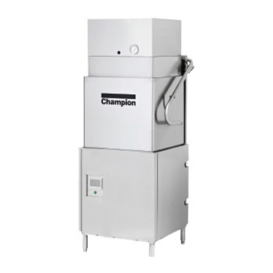
DH6000T-VHR
LISTED
3765 Champion Boulevard
Winston-Salem, NC 27105
(336) 661-1556 Fax: (336) 661-1660
Toll-free: 1 (800) 858-4477
Installation Manual
M2 SERIES
Models:
DH6000T-VHR
DH6000T
Tall hot water sanitizing machine w/fresh
water rinse and built-in stainless steel
electric booster, Optional Ventless Heat Recovery
DH6000-VHR
DH6000
Standard height hot water sanitizing machine w/
fresh water rinse and built-in stainless steel
electric booster, Optional Ventless Heat Recovery
2674 N. Service Road, Jordan Station
Ontario, Canada L0R 1S0
(905) 562-4195 Fax: (905) 562-4618
Toll-free: 1( 800) 263-5798
Issue Date: 4.30.22
Manual P/N
117471 rev. -
For machines beginning with S/N D22042134 and above
Printed in the USA
Advertisement
Table of Contents

Related Manuals for Champion M2 Series


Summary of Contents for Champion M2 Series
- Page 1 Installation Manual M2 SERIES Models: DH6000T-VHR DH6000T Tall hot water sanitizing machine w/fresh water rinse and built-in stainless steel electric booster, Optional Ventless Heat Recovery DH6000-VHR DH6000 Standard height hot water sanitizing machine w/ fresh water rinse and built-in stainless steel...
- Page 2 NATIONAL SERVICE DEPARTMENT ATTENTION Toll-free: 1-800-858-4477 The machine data plate Tel: (336) 661-1556 is located right front corner Fax: (336) 661-1660 of the front panel. Email: service@championinudustries.com Canada Toll-free: 1-800-263-5798 Tel: (905) 562-4195 Fax: (905) 562-4618 Email: service@moyerdiebellimited.com CAUTION: Warewashing chemicals are supplied by others.
- Page 3 Three ways to REGISTER YOUR PRODUCT and ACTIVATE YOUR WARRANTY. 4:34 PM • Use your mobile device and connect to the website www.championindustries.com to register your product • Scan the QR code http://champDW.us located on the lower front panel of the machine. •...
- Page 4 PRODUCT REGISTRATION BY FAX COMPLETE THIS FORM AND FAX TO: (336) 661-1660 in the USA 1-(800) 204-0109 in Canada PRODUCT REGISTRATION CARD Model Serial # Date of Installation: Company Name: Address: (Street) State/Province Zip/Postal Code Telephone #: ( Contact: Installation Company: Address: Telephone #: Contact:...
- Page 5 Revision History Revision History Specifications are subject to change based on continual product improvement. Revision Revised Serial Number Revision Date Pages Effectivity Description 4.30.22 D22042134 Released first edition...
-
Page 6: Limited Warranty
(b) 90 days after installation, whichever occurs first. In the event that The Company elects to repair, the labor and work to be performed in connection with the warranty shall be done during regular working hours by a Champion authorized service technician. -
Page 7: Table Of Contents
Detergent Signal for Dispensing Signal by others ........11 Rinse aid Signal for Dispensing System by others ........12 Vent Fan Control Supplied by others ............13 Optional Champion Chemical Dispensers ............ 14 Supervisor Menus ..................16 Enter Supervisor Menu ................ 16 Enter Chemical Setup Menu .............. - Page 8 Table of Contents Table of Contents (continued) Supervisor Menus (continued) Sleep ..........................21 Fill Time Exceeded ......................22 On for Celsius ........................22 Water Refresh ........................22 Navigation Buttons ......................22 I/O - Inputs Outputs ......................23 Active Faults ........................23 Cycle Count ........................24 Manuals ..........................24 Revision ..........................25 Start Delime ........................26 Factory Setup ........................25 MAINT ..........................26...
- Page 9 Table of Contents This Page Intentionally Left Blank...
- Page 10 Installation INSTALLATION Installation Codes The installation of the dishwasher must comply with all local electrical, plumbing, health and safety codes or in the absence of local codes, installed in accordance with the applicable requirements in the National Electrical Code, NFPA 70, Canadian Electrical Code (CEC), Part 1, CSA C22.1;...
-
Page 11: Installation
Installation Receiving Inspect the outside of the shipping carton for signs of damage and report any damage immediately to a supervisor. Remove the carton, inspect the dishwasher, and check the inside of the machine for accessories and installation parts. Register your machine by fax or online as soon as possible. CAUTION: Be careful when lifting and moving the machine to avoid damage. -
Page 12: Dish Table Connections
Installation Dish Table Connections CAUTION: Do not attach the dish tables until the dishwasher is set in its permanent location. Dish table flange Drill holes, apply sealant, & fasten flange to wash tank Side panel Inner wall of wash tank 1/2”... -
Page 13: Corner Operation - Corner Splash Shield
Installation Corner Operation - Corner Splash Shield Machines are shipped from the factory for straight through operation. To convert to for corner operation: The control panel must be accessible from the front as shown in Fig. 4. Install the optional splash shield, if included with machine, see Fig. 5. Detailed instructions can be found in Appendix A at the rear of this manual. -
Page 14: Corner Operation - Track Conversion
Installation Corner Operation - Track Conversion Follow the steps below to convert the track assembly for corner operation: Pull the track assembly straight up out of the machine. Rotate the track 180° and reinstall. Remove the guide attached to the track assembly, save the hardware. Reposition the guide on the right-hand side of the track assembly and secure with the existing fasteners. -
Page 15: Vhr Cold Water Connection - Dh6000-Vhr, Dh6000T-Vhr
Installation VHR Cold Water Connection DH6000-VHR, DH6000T-VHR MINIMUM 3/4" NPT COLD WATER SUPPLY COLD WATER Minimum/Maximum Incoming Minimum Incoming Supply Minimum/Maximum Operating Temperature Flowing Pressure Flowing Pressure 55-75º/13-24ºC 46-50 PSI 16 PSI Hot Water Connection- DH6000, DH6000T Standard and VHR MINIMUM 3/4"... -
Page 16: Drain Connection
Installation Drain Connection DRAIN Gravity Drain 1" NPT Connections CAUTION: The dishwasher drain connection must comply with all local plumbing, health and safety codes. Damage caused by improper installation is not covered by the limited warranty Automatic Electric Drain Valve Maximum Flow Rate: 15.0 US GPM/14.0 IPM. -
Page 17: Optional Mechanical Drain Water Tempering Kit Valve Kit
Installation Optional Mechanical Drain Water Tempering Valve Kit A drain water tempering field installation kit P/N 1117084 is included with the machine. Mechanical Water Valve COLD Requires a minimum 1/2" NPT cold water supply line. WATER Uses building water supply pressure. Minimum/Maximum Incoming Minimum Incoming Supply Minimum/Maximum Operating... -
Page 18: Electrical Connections - Single And Three Phase
Installation Electrical Connection - Single and Three Phase WARNING: Disconnect main power off at the dishwasher and main circuit breaker There may be more than one before performing work on the circuit. power source connected to the machine. Remove the right and front panels. Route conduit to the mounting bracket located at the right rear corner of the machine (see Fig. -
Page 19: Single And Two Point Power Connection Conversion
Installation Single to Two Point Power Connection Conversion Machine wiring can be converted from a single to a two point input power connection by installing a field conversion kit, P/N 901168. New electrical connection data plates must be applied in front of the input terminal blocks. Refer to end of this manual for conversion instructions. -
Page 20: Convert Dh6000 208-240Vac Only From 3Ph To 1Ph Operation
Installation Convert DH6000 208-240VAC Only From 3PH to 1PH Operation 1 Phase 208-240/60/1 LINE IN NOTE: The installer must contact the factory to receive the jumper wire, jumper bars, and replacement data plate before making the conversion. Install Jumper Wire Disconnect all power to the machine. -
Page 21: Detergent Dispensing System By Others
Installation Detergent Dispensing System by others: Detergent INJECTION POINT • WASH TANK CAPACITY: 10 US GAL/8.3 IMP. GAL/38 L • TWO 7/8" DIAMETER HOLES ON RIGHT-SIDE OF TANK • TOP HOLE IS DETERGENT INJECTION • BOTTOM HOLE IS DETERGENT PROBE PROBE CAUTION: Warewashing chemicals are supplied by... -
Page 22: Rinse Aid Signal For Dispensing System By Others
Installation Rinse aid Signal for Dispensing System by others. Rinse-aid R /A Fig. 20 - Rinse aid injection point CAUTION: Warewashing chemicals are supplied by others. Always follow supplier's instructions for proper handling and use. • 120VAC FUSE BLOCK • 2.0 AMP MAX LOAD RINSE AID SIGNAL CONNECTION. -
Page 23: Vent Fan Control Supplied By Others
Installation Vent Fan Control Supplied by others. Ventilation (Vent Fan Control) The standard DH6000 and DH6000T are equipped with a fused signal connection for an external vent fan contactor (supplied by others). STOP: The 120VAC signal is limited to a 1.0 AMP maximum load. DO NOT CONNECT A VENT FAN MOTOR TO THE SIGNAL TERMINALS. -
Page 24: Optional Champion Chemical Dispensers
2. Chemicals are supplied by others. Follow the chemical manufacturer's instructions for the handling and use of the chemicals. DETERGENT 3. Refer to the Detergent Concentration Graphs below to set the Champion chemical dispensers. Fig. 23 - Champion dispenser pumps DETERGENT CONCENTRATION GRAPHS - Graph 1 UltraKlene... - Page 25 Blank Page This Page Intentionally Left Blank...
-
Page 26: Supervisor Menus
Supervisor Menus - Optional Champion Chemical Dispenser Set-up Optional Champion Chemical Dispenser Set-up (continued) Instructions for the Supervisor and Chemical Supplier DISHWASHER START-UP: 1. Check chemical containers are full; pick-up tubes installed. 2. Turn water supply on. 3. Turn power on. -
Page 27: Detergent Sensors
Supervisor Menus - Optional Champion Chemical Dispenser Set-up Optional Champion Chemical Dispenser Set-up (continued) Instructions for the Supervisor and Chemical Supplier Chemical Setup Menu: (continued Sensor Options: Chemical dispensing controlled according to option IN-LINE only, TANK only or both IN-LINE and TANK. -
Page 28: In-Line Sensor Only Detergent Cycle Times
Supervisor Menus - Optional Champion Chemical Dispenser Set-up SUPERVISOR MENUS (continued) Optional Champion Chemical Dispenser Set-up (continued) Instructions for the Supervisor and Chemical Supplier IN-LINE SENSOR ONLY DETERGENT CYCLE TIMES (continued IN-LINE Sensor Operation Error (A): If the IN-LINE detergent sensor does not detect chemical within the 40 sec. prime cycle,... -
Page 29: In-Line And Tank Sensors Normal Operation
Supervisor Menus - Optional Champion Chemical Dispenser Set-up Optional Champion Chemical Dispenser Set-up (continued) Instructions for the Supervisor and Chemical Supplier IN-LINE and TANK Sensors Normal Operation: Detergent pump output = 3ml/sec. Machine fills. When the lower float is satisfied, detergent pump runs the fill set point for initial charge. -
Page 30: Supervisor Menus (Continued)
Supervisor Menus - Optional Champion Chemical Dispenser Set-up SUPERVISOR MENUS (continued) Optional Champion Chemical Dispenser Set-up (continued) Instructions for the Supervisor and Chemical Supplier SET DETERGENT CONCENTRATION - (See Fig. 39 a,b,and c for Sensor displays). The concentration display indicates the sensor that is ON. -
Page 31: Sleep
Supervisor Menus - Sleep, Delime Setup SLEEP NOTE: Access to the supervisor menu is active for five minutes. The 7777 password must be re-entered after 5 minutes. Press the SETTINGS button, "gears", (Fig. 42). The Supervisor Menu appears, (Fig. 43) Fig. -
Page 32: Fill Time Exceeded
Supervisor Menus - Fill Time Extended, Water Refresh, On for Celsius, On for French SUPERVISOR MENUS (continued) FILL TIME EXCEEDED: The time it must take to fill the wash tank is programmed with the Fill Time Extended button. If the programmed minutes are exceeded then the operation screen displays an alarm. -
Page 33: I/O - Inputs Outputs
I/O, Active Faults - Supervisor Menus SUPERVISOR MENUS I/O - Inputs/Outputs: • The I/O shows the operating state of components. • Machine operation can be checked using the I/O screen. Fig. 52 - Press SETTINGS on main screen. To access the I/O screen: Press the SETTINGS button on the main screen, (Fig. -
Page 34: Cycle Count
Supervisor Menus - Active Faults, Cycle Count, Manuals SUPERVISOR MENUS (continued) ACTIVE FAULTS: (continued) A green light indicates no fault, a red light indicates a fault is active, (Fig. 56). Active faults are displayed on the operator's main screen. See the Operation Manual for details. -
Page 35: Revision
Revision, Start Delime, Factory Setup - Supervisor Menus SUPERVISOR MENUS NOTE: Press the 'Back-up button (◄ ◄ ). REVISION: Press the REVISION button, (Fig. 59a) to display the program version number installed. The revision version is important for Fig. 59a - Revision troubleshooting and repair of the machine. -
Page 36: Maint
Supervisor Menus - MAINT (Maintenance) SUPERVISOR MENUS (continued) MAINT: CAUTION: Supervisors should consult an authorized service agent before making changes to MAINT menu settings. Fig. 62 - Main screen Press the SETTINGS button access supervisor menu, (Fig. 62). Press the MAINT button, (Fig. 63). The Enter Password screen appears. -
Page 37: Temp Setpoints
MAINT (Maintenance) - Supervisor Menus SUPERVISOR MENUS (continued) MAINT: (continued) TEMP SETPOINTS: Press the Temp Setpoints button, (Fig. 67a). A menu appears showing the factory default Temperature Setpoints for the wash tank = 168ºF/76.6ºC, and the Booster = 191ºF/83.3ºC. These Fig. -
Page 38: Fault Counters
DOOR LOCK: When ON, the door lock switch operates as required. DETERGENT: When ON, the Optional Champion detergent system is operational. DETERGENT LOCKOUT: When ON, the machine will not operate if detergent is not detected in the Champion detergent system. -
Page 39: Delime Setup
Delime Setup - Supervisor Menus SUPERVISOR MENUS (continued) DELIME SETUP: NOTE: Access to the supervisor menu is active for five minutes. The 7777 password must be re-entered after 5 minutes. Press the SETTINGS button on the main Fig. 73 - Main screen screen, (Fig. -
Page 40: Delime Notification Setup
Supervisor - Delime Notification Setup Supervisor Mode (MAINT): (continued) DELIME NOTIFICATION SETUP: DELIME SETUP activates and sets up the delime function. Press the DELIME button The DELIME SCHEDULE sets the number of hours of machine operation between delime. HOURS range = 100-10 hours. The factory default is 100. -
Page 41: Delime Operation
Delime Operation DELIME DELIME OPERATION: • Deliming removes mineral deposits from the machine with a deliming chemical. • The deliming process is automatic after the chemical is added to the machine. • Refer to Figs. 78 and 79 on the previous page. START DELIME: (continued) •... - Page 42 Delime Operation DELIME OPERATION: (continued) Close the doors. "FILLING" appears and machine fills, (Fig. 87). CAUTION: Follow the chemical supplier's use and handling instructions. Wear protective clothing, Fig. 87 - Machine fills and eye protection when handling chemicals. 10. "ADD DELIME CHEMICAL" appears. Open doors and add deliming chemicals in accordance with the chemical supplier's instructions.
- Page 43 Delime Operation DELIME OPERATION: (continued) 17. "FILLING" appears. Machine fills with fresh water, (Fig.92). 18. "DELIME RINSE IN PROGRESS" appears. Pump Fig. 92 - Fills with fresh water runs. Time remaining in this example counts down from the preset 5 minutes, (Fig. 93). 19.
-
Page 44: Fault Messages
Fault Messages FAULT MESSAGES: • Operation errors are displayed on the main screen with prompts to guide the operator through troubleshooting procedures and corrective actions. FILL TIME EXCEEDED: If the machine does not fill completely in the allotted time then "FILL TIME EXCEEDED" and a blinking fault icon appear, (Fig.99a and Fig. -
Page 45: Float Fault
Fault Messages ERROR MESSAGES: (continued) FLOAT FAULT: The floats are devices inside the machine that control filling and heating. If a float encounters a problem, then "FLOAT FAULT" and a blinking fault icon appear, (Fig. 101). Press the icon and an instruction screen appears. Follow the instructions and press RESET, (Fig. -
Page 46: Appendix A: Installing Dh6000T Corner Shield Kit, P/N 901114
APPENDIX A : Installing DH6000T Corner Splash Shield Kit P/N 901114 INSTALLING DH6000T CORNER SPLASH SHIELD KIT, P/N 901114 CAUTION: The machine will drain automatically when the dishwasher power is turned off. KIT PARTS: (1) SHIELD, CORNER SPLASH, P/N 337955, COMPOUND SEALING, P/N 104889, (2) SCREWS, 10-32 X 1/2"... - Page 47 APPENDIX A : Installing DH6000T Corner Splash Shield Kit P/N 901114 Remove the (4) bolts, locks, and washers securing the right-hand door guide cover. Save the fasteners and discard the cover, (Fig. 3). Guide Cover Fig. 3 Install the splash shield between the door guide and the front corner post (Fig. 4). The left side of the splash shield covers the door guide.
- Page 48 APPENDIX A : Installing DH6000T Corner Splash Shield Kit P/N 901114 Apply a small bead of sealing compound to the (4) fasteners saved in step 4. Secure the guide cover end of the splash shield to the machine, (Fig. 5). Sealing Compound Fig.
- Page 49 APPENDIX A: Installing DH6000T Corner Splash Shield Kit P/N 901114 Using the splash shield as a template, mark and drill two holes in the corner post. Secure the shield to the post using the 10-32 screws, nuts and washers provided in the kit. Fig.
-
Page 50: Appendix B: Kit P/N 901242, Dh6000/T 1 To 2-Point Terminal Block Conversion
Fig. 1 Check the contents of the kit, (Fig. 1). The new data plates must be included. Contact Champion National Service in USA @ 1-(800) 858-4477 or in Canada @ 1-(800) 263-5798 Disconnect power to the dishwasher and remove the front and right-side panels. - Page 51 APPENDIX B: 1-Point to 2-Point Electrical Connection Conversion, Kit P/N 901168 Kit P/N 901242, DH6000/T-M2 Series 1-Point to 2-Point Terminal Block Conversion ATTENTION CONTACT THE SERVICE DEPARTMENT FOR A 2-POINT CONNECTION DATA PLATE TO GO INTO THIS KIT BEFORE SHIPMENT.
-
Page 52: Appendix C: Manually Operating The Drain Valve
APPENDIX C: Manually Operating the Drain Valve Manually Operating the Drain Valve • To manually operate the new valve, four 2.5mm socket allen screws must be removed, the valve coil removed, and the valve globe rotated with pliers. • The valve coil has an indicator line showing valve position.
Need help?
Do you have a question about the M2 Series and is the answer not in the manual?
Questions and answers