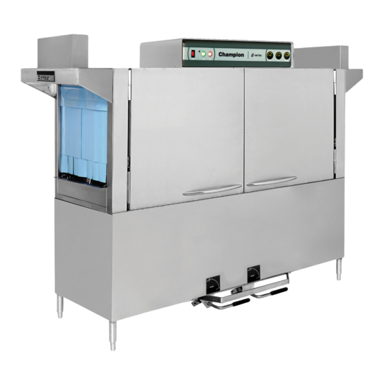
Champion 44 Installation And Operation Manual
E-series rack conveyor dishwasher
Hide thumbs
Also See for 44:
- Specifications (6 pages) ,
- Specifications (4 pages) ,
- Installation and service manual (134 pages)
Table of Contents
Advertisement
Installation/Operation with Service Replacement Parts
Beginning with Serial No. R3448 and above
Single Tank
Model 44
www.championindustries.com
3765 Champion Boulevard
Winston-Salem, NC 27105
336/661-1556 Fax: 336/661-1660
Toll-free: 800.858.4477
Single Tank w/Prewash
Model 66 PW
Two Tank w/Prewash
Model 64
2674 N. Service Road, Jordan Station
Ontario, Canada L0R 1S0
905/562-4195 Fax: 905/562-4618
Toll-free: 800.263.5798
E-series Rack Conveyor Dishwasher
Model Machines
Single Tank
44
66 PW
70 FFPW
80 HDPW
44 WS
66 WSPW
70 WSFFPW
80 WSHDPW
Single Dual-Rinse
44 DR
66 DRPW
70 DRFFPW
80 DRHDPW
44 DRWS
66 DRWSPW
70 DRWSFFPW
80 DRWSHDPW
54 DR
76 DRPW
80 DRFFPW
90 DRHDPW
Dishwasher serial no.
Issue Date: 11.16.10
Manual P/N 114315 rev. G
For machines beginning with S/N R3448 and above
Printed in USA
Dual Tank Rack
64
86 PW
90 PPPW
100 HDPW
120 HDPW
Chemical Sanitizing
44 LT
66 LTPW
70 LTHDW
80 LTHDPW
Advertisement
Chapters
Table of Contents

Related Manuals for Champion 44


Summary of Contents for Champion 44
- Page 1 Model Machines Single Tank Dual Tank Rack 66 PW 86 PW 70 FFPW 90 PPPW 80 HDPW 100 HDPW Single Tank 44 WS 120 HDPW Model 44 66 WSPW 70 WSFFPW 80 WSHDPW Single Dual-Rinse Chemical Sanitizing 44 DR 44 LT...
- Page 2 The USGBC and the CaGBC Member Logos are trademarks owned by the U.S. Green Building Council and The Canadian Green Building Council, respectively, and are used by permission. The logos signify only that Champion Industries and Moyer Diebel are a USGBC member and a CaGBC member respectively. USGBC and CaGBC do not review, certify nor endorse the products or services offered by its members.
- Page 3 USE CANADIAN WARRANTY CARD IN CANADA AND USA WARRANTY CARD IN THE UNITED STATES. PLACE STAMP HERE CHAMPION INDUSTRIES INC 3765 CHAMPION BLVD. WINSTON-SALEM, NC 27105...
- Page 4 WARRANTY REGISTRATION CARD Model Serial # Date of Installation: Company Name: Address: (Street) State or Province Zip Code Telephone #: ( Contact: Installation Company: Address: Telephone #: Contact: This Card Must Be Returned to Validate Machine Warranty: IMPORTANT IMPORTANT WARRANTY REGISTRATION CARD Model Serial # Date of Installation:...
- Page 5 Revision History Revision History A revision might be a part number change, new instructions, or information that was not available at print time. We reserve the right to make changes to this manual without notice and without in- curring any liability by making the changes. Dishwasher owners may request a revised manual, at no charge, by calling (800.858.4477) in the USA or (800.263.5798) in Canada.
-
Page 6: Limited Warranty
If a defect in workmanship or material is found to exist within the warranty period, Champion, at its election, will either repair or replace the defective machine or accept return of the machine for full credit; provided;... -
Page 7: Table Of Contents
Table of Contents E-series Rack Conveyor Dishwashers Revisions to this manual......................... Limited Warranty ........................... Model Descriptions ..........................Installation ....................Model Details ............1 Receiving ............2 Plumbing Connections......... 2 Drain Connections ..........4 Ventilation ............4 Electrical Connections ......... 5 Curtain Locations..........8 Hot Water Coil Tank Heat ........9 Door Safety Switches ..........11 Spray Arm and Scrap Screens ...... -
Page 8: Model Descriptions
Model Descriptions Model Descriptions Electric high temperature single tank and multiple tank rack conveyor dishwashers with built-in electric boosters in 40°F/22°C rise or optional 70°F/39°C rise. Steam high temperature single tank and multiple tank rack conveyor dishwasher with built-in steam booster in 40°F/22°C rise or an optional 70°F/39°C rise booster. Hot water coil dishwashers utilizing recirculating hot water through a wash tank heater coil to heat the wash water. -
Page 9: Installation
Single Tank with 26" Front Feed Prewash ....70 FFPW,80 FFPW, 70 WS FFPW • The 44 DR and 54 DR basic models are high temperature 180°F/80°C hot final rinse water sanitizing dishwashers. Prewash options are available in 22", 36", and 26"... -
Page 10: Receiving
Installation Receiving !!ATTENTION!! Use caution when moving or lifting the dishwasher to prevent damaging the dishwasher or the installation site. Check doorway and passageway clearance before moving the dishwasher. Remove dishwasher front panels and check under the machine base for obstructions before moving. 1. -
Page 11: Plumbing Connections
Installation Utilities Hot Water Connections NOTE: Only qualified personnel should make dishwasher plumbing connections. Connections must meet local plumbing and sanitary codes. Improper installation is not covered be the dishwasher warranty. Hot Water Requirements: 1. Connect a 3/4" NPT hot water supply line to the line strainer located at the top rear of the dishwasher. -
Page 12: Drain Connections
Installation Drain Connections 1. The 1-1/2" drain line was removed and packed inside the dishwasher prior to shipping. Install the drain line once the dishwasher has been placed in its final location. 2. Dual rinse (DR) models have a PVC drain line assembly packed inside the dishwasher also. Remove this assembly and install it at the unload end of the dishwasher. -
Page 13: Electrical Connections
6. Built-in electric booster heaters have a separate main power connection except Models 44 WS and 66WS. 7. Electric blower-dryers have a separate main power connection. 8. If the machine incoming voltage exceeds 208-240VAC then the Dual Rinse (DR) models have a step-down transformer mounted on the frame of the dishwasher to reduce the incoming voltage for the DR drain pump. - Page 14 Installation Electrical Connections (continued) Motor Rotation 1. Motor rotation was set at the factory. 2. The conveyor drive motor rotation is indicated by a red arrow located on the side of the motor. 3. Check if all motors are running in the wrong direction. Reverse the L1 and L2 wires on the output side of the dishwasher Main Terminal Block (MTB) located inside the top-mounted control cabinet.
- Page 15 Installation Chemical Connections 1. Use a qualified detergent/chemical supplier for detergent/chemical and dispensing equipment needs. 2. Labeled detergent control circuit connection terminals are provided in the control cabinet for detergent and rinse agent/sanitizer dispensing equipment (supplied by others). 3. The illustration on the right, shows the SIGNAL ONLY terminal board for the machine.
-
Page 16: Curtain Locations
Installation Curtain Locations 1. Refer to the illustrations below and hang the curtains as shown. J-hooks are located in the corners of each section to accept the curtain rods. • Standard long curtains 24” x 20-1/4” • High hood long curtains 24”... -
Page 17: Hot Water Coil Tank Heat
Installation Hot Water Coil Tank Heat Purging Air from the Dishwasher/Booster Heater System CAUTION: PERMANENT DAMAGE to the hot water recirculating pump can occur if the air is not purged from the dishwasher/booster heater system prior to placing the dishwasher into service. Follow the instructions carefully to prevent damage to the dishwasher hot water recirculating pump. - Page 18 Installation Hot Water Coil Tank Heat Purging Air from the Dishwasher/Booster Heater System (continued) Refer to the illustration on the previous page and follow the procedure below to purge the air from the system. Plumbing and electrical service connections must be completed before purging the system. To purge the air: Make sure the dishwasher main power switch is OFF.
-
Page 19: Door Safety Switches
Installation Door Safety Switches Dishwasher access doors are equipped with a door safety switch that automatically stops the dishwasher pumps and conveyor drive if a door is raised while the dishwasher is running. In addition, the dishwasher will not start if a door is left open. If the dishwasher is running and a door is raised, then lighted GREEN START pushbutton goes out and the pumps and conveyor drive stop. - Page 20 Installation Removing the Spray arm End Plugs Installing the Lower Spray arm Assembly...
- Page 21 Installation Installing the Lower Spray arm Assembly Removing the Spray arm End Plugs...
- Page 22 Installation Removing the Dual Rinse (DR) scrap screens...
- Page 23 Installation Removing the Dual Rinse (DR) scrap screens (continued)
-
Page 24: Check List
Initial Start-Up Check list 1. Remove white protective film from the dishwasher exterior. 2. Install lower panels to the dishwasher. 3. Remove any foreign material from inside of the machine. 4. Check dishwasher drain/overflows are closed and in securely seated. 5. -
Page 25: Operation
Check the wash tank temperature gauges located on the control cabinet. Minimum wash temperatures are: • 44 LT, 66 LT PW -140°F/60°C • 44, 54, 44 WS - 160°F/71°C to 175°F/79°C • 66 PW, 76 PW, 66 WS PW - 160-175°F/71-79°C •... -
Page 26: Cleaning And Maintenance
Cleaning Cleaning Cleaning your dishwasher is the best maintenance you can do. The cleaning intervals below are the minimum requirements for most dishwashers. You may need to clean your dishwasher more often when washing heavily soiled wares or during long hours of continuous operation. Daily or every 2 hours of operation 1. - Page 27 Cleaning Cleaning (continued) At the End of the Day Perform Steps 1-10 on the previous page. Remove the upper and lower rinse and wash spray arms and end plugs and flush with fresh water. Remove the Dual Rinse (DR) rinse arm assemblies and flush with fresh water. Clean the final rinse arm nozzles using a small paper clip.
- Page 28 Maintenance Maintenance Weekly 1. Inspect all water lines for leaks and tighten at joints if required. 2. Clean any detergent residue from the exterior of the machine. 3. Check that the drain/overflow pipes seat tightly in their drains. 4. Clean any accumulated scale from the heating element. 5.
- Page 29 Blank Page This Page Intentionally Left Blank...
-
Page 30: Digital Display
Digital Display E-Rack Digital Temperature Display Meters ATTENTION: The Digital Temperature Displays only indicate temperature, they do not control wash tank or final rinse booster heaters. Electro-mechanical thermostats continue to control the tank and final rinse heat circuits. 1. The analog temperature gauges have been replaced with digital temperature display meters. 2. - Page 31 Digital Display The set-point determines how the meter displays the yellow & green bar. For example, if the set-point is 70, then the bar displays yellow from 0-70 then green from 70 and above.
- Page 32 Digital Display Calibration: Calibration is an internal function of the display circuit board and does not calibrate temperature control of the dishwasher components. NOTE: The Thermister Plug and 1 wire from the Rinse Switch Connector must be disconnected from the display circuit board before calibration. To calibrate the display board: Turn dishwasher Power Switch OFF.
- Page 33 Digital Display Display Codes and Definitions The illustrations below show the codes that may appear in the temperature meter displays. 160 displayed and bar is blank...
-
Page 34: Troubleshooting
Troubleshooting Before calling for service check the following conditions. 1. Dishwasher main power and water supply is on. 2. Machine has been assembled correctly. 3. Conveyor is clear of any obstructions. 4. Drains are closed. 5. Screens and pump intake screens are clear. 6. -
Page 35: Service Replacement Parts
Prewash Track and Cradle Assembly ......................38 Single Tank Track and Cradle Assembly ...................... 40 Two Tank Track and Cradle Assembly ......................42 Prewash Screens ............................44 Single Tank Scrap Screens .......................... 46 Two Tank Scrap Screens ..........................48 Prewash Spray Arms ............................ 50 Single Tank Wash Spray Arms ........................ -
Page 36: Prewash Doors And Panels
Prewash Doors & Panels (L-R Direction Shown) - Page 37 Prewash Panels & Doors Item Part Description Qty. 328977 Panel Assy. Front Perimeter 22" PW Prewash 328978 Panel Assy. Front Perimeter 36" PW Prewash 329351 Panel, 25" End Standard 328030 Table Flange Support 329926 Baffle, Table Flange 328006 Support, 22" PW Rear Screen 113828 Rod Curtain 5/16 x 24-5/8"...
-
Page 38: Single Tank Doors And Panels
Single Tank Doors & Panels (L-R Direction Shown) - Page 39 Single Tank Doors & Panels Item Part Description Qty. 328974 Panel Assy., 44 Front Perimeter 330981 Panel Assy., 54 Front Perimeter 329351 Panel, 25” End Standard 329985 Bracket, Water Diverter 329926 Baffle 327857 Door, E 26" 108966 Door Handle 113691...
-
Page 40: Two Tank Doors And Panels
Two Tank Doors & Panels... - Page 41 Two Tank Doors & Panels Item Part Description Qty. 327857 Door, E26" 108966 Door Handle 100073 Screw 1/4-20 x 1/2 Truss Head 113691 Guide, U-channel Door 329351 Panel, 25” End standard 328975 Panel, 64 Front Perimeter 328976-01 Panel, 84 Front Perimeter Right Hand 328976 Panel, 84 Front Perimeter Left Hand 113720...
-
Page 42: Drive Motor Assembly
Drive Motor Assembly... - Page 43 0509199 Drive Motor Switch 327918 Bracket, Motor Switch Mounting See.Sheave.and.V-Belt.Chart.Below 327916 Plate, Drive Motor Mounting 327920 Plate, 44 Motor Assy Mounting 327917 Plate, 64 Motor Assy Mounting 327919 Bracket, Motor Spring Mounting 106482 Washer Lock 1/4 Split SST 102376 Washer, Flat 5/16 x 3/4 x .06 SST 113702 Spring 0.6OD x 0.095 Wire x 1.5 Lg...
-
Page 44: Conveyor Drive Assembly
Conveyor Drive Assembly Tank Bottom... - Page 45 103180 Wiper Ring 104916 Key 3/16 x 3/16 x 3/4 SST See.Sheave.and.V-belt.Chart.on.page.35. See.Sheave.and.V-belt.Chart.on.page.35. 327924 Bracket, 44 Drive Bearing Mounting 113860 Bearing, Sealed 5/8 Bore 104923 Screw 1/4-20 x 3/8 Round Head 100739 Bolt 5/16-18 x 3/4 Hex Head SST 106013...
-
Page 46: Prewash Track And Cradle Assembly
Prewash Track & Cradle Assembly Tank... - Page 47 Prewash Track & Cradle Assembly Item Part Description Qty. 113719 Switch, Door Safety 328045 Bracket, E PW IdlePump 113937 Magnet, SS 100764 Screw, 6-32 x 1/2 Round Head SST 108954 Nut, Grip 6-32 Hex Head W/Nylon Insert 106482 Washer Lock 1/4 Split 327833 Pin Idle Switch lever 100736...
-
Page 48: Single Tank Track And Cradle Assembly
SingleTank Track & Cradle Assembly (For DR, DRWS Models Only) (For WS and LT Models Only) - Page 49 100142 Nut, Grip 5/16-18 331988 Bracket Lower Washarm Support 206920 Rod, Support 100735 Bolt 1/4-20 x 5/8" Hex Hd., SST 414377 Cradle, E-44 Complete (Includes Items 10-13 and 16) 329486 Track, 26" Front Feed Assy. 900897 Kit. Idle Pump Assy.
-
Page 50: Two Tank Track And Cradle Assembly
Two Tank Track & Cradle Assembly... - Page 51 Two Tank Track & Cradle Assembly Item Part Description Qty. 113719 Switch, Reed Aleph 414344 Switch, Idle Assembly (Includes Items 3-8) 113937 Magnet, SS 100764 Screw, 6-32 x 1/2 Round Head SST 108954 Nut, Grip 6-32 Hex Head W/Nylon Insert 106482 Washer Lock 1/4 Split 327833...
-
Page 52: Prewash Screens
Prewash Screens... - Page 53 Prewash Screens Item Part Description Qty. 328958 Screen Assy 328959 Refuse Basket...
-
Page 54: Single Tank Scrap Screens
Single Tank Scrap Screens Tank Tank... - Page 55 Single Tank Scrap Screens Item Part Description Qty. 414328 Screen, E-44 L-R Front 414329 Screen, E-44 L-R Rear 414300 Basket, Rack 331922 Support, Screen 328653 Screen, Outboard, (E54DR)
-
Page 56: Two Tank Scrap Screens
Two Tank Scrap Screens... - Page 57 Two Tank Scrap Screens Item Part Description Qty. 414328 Screen, E-44 L-R Front 414329 Screen, E-44 L-R Rear 414300 Basket, Rack 331922 Support, Screen 328653 Screen, Outboard, (E-84 Only)
-
Page 58: Prewash Spray Arms
Prewash Spray Arms Rear Wall of Hood... - Page 59 Prewash Spray Arms Item Part Description Qty. 414569 Wash Manifold Assembly 6” Lower 113723 O-Ring,1.75 ID 113738 Block, Washarm Retaining 113540 Locknut 2NPT SST 113542 Gasket, Flat EDPM 2-3/8 ID 328028 Standpipe, 22” PW 414568 Wash Manifold Assy 6” Upper 328998 Bracket, Upper Safety 113555...
-
Page 60: Single Tank Wash Spray Arms
Single Tank Wash Spray Arms Rear Wall of Hood... - Page 61 Gasket, Flat EDPM 2-3/8 ID 113738 Block, Washarm Retaining 113723 O-ring 113540 Locknut 2NPT SST 327993 Standpipe, R-L 44 414317 Standpipe, L-R 44 414289 Wash Manifold Assy 14” Straight Upper (L-R) 414288 Wash Manifold Assy 14” Straight Upper (R-L) 113555...
-
Page 62: Two Tank Wash And Rinse Spray Arms
Two Tank Wash & Rinse Spray Arms Rear Wall of Hood Rear Wall of Hood... - Page 63 Two Tank Wash & Rinse Spray Arms Item Part Description Qty. 113542 Gasket, Flat EDPM 2-3/8 ID 113540 Locknut 2NPT SST 113738 Block, Washarm Retaining 113723 O-ring,1.75 ID 414289 Wash Manifold Assembly 14” Straight Upper (L-R) 414288 Wash Manifold Assembly 14” Straight Upper (R-L) 414291 Wash Manifold Assembly 10”...
-
Page 64: Float Switches
Float Switches Two Tank Single Tank Prewash... - Page 65 Float Switches Item Part Description Qty. 104584 Nut, Plain 1/2-13 107589 Washer, Flat 1/2” 111151 C-Clip 110854 Float Switch, Dual Prewash 113291 Float Switch, Dual Wash/Rinse E-44 113291 Float Switch, Dual Wash/Rinse E-64 110750 Gasket, Float Switch (Not Shown)
-
Page 66: Single Tank Electric Heat
Single Tank Electric Heat... - Page 67 Single Tank Electric Heat Item Part Description Qty. 113516 Heater 15/18KW 208V,380V 113517 Heater 15/16.3KW 230/240V, 400/415V 113518 Heater 15/16.3KW 460/480V 113519 Heater 15KW 575V 100153 Bolt, 3/18-16 x 1 Hex Head 104618 Washer 3/8 x 7/8 x 1/16 SST 108345 Gasket 3 x 3 x 1/8”...
-
Page 68: Two Tank Electric Heat
Two Tank Electric Heat Tank Rinse Wash... - Page 69 Two Tank Electric Heat Item Part Description Qty. 113516 Heater 15/18KW 200/220V (Wash) 113517 Heater 15/16.3KW 230/240V(Wash) 113518 Heater 15/16.3KW 460/480V (Wash) 113519 Heater 15KW 575V (Wash) 108345 Gasket 3 x 3 x 1/8” 2” Hole 113804 Heater 10/12.1 KW 200/220V (Rinse) 118842 Heater 10/11KW 230/240V (Rinse) 113883...
-
Page 70: Two Tank Steam Heat With K2 Booster
Two Tank Steam Heat with K2 Steam Booster... - Page 71 Two Tank Steam Heat with K2 Steam Booster Item Part Description Qty. 109069 Thermostat, Control 109887 Valve, 3/4" Solenoid 120VAC 109903 Kit, Repair Solenoid Valve 108516 Coil, Replacement 120VAC 105782 Union 1/2 NPT BI 104649 Relief, Valve 111380 Trap, Steam I/2" 100123 Cock, Gauge 1/4"...
-
Page 72: Single Tank Steam Heat
Single Tank Steam Heat Tank... - Page 73 Single Tank Steam Heat Item Part Description Qty. 327908 Coil, Steam RH (Shown) 327907 Coil, Steam LH 102554 Union 3/4 SST 100548 Locknut, 3/4NPT SST 113918 Nipple, Rtoe 3/4 x 1-3/4 100740 Bolt 5/16-18 x 1 Hex Head 102376 Washer 5/16 X 3/4 x 1/16 108345 Gasket 3 x 3 1/8”...
-
Page 74: Two Tank Steam Heat
Two Tank Steam Heat Tank Tank... - Page 75 Two Tank Steam Heat Item Part Description Qty. 327907 Coil, Steam LH 100740 Bolt 5/16-18 x 1 Hex Head 102376 Washer 5/16 X 3/4 x 1/16 108345 Gasket 3 x 3 1/8” 2IN Hole 106013 Washer Lock 5/16 Split 100154 Nut Plain 5/16-18 327908 Coil, Steam RH...
-
Page 76: Thermostats
Thermostats Two Tank Single Tank Front of Tank Wall... - Page 77 Thermostats Item Part Description Qty. 109069 Thermostat w/capillary - Single Tank 109069 Thermostat w/capillary -Two Tank 109069 Thermostat w/capillary -DR Models Only 110561 Thermostat, Fixed Hi Limit - Single Tank 110561 Thermostat, Fixed Hi Limit -Two Tank 201041 Washer 7/8 ID x 1/8 Thk - Single Tank 201041 Washer 7/8 ID x 1/8 Thk - Two Tank 109034...
-
Page 78: E-Series Thermostat And Junction Box
E-Series Thermostat and Junction Box Thermistor Connection Block Inter-wiring Connection Block Thermistor Assembly for Wash Tanks NOTE: Components and Quantities vary per Machine. - Page 79 E-series Thermostat and Junction Box Item Part Description Qty. 114521 End Cover, Single Terminal, D-MZB 114520 Terminal, Single MZB, 1.5 NS35 114519 End Block, E/NS 35 N 114518 End Cover, Double Terminal STTB 2.5, 114516 End Cover, Single Terminal D-ST 2.5 114515 Terminal, Single, Ground ST 2.5 (Green) 114517...
-
Page 80: Prewash Drain Overflow Assembly
Prewash Drain-overflow Assembly Tank Bottom... - Page 81 Prewash Drain-overflow Assembly Item Part Description Qty. 108875 Ring, Retaining 328824 Lever Drain Lift 206419 Rod, Overflow Lift 22"PW 106026 Washer 1/4 x 5/8 x 1/6 SST 328430 Overflow PW Mtd 111532 O-ring, Overflow 100735 Bolt 1/4-20 x 5/8 Hex Head 112257 O-ring, drain 111034...
-
Page 82: Single And Two Tank Drain Overflow Assembly
Single & Two Tank Drain-overflow Assembly Rinse 414897 Includes: 1 Jam Nut- 108521 O-ring - 111532 Rinse Overflow- 328993 Overflow Cover- 328984 Wash 414971 Includes: 1 Jam Nut- 108521 O-ring - 111532 Tank Bottom Wash Overflow- 328982 Oveflow Cover- 328984... - Page 83 Single & Two Tank Drain-overflow Assembly Item Part Description Qty. 113715 Ring, Retaining 328985 Lever Drain Lift 206442 Rod, Overflow Lift 206444 Block, drain lift 107966 Nut, Grip 10-32 w/Nylon Insert 112257 O-ring 100735 Bolt 1/4-20 x 5/8 Hex Head 106026 Washer 1/4 x 5/8 x 1/6 SST 111532...
-
Page 84: Final Rinse Piping With Booster
Final Rinse Piping with Booster From Booster Top of Hood Manifold Dimension in Chart is center to center of upper and lower spray pipe. - Page 85 Final Rinse Piping with Booster Item Part Description Qty. See Chart Below for Manifold P/N's 106026 Washer 1/4 x 5/8 x 1/16 SST 107967 Nut Grip 1/4-20 w/Nylon Insert See Chart Below for Upper Nozzle P/N's See Chart Below for Lower Nozzle P/N's 113795 Plug 11/16-16 Thread 113716...
-
Page 86: Fill Piping No Booster Or Steam Booster
Fill Piping No Booster or Steam Booster... - Page 87 Fill Piping No Booster or Steam Booster Item Part Description Qty. 101259 Plug, 1/8” NPT Brass 105976 Bushing, Red 3/4” NPT x 18” NPT Brass 100171 Bush Red Face 3/4” NPT x 1/2” NPT Brass 100599 Cross, 3/4”NPT Brass 100184 Nipple 3/4”...
-
Page 88: Fill Piping With Booster
Fill Piping with Booster... - Page 89 Fill Piping with Booster Item Part Description Qty. 100135 Gauge, Pressure 0-60 PSI 100171 Bushing, Red. Face 3/4" x 1/2" Brass 100184 Nipple, Close 3/4" NPT Brass 100206 Nipple, 1/2" NPT x 2-1/2" Lg. Brass 100209 Nipple, Close 1/2" NPT 100500 Breaker, Vacuum 1/2"...
-
Page 90: Cold Water Thermostat (Cwt) Piping
Cold Water Thermostat (CWT) Piping PREWASH TANK... - Page 91 Cold Water Thermostat (CWT) Piping Item Part Description Qty. 100209 Nipple, 1/2" NPT Close, Brass 100573 Locknut, 1/2" NPT Brass 100947 Nipple, 1/4" NPT Close Brass 101262 Nipple, 1/4" NPT x 1-1/2" Lg. Brass 102388 Bushing Reducing 1/2" NPT x 1/4" NPT Brass 102422 Elbow, 1/4"...
-
Page 92: Final Rinse Drain Assembly
Final Rinse Drain Assembly *Not a Part of Item 3 must order separately... - Page 93 Final Rinse Drain Assembly Item Part Description Qty. 100141 Nut, Grip 1/4-20 305218 Strainer, F/R Drain 107342 Drain basket assy. (Does not include Item 5) 112045 Washer,tailpiece (Comes with Item 3) 107473 Tailpiece...
-
Page 94: Prewash Pump Suction And Discharge
Prewash Pump Suction & Discharge Discharge Suction L-R Application Shown... - Page 95 Prewash Pump Suction & Discharge Item Part Description Qty. 109568 Gasket Pump Suction 307995 Flange, Suction 104203 Clamp, Hose M52 SST 113717 Hose, PW Suction 113731 Hose 22” PW Pump Discharge 104165 Clamp, Hose M40 SST 111964 Hose, Clamp Discharge 311761 Strainer, Pump Suction (Not Shown) 112379...
-
Page 96: Wash And Rinse Pump Suction/Discharge
Wash & Rinse Pump Suction/Discharge... - Page 97 Wash & Rinse Pump Suction/Discharge Item Part Description Qty. 110858 Hose Clamp Pump Discharge 113984 Hose Discharge Pump 111780 Hose Clamp Discharge 327997 Pump Motor Base 113538 Gasket Pump Suction 327906 Plate, Pump Suction 327904 Hood Pump Suction Pump.Base.Fasteners 100739 Bolt 5/16-18 x 3/4 Hex Head SST 102376 Washer 5/16 x 3/4 x 1/16...
-
Page 98: Pump Motor Assembly
Pump/Motor Assembly... - Page 99 Pump/Motor Assembly Item Part Description Qty. 100736 Screw 1/4-20 x 3/4 Hex Head 106482 Washer, Lock 1/4” 113705 Plug 1/2” NPT Countersunk Brass (2HP) (Wash/Rinse) 102504 Plug 1/2” NPT Brass Sq Head (1HP) (Prewash) 102500 Plug 1/4” NPT Brass 111943 Gasket .032 Thk (3 Notches) 111942 Gasket .015 Thk (2 Notches)
-
Page 100: Electric Booster Assembly 40-60˚F Rise
Electric Booster Assembly - 40°F/60°F Rise Prior to S/N RE3932 The booster tank heater with the center hole for inserting the high-limit thermostat is no longer available. Use the fitting on the corner of the booster tank to install the high-limit thermostat. - Page 101 Heater 12KW (60°F Rise)(460-480/3PH) 112061 Heater 12KW 575V 3Ph (60°F Rise) 328254 Bracket, Front Booster 113706 Elbow Street 3/4 x 45 Brass (E-44) 108954 Nut Grip 6-32 w/Nylon Insert 328048 Clamp, Thermostat Booster Tank (Not shown, use with item 11) 111235 Heater, 5/6.6KW 208/240 (40°...
-
Page 102: Electric Booster Assembly 70˚F Rise
Electric Booster Assembly - 70°F Rise Prior to S/N RE3932 The booster tank heater with the center hole for inserting the high-limit thermostat is no longer available. Use the fitting on the corner of the booster tank to install the high-limit thermostat. - Page 103 112060 Heater 12KW (460-480/3PH) 112061 Heater 12KW 575V 3PH 328254 Bracket, Front Booster 113706 Elbow Street 3/4 x 45 Brass E-44 108954 Nut Grip 6-32 w/Nylon Insert 328048 Clamp, Thermostat Booster Tank (Not shown, use with item 11) 109458 Flange Heater Bloc/off Element.Fasteners.(Qty.per.Element)
-
Page 104: Standard Control Cabinet
Control Cabinet... - Page 105 Red Pushbutton (Includes (1) of Item 5) Includes.the.following: 111615 Red Push Button 111616 Contact Block NC w/holder 113684 Decal 44/54 Cabinet (Single Tank) 113710 Decal 40/60/64 Cabinet (Two Tank) 107440 Thermometer 8ft Flanged (Wash) (Single Tank) 107440 Thermometer 8ft Flanged (Rinse) (Two Tank)
- Page 106 Control Cabinet Item Part Description Qty. 111625 Starter, Mtr., 1/6HP Drive 200-220/208-240V/60/1, 1.0-1.6A 111624 Starter, Mtr., 1/6HP Drive 208-220, 230-240V/60/3, .63-1.0A 111623 Starter, Mtr., 1/6HP Drive 460-480V/60/3, .4-.63A 111622 Starter, Mtr., 1/6HP Drive 575V/60/3, .24-.4A 113161 Starter, Mtr., 1HP Prewash 200-220/208-240V/60/1, 9.0-14.0A 111628 Starter, Mtr., 1HP Prewash 200-220/208-240/60/3, 4.0-6.3A 111626...
- Page 107 Control Cabinet with Digital Display Parts Illustration is on Page 100 Item Part Description Qty. 111980 Power Switch, Ciircuit Breaker 702084 LED Assy. 0512213 Switch, Piezo 22mm 114436 Decal, 2-Tank with Prewash 114438 Decal 2-Tank 114439 Decal 3-Tank 114532 Decal, 2 Tank w/o Prewash R-L 114437 Decal 2 Tank w/o Prewash L-R 114532...
-
Page 108: Control Cabinet With Digital Display
Control Cabinet with Digital Display... - Page 109 Control Cabinet with Digital Display Continued from Page 99 Item Part Description Qty. 111630 Starter, Mtr., 2HP Wash 200-220/208-240V/60/1, 13.0-18.0A 111629 Starter, Mtr., 2HP Wash 200-220/208-240V/60/3 6.0-10.0A 111627 Starter, Mtr., 2HP Wash 460-480V/60/3 2.5-4.0A 111627 Starter, Mtr., 2HP Wash 575V/60/3 2.5-4.0A 113161 Starter, Mtr., 3HP Was/Rinse 200-220/208-240V/60/3 9.0-14.0A 111628...
-
Page 110: Extended Vent Cowls
Extended Vent Cowls... - Page 111 Extended Vent Cowls Item Part Description Qty. 401487 Vent Stack Assembly (Includes Items 2-5) 201589 Regulator Assembly 112258 Nut Wing 1/4-20 SST 108954 Nut, Grip 6-32 w/Nylon Insert 104883 Screw 6-32 x 3/8” Round Head 328344 Vent Cowl Vent.Cowl.Fasteners.(Qty.per.Cowl) 100734 Bolt 1/4-20 x 1/2 Hex Head SST 106482 Nut Grip 1/4-20 SST...
-
Page 112: Standard Vent Cowls
Standard Vent Cowls... - Page 113 Standard Vent Cowls Item Part Description Qty. 401487 Vent Stack Assembly (Includes items 2-5) 201589 Regulator Assembly 112258 Nut, Wing 1/4-20 SST 108954 Nut, Grip 6-32 w/Nylon Insert 104883 Screw 6-32 x 3/8 Round Head 307228 Vent Hood 100734 Belt 1/4-20 x 1/2” Hex Head 100141 Nut Grip 1/4-20 401889-S...
-
Page 114: E44Dr Dual Rinse Assembly
E-44DR Dual Rinse Assembly See page 104 for pump breakdown... - Page 115 E-44DR Dual Rinse Assembly °°Item Part Description Qty. 329167 Manifold, E44DR Aux. Rinse 114291 O-ring 114290 Washer, rubber 107290 Nozzle 329009 tube, weld horizontal 329562 Screen RH 329281 Screen LH 331017 basket, screen 329465 Screen 111443 Switch, float 113986 Element 3.2/3.9KW 200-220V/60/1-3 113987 Element 3.2/3.9KW 220-240V/60/1-3 113988...
-
Page 116: E44Dr Recycle Pump Assembly
E-44DR Recycle Pump Assembly... - Page 117 E-44DR Recycle Pump Assembly Item Part Description Qty. 0502734 Stub Shaft 0502730 Seal Assembly (c/w spring) 0502729 Impeller 329281 Pump Housing 0501406 Screw, 8-32 x 1/2" 0501635 O-ring 0502732 Seal Screw, Housing 0502692 Pump Assembly, Complete (c/w motor and items 1-7) (Motor is not available as a separate service part)
-
Page 118: Single Tank Hot Water Coil Heat
Single Tank Hot Water Coil Heat... - Page 119 Single Tank Hot Water Coil Heat Item Part Description Qty. 100118 Union Elbow, 3/4" NPT Male Brass 100123 Petcock 1/4" Female Brass 100184 Nipple, 3/4" NPT x Close Brass 102396 Bushing Reducing, 1" NPT x 3/4" NPT Brass 102396 Elbow 3/4" NPT x 90° Brass 102444 E;bp 34"NPT x 90°...
-
Page 120: Double Tank Hot Water Coil Heat
Double Tank Hot Water Coil Heat... - Page 121 Double Tank Hot Water Coil Heat Item Part Description Qty. 100118 Union Elbow, 3/4" NPT Male Brass 100123 Petcock 1/4" NPT Closs Brass 100184 Bushing , Reducing 1-1/2" NPT x 3/4" NPT Brass 100595 Tee, 1-1/2" NPT x Close Brass 100596 Tee, 1-1/2"...
-
Page 122: 24" Sideloader
24" Sideloader... - Page 123 24" Sideloader Item Part Description Qty. 329927 Baffle, Sideloader 329352 Panel, End 312336 Bracket, Bar Support 312335 Pawl, Pin, Bar Support 109282 Spacer 108875 Pin, Cotter 3/32" x 1/2" 328955 Bracket Support, Sideloader 328941 24" L-R Sideloader 328942 24" R-L Sideloader 329317-1 24"...
-
Page 124: 30" Sideloader
30" Sideloader... - Page 125 30" Sideloader Item Part Description Qty. 329927 Baffle, Sideloader 329352 Panel, End 312336 Bracket, Bar Support 312335 Pawl, Pin, Bar Support 109282 Spacer 108875 Pin, Cotter 3/32" x 1/2" 328955 Bracket Support, Sideloader 328943 30" L-R Sideloader 328944 30" R-L Sideloader 329318-1 30"...
-
Page 126: Dishracks
Dish racks... - Page 127 Dish racks Item Part Description Qty. 101285 Rack Peg 101273 Rack Combination...
- Page 128 Blank Page This Page Intentionally Left Blank...
Need help?
Do you have a question about the 44 and is the answer not in the manual?
Questions and answers