Champion DH6000T-VHR Installation Manual
Hide thumbs
Also See for DH6000T-VHR:
- Operation, cleaning, and maintenance manual (28 pages) ,
- Installation manual (52 pages) ,
- Operation, cleaning, and maintenance manual (30 pages)
Table of Contents
Advertisement
Quick Links
- 1 Vhr Cold Water Connection-Dh6000-Vhr, Dh6000T-Vhr
- 2 Drain Connection
- 3 Electrical Connections - Single and Three Phase
- 4 Optional Champion Built-In Detergent and Rinse-Aid Dispensing System
- 5 Program the Chemical Dispensing System
- 6 Detergent Concentration Graphs
- 7 Detergent Probe/Signal for Chemical Dispensing Systems by Others
- Download this manual
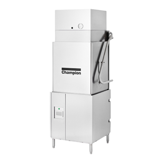
DH6000T-VHR
LISTED
3765 Champion Boulevard
Winston-Salem, NC 27105
(336) 661-1556 Fax: (336) 661-1660
Toll-free: 1 (800) 858-4477
Installation Guide
Models:
DH6000T-VHR
DH6000T
Tall hot water sanitizing machine w/fresh
water rinse and built-in stainless steel
electric booster, Optional Ventless Heat Recovery
DH6000-VHR
DH6000
Standard height hot water sanitizing machine w/
fresh water rinse and built-in stainless steel
electric booster, Optional Ventless Heat Recovery
2674 N. Service Road, Jordan Station
Ontario, Canada L0R 1S0
(905) 562-4195 Fax: (905) 562-4618
Toll-free: 1( 800) 263-5798
Issue Date: 5.11.20
Manual P/N
116042 rev. i
For machines beginning with S/N D190217104 and above
Printed in the USA
Advertisement
Table of Contents

Related Manuals for Champion DH6000T-VHR


Summary of Contents for Champion DH6000T-VHR
- Page 1 Issue Date: 5.11.20 Manual P/N LISTED 116042 rev. i For machines beginning with S/N D190217104 and above 3765 Champion Boulevard 2674 N. Service Road, Jordan Station Printed in the USA Winston-Salem, NC 27105 Ontario, Canada L0R 1S0 (336) 661-1556 Fax: (336) 661-1660...
- Page 2 NATIONAL SERVICE DEPARTMENT ATTENTION Toll-free: 1-800-858-4477 The machine data plate Tel: (336) 661-1556 is located right front corner Fax: (336) 661-1660 of the front panel. Email: service@championinudustries.com Canada Toll-free: 1-800-263-5798 Tel: (905) 562-4195 Fax: (905) 562-4618 Email: service@moyerdiebellimited.com COPYRIGHT © 2019 All rights reserved Printed in the USA...
- Page 3 Three ways to REGISTER YOUR PRODUCT and ACTIVATE YOUR WARRANTY. 4:34 PM • Use your mobile device and connect to the website www.championindustries.com to register your product. • Scan the UPC code http://champDW.us located on the front of the panel of the machine. •...
- Page 4 PRODUCT REGISTRATION BY FAX COMPLETE THIS FORM AND FAX TO: (336) 661-1660 in the USA 1-(800) 204-0109 in Canada PRODUCT REGISTRATION CARD Model Serial # Date of Installation: Company Name: Address: (Street) State/Province Zip/Postal Code Telephone #: ( Contact: Installation Company: Address: Telephone #: Contact:...
- Page 5 Revision History Revision History Specifications are subject to change based on continual product improvement. Revision Revised Serial Number Revision Date Pages Effectivity Description 4.29.19 D190217104 Released first edition 6.10.19 12-17 D190217104 Added chemical dispensing & delime set-up 8.5.19 iv-xi D190217104 Added specification sheets 9.16.19 9, 25...
-
Page 6: Limited Warranty
(b) 90 days after installation, whichever occurs first. In the event that The Company elects to repair, the labor and work to be performed in connection with the warranty shall be done during regular working hours by a Champion authorized service technician. -
Page 7: Table Of Contents
Electrical Connections - Single and Three Phase ..........8 Single and Two Point Power Connections ..........9 Converting 3-Phase to 1-Phase Operation ......... 10 Optional Champion Built-in Detergent and Rinse-aid Dispensing System .. 11 Program the Chemical Dispensing System ......... 12 Delime Programming ..................16 Detergent Concentration Graphs .............. -
Page 8: Specification Sheets
Built in detergent and rinse aid pumps SPECIFIER STATEMENT : Drain Water Tempering Kit (unmounted) Specified unit will be Champion model DH6000T with : Racks Ventless Heat-Recovery and Condensate Removal, high : Peg temperature, high-hood type dishwashing machine. - Page 9 Due to an ongoing value analysis program at 4-7/16" 6-1/4" 11-5/16" Voltage Amps Ampacity Protective Device 8-5/16" [112] [159] [288] Champion, specifications contained in this catalog [212] Wash 208-240/60/1 39-34 are subject to change without notice. 19-1/2" 4-11/16" Rinse 208-240/60/3 21-18 [496] [119] 4-7/16"...
- Page 10 : Door interlock – locks door closed during the vent SPECIFIER STATEMENT fan cycle : Single phase option Specified unit will be Champion model DH6000T high : Racks temperature, high-hood type dishwashing machine. : Peg Features, electronic controls, Rinse Sentry, Auto start,...
- Page 11 6-1/4" 11-5/16" Voltage Amps Ampacity Protective Device [159] 19-1/2" 8-5/16" Due to an ongoing value analysis program at Champion, Time cycles in seconds /16" [288] [496] [212] 208-240/60/1 39-34 specifications contained in this catalog are subject to 4-7/16" Wash [112] 19-1/2"...
- Page 12 : Drain Water Tempering Kit (unmounted) SPECIFIER STATEMENT : Racks : Peg Specified unit will be Champion model DH6000 with : Flat Ventless Heat-Recovery and Condensate Removal, high : Corner operation splash baffle temperature hood-type dishwashing machine. Features...
- Page 13 [91] [217] Time cycles in seconds Due to an ongoing value analysis program at Voltage Amps Ampacity Protective Device 6-1/4" 19-1/2" Champion, specifications contained in this catalog 4-11/16" 11-5/16" [159] Wash 208-240/60/1 39-34 [496] [119] [288] 4-7/16" are subject to change without notice.
- Page 14 : Door Interlock – locks door closed during the vent fan cycle SPECIFIER STATEMENT : Racks Specified unit will be Champion model DH-6000 high : Peg temperature hood-type dish-washing machine. Features : Flat HMI controls, Rinse Sentry, Auto start, up to 60 racks/hour, : Corner Operation splash baffle 0.73 US gals/rack [2.76 liters/rack, 0.61 imp.
- Page 15 Due to an ongoing value analysis program at 3-9/16" [853] Voltage Amps Ampacity Protective Device 19-1/2" 8-9/16" [91] Detergent Time cycles in seconds Champion, specifications contained in this catalog [496] [217] 208-240/60/1 39-34 Probe 4-7/16" are subject to change without notice. Wash [112] 6-1/4" 7/8" Dia 11-5/16"...
-
Page 16: Installation Codes And Safety Symbols
Installation Codes and Safety Symbols Installation Codes The installation of the dishwasher must comply with all local electrical, plumbing, health and safety codes or in the absence of local codes, installed in accordance with the applicable requirements in the National Electrical Code, NFPA 70, Canadian Electrical Code (CEC), Part 1, CSA C22.1;... -
Page 17: Receiving And Placement
Receiving and Placement - Installation Receiving Inspect the outside of the shipping carton for signs of damage and report any damage immediately to a supervisor. Remove the carton, inspect the dishwasher, and check the inside of the machine for accessories and installation parts. Register your machine by fax or online as soon as possible. -
Page 18: Dish Table Connections
Installation Dish Table Connections CAUTION: Do not attach the dish tables until the dishwasher is set in its permanent location. Dish table flange Drill holes, apply sealant, & fasten flange to wash tank Side panel Inner wall of wash tank 1/2”... -
Page 19: Corner Operation - Corner Splash Shield
Installation Corner Operation - Corner Splash Shield Machines are shipped from the factory for straight through operation. To convert to for corner operation: The control panel must be accessible from the front as shown in Fig. 4. Install the optional splash shield, if included with machine, see Fig. 5. Detailed instructions can be found in Appendix A at the rear of this manual. -
Page 20: Corner Operation - Track Conversion
Installation Corner Operation - Track Conversion Follow the steps below to convert the track assembly for corner operation: Pull the track assembly straight up out of the machine. Rotate the track 180° and reinstall. Remove the guide attached to the track assembly, save the hardware. Reposition the guide on the right-hand side of the track assembly and secure with the existing fasteners. -
Page 21: Vhr Cold Water Connection-Dh6000-Vhr, Dh6000T-Vhr
Installation VHR Cold Water Connection- DH6000-VHR, DH6000T-VHR COLD MINIMUM 3/4" NPT COLD WATER SUPPLY WATER MINIMUM/MAXIMUM MINIMUM/MAXIMUM INCOMING MINIMUM INCOMING OPERATING FLOWING PRESSURE TEMPERATURE SUPPLY FLOWING PRESSURE 55-75ºF / 13-24ºC 46-50 PSI 18-20 PSI WATER HARDNESS OF 3 GRAINS/US GAL - 0.83 IMP GAL - 5.3mg/L OR LESS. -
Page 22: Drain Connection
Installation Drain Connection DRAIN GRAVITY DRAIN, 1-1/2" NPT CONNECTION CAUTION: The dishwasher drain connection must comply with all local plumbing, health and safety codes. Damage caused by improper installation is not covered by the limited warranty AUTOMATIC ELECTRIC DRAIN VALVE MAXIMUM FLOW RATE: 15 US GPM/14 IMP. -
Page 23: Optional Drain Water Tempering Kit
Installation Optional Drain Water Tempering Kit The optional drain water tempering field installation kit P/N 1117084 is shipped with the machine unmounted. ELECTRIC WATER VALVE COLD WATER MINIMUM 1/2" NPT COLD WATER SUPPLY LINE USES BUILDING FLOWING PRESSURE MINIMUM/MAXIMUM INCOMING MINIMUM INCOMING MINIMUM/MAXIMUM OPERATING FLOWING PRESSURE... -
Page 24: Electrical Connections - Single And Three Phase
Installation Electrical Connection - Single and Three Phase WARNING: Electrocution may occur when working on energized circuits. Disconnect power at the main breaker or service disconnect switch, then lock out and tag it to indicate that work is being performed on the circuit. -
Page 25: Single And Two Point Power Connections
Installation Electrical Connection - Single and Three Phase WARNING: There may be more than one power source connected to the machine. Make sure all power sources are disconnected, locked and tagged out before working on the machine. 3 Phase Power Connection 1 Phase Power Connection 208-240/480V/60/3 208-240V/60/1... -
Page 26: Converting 3-Phase To 1-Phase Operation
Installation Converting 3 Phase to 1-Phase Operation 1 Phase 208-240/60/1 3 Phase to 1 Phase by installing of a Convert LINE IN jumper wire on the input power block and rewiring the wash tank and booster tank heaters. A jumper wire, jumper bars and a new data plate are stowed inside the control cabinet. -
Page 27: Optional Champion Built-In Detergent And Rinse-Aid Dispensing System
Installation OPTIONAL CHAMPION BUILT-IN DETERGENT DET R /A AND RINSE-AID DISPENSING SYSTEM (IF EQUIPPED) Detergent and rinse-aid dispensing pumps are located on left-side of machine (Fig.16). Pick-up tubing (Fig.17) exits left-side of machine to containers. The pick-up tubes are stowed on the back of the machine (Fig. 18). -
Page 28: Program The Chemical Dispensing System
Installation OPTIONAL CHAMPION BUILT-IN DETERGENT DET R /A AND RINSE-AID DISPENSING SYSTEM (IF EQUIPPED) Program the Chemical Dispensing System Use the digital touchscreen display to enter operating settings. Refer to the instructions below to set the system parameters. System Prep... - Page 29 Installation Cycle Times, Concentration, and Rinse Aid PW = 7777 LEGEND - Detergent/Rinse-aid Settings DE T ER GENT CYCLE TIMES Sets the run times for the detergent pump CONCENTRATION Sets detergent concentration in wash tank CYCLE TIMES DET PRIME RINSE AID Sets the rinse-aid pump run time CONCENTRATION DET PRIME...
-
Page 30: Detergent Concentration Graphs
Installation DETERGENT CONCENTRATION GRAPHS Based on manufacturer's recommended concentration. (Pink) Sodium Hydroxide 10-30% concentration Based on manufacturer's recommended concentration (Yellow) Potassium Carbonate 17% concentration Based on manufacturer's recommended concentration... - Page 31 Installation DET R /A Programming Rinse-aid Cycle - Sets the time the rinse-aid pump runs during final rinse. Factory Default = 5 sec. D E T ER G ENT Manual Priming (Password Free) CYCLE TIMES DET PRIME • The Detergent Prime (DET PRIME) and •...
-
Page 32: Delime Programming
Installation OPTIONAL CHAMPION BUILT-IN DETERGENT DET R /A AND RINSE-AID DISPENSING SYSTEM (IF EQUIPPED) Disabling the Optional Dispensing System and VHR The detergent/rinse aid dispensing system can be disabled if desired using the 'MAINT' programming function. The VHR system can be disabled on the same screen. To disable:... - Page 33 Installation DELIME Programming • The DELIME button accesses two functions: DELIME SET-UP and DELIME START. • Press 'DELIME SETUP' and enter password "7777" to access the settings. Factory Default Settings are: • DELIME = OFF • HOURS = 0 • Delime Wash = 20 •...
-
Page 34: Detergent Probe/Signal For Chemical Dispensing Systems By Others
Installation Detergent Probe and Injection Point for Chemical Dispensing System by others. WASH TANK CAPACITY: 10 US GAL/8.3 IMP. GAL/38 L TWO 7/8" DIAMETER HOLES AT LOWER RIGHT REAR CORNER OF TANK. - TOP HOLE IS DETERGENT INJECTION - BOTTOM HOLE IS DETERGENT PROBE. SIGNAL ENABLED DURING WASH CYCLE. -
Page 35: Rinse-Aid Injector/Signal For Chemical Dispensing Systems By Others
Installation Rinse-aid Injector for Chemical Dispensing System by others. STD. RINSE/RACK: .73 US GAL/.61 IMP. GAL/ 2.8L R /A POT,PAN,RINSE/RACK .73 US GAL/.61 IMP.GAL/ 2.8L 1/8" NPT PIPE PLUG AT THE REAR OF THE MACHINE NEAR THE VACUUM BREAKER FOR RINSE-AID INJECTION. SIGNAL ENABLED DURING FINAL RINSE CYCLE. -
Page 36: Shortening A Chemical Pick-Up Hose Supplied By Others
Installation Shortening a Chemical Pick-up Hose Supplied by Others 1. Remove the left-side panel to access the detergent and rinse-aid chemical pumps (Fig. 1). 2. The chemical tubes enter from the rear through grommets (Fig. 2). Fig. 1 Fig. 2 3. - Page 37 APPENDIX A : Installing DH6000T Corner Splash Shield Kit P/N 901114 INSTALLING DH6000T, CORNER SPLASH SHIELD KIT, P/N 901114 CAUTION: Turn off dishwasher power. The machine will drain automatically. KIT PARTS: (1) SHIELD, CORNER SPLASH, P/N 337955, COMPOUND SEALING, P/N 104889, (2) SCREWS, 10-32 X 1/2"...
-
Page 38: Ventilation (Vent Fan Control)
Installation Ventilation (Vent Fan Control) The standard DH6000 and DH6000T are equipped with a 120VAC, 1.5 A MAX signal for an external vent fan contactor (supplied by others). STOP: The 120VAC signal is designed only to operate an external vent fan contactor (supplied by others) and is limited to a 1.5A maximum load. - Page 39 Blank Page This Page Intentionally Left Blank...
-
Page 40: Appendix A: Dh6000T Corner Splash Shield Kit, P/N 901104
APPENDIX A : Installing DH6000T Corner Splash Shield Kit P/N 901114 Remove the (4) bolts, locks, and washers securing the right-hand door guide cover. Save the fasteners and discard the cover (Fig. 3). Guide Cover Fig. 3 Install the splash shield between the door guide and the front corner post (Fig. 4). The left side of the splash shield covers the door guide. - Page 41 APPENDIX A: Installing DH6000T Corner Splash Shield Kit P/N 901114 Apply a small bead of sealing compound to the (4) fasteners saved in step 4. Secure the guide cover end of the splash shield to the machine (Fig. 5). Sealing Compound Fig.
- Page 42 APPENDIX A: Installing DH6000T Corner Splash Shield Kit P/N 901114 Using the splash shield as a template, mark and drill two holes in the corner post. Secure the shield to the post using the 10-32 screws, nuts and washers provided in the kit. Fig.
-
Page 43: Appendix B: Kit P/N 901168, 1 To 2-Point Electrical Connection Conversion
APPENDIX B: 1-Point to 2-Point Electrical Connection Conversion, Kit P/N 901168 DH6000 Series 1-Point to 2-Point Electrical Connection Conversion Kit, P/N 901168 WARNING: Disconnect all power to the dishwasher before working on the machine. KIT PARTS: (1) P/N 111833, Input Terminal Block (1) P/N 336386, Bracket, Incoming Electrical (2) P/N 107136, Screw, 10-23 x 3/8"... - Page 44 APPENDIX B: 1-Point to 2-Point Electrical Connection Conversion, Kit P/N 901168 Position the Booster terminal block and make sure the booster wires disconnected in step 4 will reach to the block. (Fig. 4). MACHINE BOOSTER Fig. 4 The base should be predrilled for the bracket, however, if not, then use the bracket as a template and mark two holes...
- Page 45 APPENDIX B: 1-Point to 2-Point Electrical Connection Conversion, Kit P/N 901168 10. Connect the booster wires to 2-Point Machine Connection Data Plate Mod: DH6000T Series: VHR the booster terminal block (Fig.7). For supply connection, use copper connectors in accordance with local electrical code. Rated Minimum 90°C (194°F). Overcurrent Protection Device: Time Delay or Inverse Time Circuit Breaker Minium Supply Conductor Ampacity...
-
Page 46: Appendix C: Manually Operating The Drain Valve
APPENDIX C: Manual Valve Operation Manually Operating the Drain Valve • To manually operate the new valve, four 2.5mm socket allen screws must be removed, the valve coil removed, and the valve globe rotated with pliers. • The valve coil has an indicator line showing valve position.
Need help?
Do you have a question about the DH6000T-VHR and is the answer not in the manual?
Questions and answers