Champion DH-1000 Installation Manual
Door-type
Hide thumbs
Also See for DH-1000:
- Specifications (2 pages) ,
- Brochure & specs (7 pages) ,
- Installation manual (80 pages)
Table of Contents
Advertisement
Installation Manual with Service Replacement Parts
For Champion Models: DH-1000, DL-1000 • Moyer Diebel Models: MD1000HT, MD1000LT • Valu-Clean Models: VC1000, VC1000HT
High Temp
C
US
P.O. Box 4149
Winston-Salem, NC 27115
336/661-1556 Fax: 336/661-1660
Toll-free: 800.858.4477
Low Temp
2674 N. Service Road, Jordan Station
Ontario, Canada L0R 1S0
905/562-4195 Fax: 905/562-4618
Toll-free: 800.263.5798
Door-type
Dishwasher
Model: 1000 Series
High Temp
Hot water sanitizing machine w/ pumped
rinse and built-in stainless steel
electric booster
Low Temperature
Chemical sanitizing machine w/ pumped
rinse and 3 built-in chemical dispensing
pumps
Dishwasher serial no.
Issue Date: 4.23.08
Manual P/N 114313 rev. D
For machines beginning with S/N D07106631 and above
Printed in the USA
Advertisement
Table of Contents
Troubleshooting

Related Manuals for Champion DH-1000


Summary of Contents for Champion DH-1000
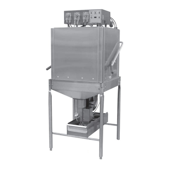
- Page 1 Installation Manual with Service Replacement Parts For Champion Models: DH-1000, DL-1000 • Moyer Diebel Models: MD1000HT, MD1000LT • Valu-Clean Models: VC1000, VC1000HT Door-type Dishwasher Model: 1000 Series High Temp Hot water sanitizing machine w/ pumped rinse and built-in stainless steel...
- Page 2 For future reference, record your dishwasher information in the box below. Model Number__________________________ Serial Number_______________________ Voltage________________Hertz_____________ Phase__________________ Service Agent __________________________________ Tel:______________________ Parts Distributor _________________________________ Tel:______________________ For all models: The data plate mounts to the right-side of the top-mounted control cabinet.
- Page 3 Complete the back of the POSTAGE PAID WARRANTY CARD below, then cut along the dashed lines and mail immediately to make sure that your machine warranty is validated. USE CANADIAN WARRANTY CARD IN CANADA AND USA WARRANTY CARD IN THE UNITED STATES.
-
Page 5: Revision History
The Revision History can contain part number changes, new instructions, or information that was not available at print time. • We reserve the right to make changes to these instructions without notice and without incurring any liability by making the changes.. •... - Page 6 C rise or an optional F/39 C rise booster. Low Temp Low temperature chemical sanitizing door-type dishwasher with built-in chemical dispensing pumps for detergent, rinse-aid, and sanitizer. The installation, and initial start-up of your dishwasher must be performed by qualified electricians, plumbers, and authorized service technicians who are trained in commercial dishwashers.
-
Page 7: Table Of Contents
1000 Series - Table of Contents ......................Revision History........................iv Limited Warranty High Temperature Door-Type Dishwasher Installation Guide ......................1 Unpack and Place ....................1 Electrical Connection .................... 5 Plumbing Connections ..................6 Chemical Dispensers ..................9 ... -
Page 8: Limited Warranty
Examples of the defects not covered by warranty include, but are not limited to: (1) Damage to the exterior or interior finish as a result of the above. (2) Use with utility service other than that designated on the rating plate. (3) Improper connection to utility service. -
Page 9: Installation Guide
Inspect the shipping pallet for splintered or broken boards. Inspect the exterior of the dishwasher while still mounted on the pallet for signs of damage. Contact the freight company immediately if damage is found and save all packing for inspection to verify your damage claim. - Page 10 Unpack and Place (1000 Series HT) 1. The installation of your dishwasher must be performed by qualified service personnel. 2. Problems due to improper installation are not covered by the Warranty. 3. The dishwasher data plate is located on the right-side of the top-mounted control cabinet cover. 4. Study the configuration diagrams below. They show the 2 ways that the dishwasher may be positioned.
- Page 11 1000 Series HT - Installation Guide Installation Guide Unpack and Place (1000 Series HT) 1. All dishwashers ship in the straight-through configuation. 2. Relocate the tracks and remove the wall-side door link components to convert the dishwasher for corner operation. Move Part 2 Move Part 1 Remove Interior Door Bracket...
- Page 12 Unpack and Place (1000 Series HT) 1. Compare the dishwasher and site utility connections. 2. Level the dishwasher by adjusting the bullet feet. 3. Raise the doors and check the door clearance to the ceiling. 4. Move the dishwasher to its permanent location. Note: Installers must follow applicable sanitation, safety, plumbing, and electrical codes and regulations;...
-
Page 13: Electrical Connection
3. Double-check that all power was disconnected from the dishwasher. 4. Locate the power cable knock out and main terminal block on the left-side of the cabinet. 5. Locate the Machine Electrical Connection Data Plate mounted near the terminal block. -
Page 14: Plumbing Connections
1. Locate the built-in stainless steel booster on the left-side of the dishwasher. Note: The existing hot water supply lines to the dishwasher must be 3/4" NPT or larger. To the best of your ability inspect, and verify that all supply piping meets the 3/4" NPT requirement. - Page 15 Blank page This page intentionally left blank...
- Page 16 1-7/8" stainless steel, slip-fit hose connection Max flow: 15 US gal/min. (13.5 Imperial gal/min) 57liters/min. Ventilation (1000 Series HT) 1. The factory has no requirements for vent hoods; but, local codes and regulations in your area supersede our suggestions. Consult your local building and health authorities for local requirements. 2. Dishroom ventilation must provide sufficient airflow to prevent excessive humidity in the work area. 200-400cfm/5.6- 11.3 k Liters/min - is sufficient.
-
Page 17: Chemical Dispensers
2. Do not connect a sanitizer chemical dispenser to the 1000 Series HT. 3. You may wish to contact a chemical supplier to supply the chemical dispensers and chemicals for liquid detergent and liquid rinse-aid. (Consult your local listings). - Page 18 Warning: Chemical dispensers must be electrically grounded in compliance with applicable electric codes. Warning: Disconnect the main electric supply and place a tag at the fuse or disconnect switch indicating that work is being performed on that circuit. Caution: Connecting chemical dispensers at points other than those recommended by the factory may damage the dishwasher electrical system.
- Page 19 Timer Cam microswitch (See diagrams above). Cam No.5 operates the detergent microswitch Cam No.7 operates the rinse-aid microswitch 8. Look to the right for the photo of a timer cam microswitch. Note the configuration of the switch, do you see how the common terminal is different than the Normally Closed (N.C.) and the...
- Page 20 Chemical Dispensers (1000 Series HT) Continued from page 11 10. There are 8 Cams on the cycle timer. They are numbered 1-8 starting at the timer motor side of the assembly. 11. Look at the underside of the detergent and the Rinse-aid timer microswitches and identify the common terminals.
- Page 21 Initial Start-up is completed Powering the dishwasher as described above, without knowing for certain that the Initial Start-up was performed, may make you liable for any damages stemming from your actions.
- Page 22 DOWN to prime the rinse- aid. Watch the chemical as it travels up the tube to the injection point sight-glass located on the right-hand side, top-rear corner of the machine. Release the switch when the chemical enters the sight- glass.
-
Page 23: Initial Start-Up
2. A manila card located above the power switch explains how to turn the machine on for the first time. See step No. 10 on the next page for the first DISHWASHER POWER UP procedure. Let's begin the Initial Start-up: 1. Check the placement of the dishwasher: Compare the machine location with the ... - Page 24 1000 Series HT - Installation Guide Installation Guide Initial Start-up (1000 Series HT) Continued from page 15 Check that the following utilities are connected to the dishwasher and ready for use: Electrical service Hot water supply ...
- Page 25 16. Release the fill switch. 17. Open the dishwasher door fully and check the water level inside the tank. The proper water level is just below the overflow tube and 3" [76 mm] from the lower sprayarm support. Measure from the back of the support up the tank toward the rear wall of the dishwasher. 3" [76mm]...
- Page 26 19. Check the green cycle light. It should illuminate throughout the 90-second cycle, then go out at the end of the cycle. When the doors are raised, the cycle light should again illuminate for 3-seconds and then go out. The 3-second light indicates the timer is resetting.
-
Page 27: Operation
2. Ensure internal circular tank screen, upper and lower spray arms and lower external scrap screen are clean and in place. 3. Close door. Turn POWER switch to the “ ON ” position. Lift “FILL/DRAIN” switch to the “FILL” position and hold for approximately 15-20 seconds, or until water flows from the wash tank into the lower scrap pan. - Page 28 The Rinse Sentry Feature The 1000 Series HT Rinse Sentry automatically monitors the final rinse water temperature in the built-in stainless steel electric booster heater. If the final rinse water in the booster falls below 180°F/82°C, the Rinse Sentry will extend the dishwasher's wash cyle time in order to give the booster heater additional time to provide the 180°F/82°C water temperature required.
-
Page 29: Cleaning And Maintenance
Do not scrub the interior with scouring pads, nor harsh detergents. Close the doors fully; the dishwasher will begin a normal cycle. At the end of the cycle, Push & hold the Fill/drain switch in the DRAIN position until the wash tank is empty Flip the dishwasher power switch to the OFF position Remove and clean circular wash tank screen. -
Page 30: Daily Maintenance
1. Inspect pump hoses, door linkage, springs, and exterior of dishwasher for wear. 2. Inspect the wash arm bearings and O-rings. 3. Check the condition of scrap screens,. and dishracks for bent or broken pieces. 4. Check the toggle switches and indicator lights for damage. -
Page 31: Troubleshooting
Clogged rinse nozzle and/or pipe ......Clean with paper clip/delime Improper water line size ... Have installer change to proper size 3/4" NPT... - Page 32 Clogged rinse nozzle and/or pipe ..........Clean with paper clip/delime Improper water line size ....Have installer change to proper size 3/4" NPT Low final rinse temperature Low incoming water ...... Check valve to be sure it is clean and operating. Defective thermometer ....Check for proper setting or replace Machine leaking Leaking at chemical hose .....
-
Page 33: Installation Guide
1000 Series - Installation Guide Model 1000 Series LT Installation Guide... -
Page 34: Unpack And Place
Unpack and Place (1000 Series LT) 1. The installation of your dishwasher must be performed by qualified service personnel. 2. Problems due to improper installation are not covered by the Warranty. 3. The dishwasher data plate is located on the right-side of the top-mounted control cabinet cover. 4. Study the configuration diagrams below. They show the 2 ways that the dishwasher may be positioned. - Page 35 1000 Series LT - Installation Guide Installation Guide Unpack and Place (1000 Series LT) 1. All dishwashers ship in the straight-through configuation. 2. Relocate the tracks and remove the wall-side door link components to convert the dishwasher for corner operation. Move Part 2 Move Part 1 Remove Interior Door Bracket...
- Page 36 Unpack and Place (1000 Series LT) 1. Compare the dishwasher and site utility connections. 2. Level the dishwasher by adjusting the bullet feet. 3. Raise the doors and check the door clearance to the ceiling. 4. Move the dishwasher to its permanent location. Note: Installers must follow applicable sanitation, safety, plumbing, and electrical codes and regulations;...
-
Page 37: Electrical Connection
Warning: Disconnect the main electric supply and place a tag at the fuse or disconnect switch indicating that work is being performed on that circuit. 1. Locate the control cabinet keys on the rear of the control cabinet. -
Page 38: Plumbing Connections
Note: Plumbing installer must connect a 3/4" NPT hot water supply line to the dishwasher. A 3/4" pressure regulating valve (PRV) (not supplied) must be installed in the water supply line and adjusted to 20 ± 5 psi/138 ± 35 kPa flow pressure. Installation of a 0-60 psi/0-414 kPa pressure gauge is recommended. - Page 39 Drain: 1-7/8" stainless steel, slip-fit hose connection Max flow: 15 Us gal/min. (13.5 Imperial gal/min) 57liters/min. Ventilation 1000 Series LT 1. The factory has no requirements for vent hoods; but, local codes and regulations in your area supersede our suggestions. Consult your local building and health authorities for local requirements. 2. Dishroom ventilation must provide sufficient airflow to prevent excessive humidity in the work area. 200-400cfm/5.6- 11.3 k Liters/min - is sufficient.
-
Page 40: Chemical Dispensers
Poor washing results may result if manual dosing is employed.. Note: Cartridge detergent systems are NOT RECOMMENDED for the 1000 Series LT dishwasher. Poor washing results may result if installed on this model. Note: The 1000 Series LT chemical dispensers are standard equipment. There are 3 built-in dispensers located on the front of the 1000 Series LT top-mounted control cabinet. Consult a local commercial dishwasher chemical supplier for the set-up and operation of the dispensing system. -
Page 41: Initial Start-Up
1000 Series LT - Installation Guide Installation Guide Initial Start-Up (1000 Series LT) Check that the following utilities are connected to the dishwasher and ready for use: Electrical service Hot water supply Drain Ventilation (if required by local regulations). - Page 42 Blank Page This Page Intentionally Left Blank...
- Page 43 Turn on the main power switch at the service disconnect switch. 3. Release the fill switch. 4. Open the dishwasher door fully and check the water level inside the tank. The proper water level is just below the overflow tube and 3" [76 mm] from the lower manifold measuring up the tank toward the rear of the dishwasher. 5. Operate the dishwasher for 10 cycles checking the temperature gauges to ensure the machine is maintaining the proper temperatures.
-
Page 44: Operation
Operation How to Operate your Dishwasher (1000 Series LT) 1. Make sure there is adequate supply of liquid detergent and rinse-aid, and sanitizer. Check the chemical containers and refill if necessary. 2. Ensure the overflow tube/drain ball are clean and in place, and the circular pump screen, upper and lower spray arms and lower external scrap screen are clean and in place. -
Page 45: Cleaning And Maintenance
Rinse the interior of the dishwasher with fresh water. Wipe the interior with a soft cloth. Do not scrub the interior with scouring pads, nor harsh detergents. Close the doors fully; the dishwasher will begin a normal cycle. At the end of the cycle, Push & hold the Fill/drain switch in the DRAIN position until the wash tank is empty Flip the dishwasher power switch to the OFF position Remove and clean circular wash tank screen. - Page 46 After all necessary preparations have been performed in accordance with the chemical supplier's instructions, the chemical supplier or qualified service agent may operate the delime switch to lock the dishwasher in a continuous wash mode. Refer to the photographs below: Flip the delime switch down to the wash position when the deliming is complete.
- Page 47 Call your authorized service agent or local service representative and schedule a complete inspection of your dishwasher by a trained professional. A Maintenance Tip - Schedule your annual maintenance when you can give the service agent unrestricted access to the dishwasher for at least 2 to 2-1/2 hours.
-
Page 48: Troubleshooting
Door safety switch faulty ....Contact your service agency Main switch off ......Check disconnect Low or no water Main water supply is turned off ..Turn on house water supply Drain/overflow tube is not in place and seated ...... Clean, replace and seat drain tube ............ - Page 49 Troubleshooting (continued) Condition Cause Solution Low final rinse temperature Low incoming water ...... Check valve to be sure it is clean and ............operating. Defective thermometer ....Check for proper setting or replace Machine leaking Leaking at chemical hose ..... Replace hoses Pump seal leaking ......Replace seal Leaking at pump hose ....
- Page 50 Blank Page This Page Intentionally Left Blank...
-
Page 51: Service Replacement Parts
1000 Series HT • Control cabinet enclosure ___________________________________ 1000 Series HT • Conrtol cabinet assembly ___________________________________ 1000 Series LT • Control cabinet enclosure with chemical dispensing pumps _________ 1000 Series LT • Control cabinet assembly ____________________________________ Top mounted assemblies _________________________________________________... - Page 52 Replacement Parts Item No. Part No. Description Qty. Unit ----------- motor pump 0512015 complete motor/pump assy , 115VAC/60/1 0512015-2 complete motor/pump assy , 220/60/1 0512015-3 complete motor/pump assy , 220/60/3 0512015-4 complete motor/pump assy , 220/50/3 114134 water slinger 114135...
- Page 53 Replacement Parts 1/4-20 locknut 1/4-20 locknut 1/4" washer 1/4" washer 1/4-20 x 3/4" 1/4 x 20 washer...
- Page 54 Item No. Part No. Description Qty. Unit 109985 booster element o-ring 111233 booster heater, 220V/60/1 & 3 9kW, 40°F rise 112059 booster heater, 220V/60/1 & 3 12kW, 70°F rise 107908 booster element cover 110768 3/4" brass line strainer 100184 3/4" brass close nipple 111437 3/4"...
- Page 55 Replacement Parts 6-32 x 1/4" screw 6-32 washer 10-32 nylon insert nut and washer...
- Page 56 S/N D5937 0510833-11 opt. cntrl. panel decal w/ prime switch/ prior to S/N D5937 0510824-1 control cabinet lock w/2 keys prior to S/N D07106631 DECALS Champion 114245 Champion HT Prime 114242...
- Page 57 Replacement Parts Hood...
- Page 58 105514 booster heat contactor 106402 fuse block 0503749 terminal board 900892 90-sec. timer conversion kit (Prior to S/N D6336) 417081 90-sec. timer assy SST (For S/N D6336 and above) 107351 power switch 0508551 green cycle light 0510399 fill/drain switch ---- 0510399...
- Page 59 Replacement Parts...
- Page 60 Item No. Part No. Description Qty. Unit 331081 control cabinet cover 0510872-1 sanitizer & rinse aid pump mtr. 115VAC, 14RPM 0510870-1 detergent pump motor, 115VAC, 108 RPM 114203 pump head assy. 108412 tube clamp SMP-2 107928 clear sanitizer feed tubing...
- Page 61 Replacement Parts Inner panel cut-out 1/4-20 x 1/4" truss-head screw Sanitizer = white Rinse Aid = blue Detergent = red Hood...
- Page 62 25 FLA 111036 relay socket 111068 120VAC relay 900892 90-sec. timer conversion kit (Prior to S/N D6336) 417081 90-sec. timer assy SST (For S/N D6336 and above) 0501373-1 delime switch 114192 cycle counter 0503749 terminal board 0501399...
- Page 63 Replacement Parts See page 52-53 for chemical dispenser pumps DETERGENT SANITIZER FILL RINSE AID DRAIN POWER CYCLE...
- Page 64 0510987 sight-glass 107930 blue rinse-aid feed tube feet 107929 red detergent feed tubing feet 107928 clear sanitizer feed tubing (1000 Series LT only) feet 113937 door safety magnet 113719 door safety switch 0312046-2 splash guard (1000 Series HT only) 0712046...
- Page 65 Replacement Parts Low Temp...
- Page 66 0512012 drain overflow tube 113489 retaining ring 202009 0510497 drain ball 0512049 sump screen 114236 thermometer w/ 8 ft. capillary (1000 Series HT) 0510845-1 2" stem thermometer (1000 Series LT) 0510846-1 reducing bushing 0312017 drain solenoid cover 0310771-3 drain lift rod 0510773-1...
- Page 67 Replacement Parts High Temp Thermometer Use Item 5 Low Temp Thermometer...
- Page 68 107962 handle grip 0301789-1 door lift bar 0510788-1 pivot bushing 0510787-1 white spacer 0310788-1 door handle pivot 114154 carriage bolt, 1/4-20 x 1/2" 0501421 hex head bolt, 1/4-20 x 1-3/8" 106026 flat washer, 1/4-20 100141 top-lock hex head nut, 1/4-20...
- Page 69 Replacement Parts...
- Page 70 Replacement Parts Item No. Part No. Description Qty. Unit 0312011 front panel clip 0312029-1 rear drain pan cover 0312029 front drain pan cover 331083 front panel (1000 Series HT only) 0310979 scrap basket...
- Page 71 Replacement Parts...
- Page 72 Replacement Parts Item No. Part No. Description Qty. Unit 0309472-4 front track 0309472-3 rear track 0309470-3 cross tube 0309472-6 cross track splash guard 0309472-5 track rail 101273 flat-bottom silverware rack A/R 101285 peg rack dishware A/R = as requested...
- Page 73 Replacement Parts...
- Page 74 Replacement Parts Item No. Part No. Description Qty. Unit 0510743-1 upper wash hub 0510495 thumbscrew 114153 sprayarm end plug (remove for cleaning) 0510774-2 spray pipe 0510849 spray pipe o-ring 114133 sprayarm bearing o-ring 0512063 thumbscrew bushing 0510741-1 lower wash hub...
- Page 75 Replacement Parts...
- Page 76 Blank Page This page intentionally left blank...
-
Page 77: Electrical Schematics
1000 Series HT & 1000 Series LT • Electrical schematics / Timer cycle charts Electrical Schematics and Timer Cycle Charts Models: 1000 Series HT • 1000 Series LT... - Page 78 Blank Page This page intentionally left blank...
-
Page 79: Electrical Schematics
Electrical schematics/Timer cycle chart • Low temperature model... - Page 80 Electrical schematics/Timer cycle chart • High temperature model...
Need help?
Do you have a question about the DH-1000 and is the answer not in the manual?
Questions and answers
sanitizer hose is starting to leak
To fix a leaking sanitizer hose for the Champion DH-1000, replace the hose.
This answer is automatically generated