Page 1
Model 64 Issue Date: 12.12.16 Manual P/N 115328 rev. D www.championindustries.com For machines beginning with S/N RE13077060 and above 3765 Champion Boulevard 2674 N. Service Road, Jordan Station Printed in USA Winston-Salem, NC 27105 Ontario, Canada L0R 1S0 (336) 661-1556 Fax: (336) 661-1660...
Page 2
For future reference, record your dishwasher information in the box below. Model Number__________________________ Serial Number_______________________ Voltage________________Hertz_____________ Phase__________________ Champion Service Agent __________________________________ Tel:______________________ Champion Parts Distributor _________________________________ Tel:______________________ National Service Department In Canada: In the USA: Toll-free: 1 (800) 263-5798 Toll-free:...
Page 3
REGISTER YOUR PRODUCT ONLINE Make sure you are connected to the internet then enter an address below: In the U.S.A. http://www.championindustries.com/register In Canada http://www.championindustries.com/canada/register...
Page 4
PRODUCT REGISTRATION BY FAX COMPLETE THIS FORM AND FAX TO: (336) 661-1660 in the USA 1 (800) 204-0109 in Canada PRODUCT REGISTRATION CARD Model Serial # Date of Installation: Company Name: Address: (Street) State Zip or Telephone #: ( or Province Postal Code Contact: Installation Company:...
Revision History Revision History A revision might be a part number change, new instructions, or information that was not available at print time. We reserve the right to make changes to this manual without notice and without incurring any liability by making the changes. Dishwasher owners may request a revised manual, at no charge, by calling 1 (800) 858-4477 in the USA or 1 (800) 263-5798 in Canada.
Champion's obligation with respect to labor associated with any repairs shall end (a) 120 days after shipment, or (b) 90 days after installation, whichever occurs first. In the event that Champion elects to repair, the labor and work to be performed in connection with the warranty shall be done during regular working hours by a Champion authorized service technician.
Table of Contents Table of Contents 
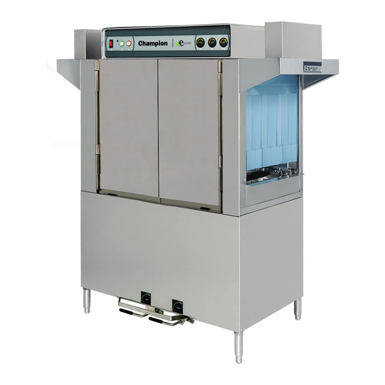
E-series Rack Conveyor Dishwashers Revision History ........................... i Limited Warranty ......................... ii Model Descriptions........................iv Installation ..................Installation Codes, Warranty Registration, Receiving ............1 Table Connections ....................... 2 Utilities, Hot and Cold Water Connections ..............3 Drain Connections, Steam Supply and Condensate Connections ........
Model Descriptions Model Descriptions Champion's single tank and two tank rack conveyor dishwashers are fully automatic. Standard equipment includes 1HP prewash, 2HP wash and 2HP power rinse pumps. The conveyor drive is a 1/6 HP motor. All models are available in right-to-left (R-L) or left-to-right (L-R) direction.
USA or http://www.championindustries.com/canada/register in Canada or by fax on the form provided at the front of this manual. If warranty registration is not returned to Champion within such period, the warranty will expire after one year from the date of shipment.
Page 10
Installation Table Connections The dishwasher and dish tables must be in their final locations and level before connection. The recommended table height is 34”/864mm. Slope the load end dish table away from the entrance of the dishwasher to prevent water from flowing into the dishwasher.
Installation Utilities Hot Water Connections NOTE: Only qualified personnel should make dishwasher plumbing connections. Connections must meet local plumbing and sanitary codes. Improper installation is not covered be the dishwasher warranty. Hot Water Requirements: 1. A water hardness of 3 grains/U.S. gal [51.3 mg/L] or less is recommended. 2.
Installation Drain Connections 1. The 1-1/2" drain line was removed and packed inside the dishwasher prior to shipping. Install the drain line once the dishwasher has been placed in its final location. 2. Connect the 1-1/2" NPT drain line above a drain sink or to a 1-1/2" or larger drain line connection. 3.
Installation Electrical Connections WARNING: Electrocution or serious injury may result when working on an energized circuit. Disconnect power at the main breaker or service disconnect switch before working on the circuit. Lock-out and tag the breaker to indicate that work is being performed on the circuit.
Page 14
Installation Electrical Connections (continued) Motor Rotation 1. Check the converyor drive motor to ensure it rotates in the correct direction. The motor shaft must rotate in a counterclockwise direction when viewed from the rear. 2. The dishwasher motors are phased together; therefore, if the conveyor motor rotation is correct then the pumo motors will also be correct.
Installation (Optional) Table Limit Switch A recommended option for any rack conveyor dishwasher is a table limit switch. The limit switch is installed at the end of the clean-end table and is designed to stop the conveyor and pumps in the event that dish racks back up on the clean-end table.
Installation Chemical Connections 1. Use a qualified detergent/chemical supplier for detergent/chemical and dispensing equipment needs. 2. Labeled detergent control circuit connection terminals are provided in the control cabinet for detergent and rinse agent/sanitizer dispensing equipment (supplied by others). 3. The illustration on the right, shows the terminal board for the machine. 4.
Installation Vent Fan Signal Connection 1. A terminal block is provided inside the top-mounted control cabinet to provide a 120VAC, 1 AMP Max Load signal. NOTE: The Vent Fan Signal Connection supplies 120VAC to a control relay (supplied by others) when the dishwasher is ON and O VAC when the dishwasher is OFF.
Installation Curtain Locations 1. Refer to the illustrations below and hang the curtains as shown. J-hooks are located in the corners of each section to accept the curtain rods. • Standard long curtains 24” x 20-1/4” • High hood long curtains 24”...
Installation Hot Water Coil Tank Heat Purging Air from the Dishwasher/Booster Heater System CAUTION: PERMANENT DAMAGE to the hot water recirculating pump can occur if the air is not purged from the dishwasher/booster heater system prior to placing the dishwasher into service. Follow the instructions on pages 9-10 to prevent damage to the dishwasher hot water recirculating pump.
Page 20
Installation Hot Water Coil Tank Heat Purging Air from the Dishwasher/Booster Heater System (continued) Refer to the illustration on the previous page and follow the procedure below to purge the air from the system. Plumbing and electrical service connections must be completed before purging the system. To purge the air: 1.
Installation Door Safety Switches Dishwasher access doors are equipped with a door safety switch that automatically stops the dishwasher pumps and conveyor drive if a door is raised while the dishwasher is running. In addition, the dishwasher will not start if a door is left open. If the dishwasher is running and a door is raised, the lighted GREEN START pushbutton goes out and the pumps and conveyor drive stop.
Installation Removing the Spray Arm End Plugs Installing the Lower Spray Arm Assembly...
Page 23
Installation Installing the Upper Spray Arm Assembly Removing the Spray Arm End Plugs...
Page 24
Installation Removing the Dual Rinse (DR) scrap screens Refer to the illustrations on this and the next page to remove and install the Dual Rinse (DR) scrap screens and rinse arm.
Page 25
Installation Installing the Dual Rinse (DR) scrap screens...
Installation Check list 1. Remove white protective film from the dishwasher exterior. 2. Install lower panels to the dishwasher. 3. Remove any foreign material from inside of the machine. 4. Check that the chemical supplies (supplied by others) are full. 5.
Operation Operation 1. Check that the spray pipes, curtains, and scrap screens are in place and clean. 2. Check that the overflow drains are closed. 3. Check the chemical supplies (supplied by others). Turn on the detergent dispenser switches. 4. Turn on the exhaust vent system (if applicable), and make sure it is operating. 5.
Operation Door Safety Switches Dishwasher access doors are equipped with a door safety switch that automatically stops the dishwasher pumps and conveyor drive if a door is opened while the dishwasher is running. In addition, the dishwasher will not start if a door is left open. If the dishwasher is running and a door is opened, the GREEN cycle light remains illuminated and the pumps and conveyor drive stop.
Page 29
Blank Page This Page Intentionally Left Blank...
Operation Scrap Screens 1. All models have scrap screens in the tanks. 2. Install two scrap screens in each wash tank making sure they fit securely without large gaps between them. 3. Install an internal refuse basket in each wash tank. 4.
Cleaning Cleaning Cleaning your dishwasher is the best maintenance you can perform. The cleaning intervals below are the minimum requirements for most dishwashers. You may need to clean your dishwasher more often when washing heavily soiled wares or during long hours of continuous operation. Daily or every 2 hours of operation 1.
Page 32
Cleaning Cleaning (continued) At the End of the Day 1. Perform Steps 1-10 on the previous page. 2. Remove the upper and lower rinse and wash spray arms and end plugs and flush with fresh water. 3. Remove the Dual Rinse (DR) rinse arm assemblies and flush with fresh water. 4.
Page 33
Maintenance Maintenance Weekly 1. Inspect all water lines for leaks and tighten at joints if required. 2. Clean any detergent residue from the exterior of the machine. 3. Check the drain operation. 4. Clean any accumulated scale from the heating element. 5.
Digital Display E-Rack Digital Temperature Display Meters ! ATTENTION ! The Digital Temperature Displays only indicate temperature, they do not control wash tank or final rinse booster heaters. Electromechanical thermostats continue to control the tank and final rinse heat circuits. 1.
Page 35
Digital Display Display Meter Operation Checks Check the Meter LEDs: 1. Turn the Dishwasher Power Switch ON. The 3-digit LEDs illuminate simultaneosly, the each LED bar illuminates from left-to-right. Check the Meter Temperature Set-point: Refer to the photo below and the "Rear view of the Digital Displat Circuit Board" on the next page. 1.
Page 36
Digital Display Calibration Calibration is an internal function of the display circuit board and does not calibrate temperayure control of th dishwaher components. NOTE: The Thermistor Plug and 1 wire from the Rinse Switch Connector must be disconnected from the display circuit board before calibration.
Page 37
Digital Display Display Codes and Definitions The illustrations below show the codes that may appear in the temperature meter displays.
Troubleshooting Troubleshooting Before calling for service, check the following conditions. 1. Dishwasher main power and water supply is on. 2. Machine has been assembled correctly. 3. Conveyor is clear of any obstructions. 4. Drains are closed. 5. Screens and pump intake screens are clear. 6.
Service Replacement Parts Illustration ......................Page Front View of Control Panel .................. Control Cabinet Interior View for Single Tank Models with Dual Rinse ......Control Cabinet Interior View for Two Tank Models ..........Prewash Panels and Curtains ................Single Tank Panels and Curtains ................Two Tank Panels and Curtains ................
Page 40
Service Replacement Parts (continued) Illustration ......................Page Single and Two Tank Electric Booster Assembly 40°F/70°F ........Single Tank Booster Heaters 40°F/70°F ..............Two Tank Booster Booster Heaters 40°F/70°F ............Two Tank and Heat Recovery Electric Booster Cabinet ..........Two Tank Steam Heat with K2 Steam Booster............Single Tank Steam Heat ..................
Front View of Control Cabinet (All Models) Models: E44DR, E54DR WASH FINAL RINSE L-R and R-L Machine Direction Shown Models: E66DRPW, E76DRPW, E70DRFFPW, E80DRFFPW, E80DRHDPW, E90DRHDPW PREWASH WASH FINAL RINSE L-R and R-L Machine Direction Shown Models: E64, E84 WASH RINSE FINAL RINSE L-R Machine Direction Shown...
Page 42
Control Cabinet Interior View for Single Tank Models with Dual Rinse- Layout 1 Note: Control Cabinet Cover P/N 334879 not shown. 3MOL 2MOL 1MOL This illustration shows a control cabinet with all options. Your control cabinet may not have the prewash components nor the additional parts required for the 22KW booster. Please disregard these extra components as necessary.
Control Cabinet Interior View for Single Tank Models with Dual Rinse Item Part Description Qty. COMMON ELECTRICAL PARTS (Not Voltage Specific) 114756 Circuit Board, Control 114759 Support, Circuit Board 115147 Block, Terminal 10-Pole 115345 Jumper, Slotted 115158 Label (TLS, Machine Run, etc.) 114898 Transformer, 120:24VAC 20VA 111827...
Page 44
Control Cabinet Interior View for Single Tank Models with Dual Rinse Item Part Description Qty. VOLTAGE SPECIFIC PARTS: 200-220V/60/3 111822 Fuse, Line 120VAC, 5A 600V LPCC-5 111624 Overload, Motor (Drive) 0.63-1.0A 111628 Overload, Motor (Prewash) 4.0-6.3A 111629 Overload, Motor (Wash) 6.0-10.0A 100922 Fuse, DR Heat 600V 20A, ATMR-20 107091...
Control Cabinet Interior View for Single Tank Models with Dual Rinse Item Part Description Qty. VOLTAGE SPECIFIC PARTS: 460-480V/60/3 111821 Fuse, Line 120VAC, 5A 600V LPCC-3 111624 Overload, Motor (Drive) 0.63-1.0A 111626 Overload, Motor (Prewash) 1.6-2.4A 111627 Overload, Motor (Wash) 2.5-4.0A 100913 Fuse, DR Heat 600V 10A, ATMR-10 107091...
Page 46
Control Cabinet Interior View for Two Tank Models Note: Control Cabinet Cover P/N 334879 not shown. RINSE WASH PREWASH DRIVE 4MOL 3MOL 2MOL 1MOL This illustration shows a control cabinet with all options. Your control cabinet may not have the prewash components nor the additional parts required for the 22KW booster. Please disregard these extra components as necessary.
Page 47
Control Cabinet Interior View for Two Tank Models Item Part Description Qty. COMMON ELECTRICAL PARTS (Not Voltage Specific) 114756 Circuit Board, Control 114759 Support, Circuit Board 115147 Block, Terminal 10-Pole 115345 Jumper, Slotted 115158 Label (TLS, Machine Run, etc.) 114898 Transformer, 120:24VAC 20VA 111827 Contactor, Heat 60 FLA...
Page 48
Control Cabinet Interior View for Two Tank Models Item Part Description Qty. VOLTAGE SPECIFIC PARTS: 200-220V/60/3 111624 Overload, Motor (Drive) 0.63-1.0A 111628 Overload, Motor (Prewash) 4.0-6.3A 111629 Overload, Motor (Wash) 6.0-10.0A 111629 Overload, Motor (Rinse) 109064 Transformer, 250VA 112482 Fuse, 600V LPCC-3.5A 230-240V/60/3 (Wash Tank Heat) 180171 Block, Fuse 600V 60A 3P J Type...
Page 49
Control Cabinet Interior View for Two Tank Models Item Part Description Qty. VOLTAGE SPECIFIC PARTS: 460-480V/60/3 111623 Overload, Motor (Drive) 0.4-.063A 111626 Overload, Motor (Prewash) 1.6-2.4A 111627 Overload, Motor (Wash) 2.5-4.0A 111627 Overload, Motor (Rinse) 2.5-4.0A 109064 Transformer, 250VA 112484 Fuse, 600V LPCC-1.5A 575V/60/3 (Wash Tank Heat) 111135...
Page 50
Solid State Control Board Cable Assemblies Run Light Final Rinse Wash Fill Prewash Fill Rinse Aid Solid State Circuit Bd. P/N 114756 Pumps Booster Heat Wash Heat DR/Rinse Heat Digital Display Rinse Reset DR Pump Item Part Description Qty. 115173 Harness, 6-pin Input E44/54 DR,DRPW, E64/84 E64/84PW 115174 Harness, 6-pin Output E44/54 DR,DRPW, E64/84 E64/84PW 1...
Page 51
Control Cabinet Interior View for Single Tank Models with Dual Rinse - Layout 2 Note: Control Cabinet Cover P/N 334879 not shown. This illustration shows a control cabinet with all options. Your control cabinet may not have the prewash components nor the additional parts required for the 22KW booster. Please disregard these extra components as necessary.
Page 57
Two Tank Panels and Curtains Item Part Description Qty. 113828 Rod, Curtain, 5/16 x 21-1/2" 113720 Curtain 24 x 20-1/4” 114012 Rod, Curtain, 5/16" x 23-1/2" 108043 Curtain, 24" x 13-1/4" 329926 Baffle 328030 Table Flange 329351 Panel, 25” End standard 100073 Screw 1/4-20 x 1/2 Truss Head 113944...
Page 59
Drive Motor Assembly Item Part Description Qty. 0509199 Drive Motor Switch 327918 Bracket, Motor Switch Mounting See Sheave and V-Belt Chart Below 327916 Plate, Drive Motor Mounting 327920 Plate, 44 Motor Assy Mounting 327917 Plate, 64 Motor Assy Mounting 327919 Bracket, Motor Spring Mounting 106482 Washer Lock 1/4 Split SST...
Junction Box Thermistor Connection Block Interwiring Connection Block NOTE: Components and quantities vary per machine.
Page 99
Junction Box Item Part Description Qty. 114521 End Cover, Single Terminal, D-MZB 114520 Terminal, Single MZB, 1.5 NS35 114519 End Block, E/NS 35 N 114518 End Cover, Double Terminal STTB 2.5, 114516 End Cover, Single Terminal D-ST 2.5 114515 Terminal, Single, Ground ST 2.5 (Green) 114517 Terminal , Double STTB 2.5 114512...
Final Rinse Piping (All Models) From Booster Top of Hood Manifold Dimension in Chart is center to center of upper and lower spray pipe.
Page 101
Final Rinse Piping (All Models) Item Part Description Qty. See Chart Below for Manifold P/N's 106026 Washer 1/4 x 5/8 x 1/16 SST 107967 Nut Grip 1/4-20 w/Nylon Insert See Chart Below for Upper Nozzle P/N's See Chart Below for Lower Nozzle P/N's 113795 Plug 11/16-16 Thread 109034...
Single and Two Tank Electric Booster Assembly - 40°F/70°F Rise ATTENTION: Install the highest Kw rated element in the top and the lowest rated element in the corner closest to Item 9 in the illustration above. Item 9 may be located on the opposite side of the booster.
Page 107
Single and Two Tank Electric Booster Assembly - 40°F/70°F Rise Item Part Description Qty. 1, 2, 3 Refer to the booster diagrams on the next four pages. 109985 Seal, Electric Heater Flange 110561 Thermostat w/Capillary, Fixed High Limit 240°F 108576 Cover, Booster No Cutout 328254 Bracket, Front Booster...
Page 145
Single Tank Hot Water Coil (HWC) Heat Item Part Description Qty. 100118 Union Elbow, 3/4" NPT Male Brass 100123 Petcock 1/4" Female Brass 100184 Nipple, 3/4" NPT x Close Brass 102442 Bushing Reducing, 1" NPT x 3/4" NPT Brass 102396 Elbow 3/4"...
Page 147
Two Tank Hot Water Coil (HWC) Heat Item Part Description Qty. 100118 Union Elbow, 3/4" NPT Male Brass 100123 Petcock 1/4" NPT Closs Brass 100184 Nipple, Close 3/4" NPT Brass 100595 Bushing, Reducer 1-1/2" x 3/4" Brass 100596 Tee, 1-1/2" NPT Brass 100613 Bushing Reducing, 1-1/2"NPT Brass 101000...
Electrical Schematios Electrical Schematics Illustration ................... Page Single Tank Electric/Steam ................... Single Tank Electric/Steam Hot Water Coil ............. Two Tank Electric/Steam ..................Two Tank Electric/Steam Hot Water Coil ..............12KW and 22KW Electric Booster ................ 15KW and 24KW Electric Booster ................ 30KW Heat Recovery Electric Booster ..............
Page 166
Circuit Board Diagnostics Input Section Output Section Run Light Final Rinse Wash Fill Prewash Fill Rack Control Module Rinse Aid (RCM) Pumps Booster Heat Wash Heat RCM Status/Jumpers DR/Rinse Heat Digital Display Rinse Reset DR Pump ! VERY IMPORTANT ! Improper jumper settings will cause erratic machine operation.
Page 167
Circuit Board Diagnostics Jumper Settings The photos at right show the four possible jumper settings for the control module operation. SINGLE TANK MACHINES W/DUAL RINSE (DR) Prewash Jumper Open DR Tank Jumper Closed Rinse Tank Open SINGLE TANK MACHINES W/DUAL RINSE (DR) and PREWASH Prewash Jumper Closed DR Tank Jumper Closed...
Page 168
Circuit Board Diagnostics The following pages illustrate the operational states of the circuit board during the operation of the various dishwasher models. This RUN LED Only Indicates that the has Power. Board All Models Current State: 1. Main Power is on. 2.