Lightware MX2-8X8-HDMI20-AUDIO User Manual
Hide thumbs
Also See for MX2-8X8-HDMI20-AUDIO:
- User manual (74 pages) ,
- Quick start manual (2 pages) ,
- User manual (72 pages)
Table of Contents
Advertisement
Quick Links
Advertisement
Table of Contents

Related Manuals for Lightware MX2-8X8-HDMI20-AUDIO


Summary of Contents for Lightware MX2-8X8-HDMI20-AUDIO
- Page 1 User’s Manual MX2-8X8-HDMI20-AUDIO...
-
Page 3: Safety Instructions
MX2-8x8-HDMI20 series User’s Manual SAFETY INSTRUCTIONS Class I Apparatus Construction. This equipment must be used with a mains power system with a protective earth connection. The third (earth) pin is a safety feature, do not bypass or disable it. The equipment should be operated only from the power source indicated on the product. - Page 4 3. All products to be returned to Lightware require a return material authorization number (RMA) prior to shipment and this number must be clearly marked on the box. If an RMA number is not obtained or is not clearly marked on the box, Lightware will refuse the shipment.
-
Page 5: Table Of Contents
IN WEB ............32 6.1. e ...... 32 StABLiShing the onneCtion 6.2. t ....32 Ayout of the uiLt 7. SOFTWARE CONTROL – USING LIGHTWARE DEVICE CONTROLLER ..34 7.1. i ........34 nStALL And pgrAde 7.2. d ......35 eViCe iSCoVery indow 7.3. - Page 6 Tips and tricks which you may have not known yet but can be useful. Printer icon Lightware Visual Engineering supports green technologies and eco-friend mentality. Thus, this document is made for digital usage primarily. If you need to print out few pages for any reason, we indicated some summary sheets with a printer-friendly icon which can be found at the left bottom corner of the actual page.
-
Page 7: Introduction
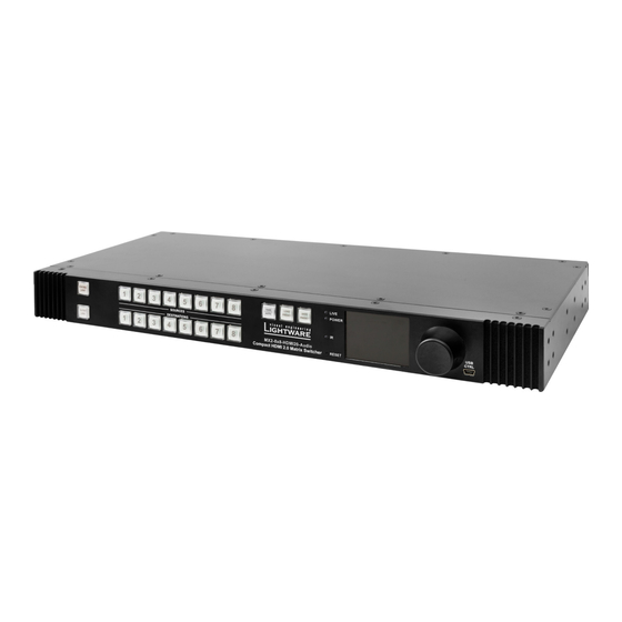
User’s Manual 1. Introduction Thank You for choosing Lightware Matrix Routers. The MX2-8x8-HDMI20-Audio is the first Lightware HDMI2.0 standalone matrix switcher that supports uncompromised 4K UHD resolution at 60Hz 4:4:4. Thanks to its compact size and silent design, it is particularly suitable for offices and meeting rooms, for 4K live events, and for futureproof operation centers. -
Page 8: Features
The two halves can then be recombined at the signal destination. Unique Front-to-Back Cooling Airflow Design MX2-8x8-HDMI20-Audio includes a groundbreaking new cooling design with front-to-back airflow. Inside the chassis, the airflow travels along guiding panes assuring that the most warm areas receive ample amount of cooling air volume. -
Page 9: Typical Applications
MX2-8x8-HDMI20 series User’s Manual 1.4. Typical Applications The following figures show different modes of the application: Analog audio HDMI Control active speakers 4K Control monitor MX2-8x8- HDMI HDMI20-Audio HDMI 4K projector HDMI 4K×2K@60Hz 4:4:4 Balanced analog audio 4K monitor 4K×2K@60Hz 4:4:4 Video Source 4Kx2K@60Hz 4:4:4 Audio amplifier... -
Page 10: Installation
2. Installation 2.1. Mounting Options The matrix can be mounted in several ways by the supplied two rack ears. Allen head screws fix them to the housing: WARNING! M4x8 size is the longest allowed screw for fixing the ears to the housing. A longer screw may touch internal parts. -
Page 11: Onnecting
MX2-8x8-HDMI20 series User’s Manual 2.2. Connecting Steps 4K PC Power outlet Media player HDMI HDMI Power Audio HDMI Audio amplifier 4K projector Ethernet Touch control Connect the desired sources to the HDMI input ports. Optionally connect an audio source to the Audio input port which is located next to the connected HDMI input port. -
Page 12: Audio Cable Wiring Guide
2.3. Audio Cable Wiring Guide Inputs and outputs of audio devices are usually symmetric or asymmetric. The main advantage of the symmetric lines is the better protection against the noise, therefore it is used widely in the professional audio industry. Symmetric audio is most often referred to as balanced audio, as opposed to asymmetric, which is referred to as unbalanced audio. - Page 13 MX2-8x8-HDMI20 series User’s Manual From Unbalanced Output to Balanced Input 2x6.3 (1/4") TS - Phoenix 2xRCA - Phoenix 3.5 (1/8") TRS - Phoenix From Balanced Output to Unbalanced Input Phoenix - 2x 6.3 (1/4") TS Phoenix - 2x RCA Phoenix - 3.5 (1/8") TRS - ATTENTION! Never join the phase-inverted (negative, cold or -) poles (both right and left) to the ground or to each other on the output side! It can damage the unit.
-
Page 14: Product Overview
Easy setting and menu navigation by the jog dial control. Keep Knob dial and click while getting feedback on the LCD. USB Control USB connector for local control functions (e.g. Lightware Device Controller software). Page 14 / 88 Chapter 3. Product Overview... -
Page 15: Rear View
MX2-8x8-HDMI20 series User’s Manual 3.2. Rear View AC Connector Standard IEC connector accepting 100-240 V, 50 or 60 Hz. Service Button Hidden button for special operations. RS-232 Port 3-pole Phoenix connector for RS-232 serial port. LAN Port RJ45 connector to control the matrix via LAN/Ethernet. Input Ports HDMI input ports for sources. -
Page 16: Lectrical C Onnections
3.3. Electrical Connections HDMI Input and Output Ports The matrix switchers are assembled with standard 19-pole HDMI connectors for inputs and outputs. The outputs are able to supply 500 mA current on DDC +5V output (pin 18) which is sufficient to supply power to certain devices (e.g. -
Page 17: Technologies
Common Problems Related to EDID Problem: My system consists of the following: a computer, a Lightware matrix, a WUXGA (1920x1200) LCD monitor, and an SXGA (1280x1024) projector. I would like to see the same image on the monitor and the projector. What EDID should I chose on the router?”... -
Page 18: Hdcp Management
OFF and ON again. 4.2. HDCP Management Lightware Visual Engineering is a legal HDCP adopter. Several functions have been developed which help to solve HDCP related problems. Complex AV systems often have both HDCP and non-HDCP components. The matrix allows transmitting HDCP encrypted and unencrypted signals. - Page 19 MX2-8x8-HDMI20 series User’s Manual 4.2.2. Disable Unnecessary Encryption HDCP-compliant Sink Encrypted signal Encrypted signal MX2-8x8-HDMI20 Matrix Protected HDCP-compliant content sink All the devices are HDCP-compliant, no manual setting is required, both protected and unprotected content is transmitted and displayed on the sink. Not HDCP-compliant Sink 1.
- Page 20 HDCP v2.2 Source and HDCP v1.4 Sink In this case the signal of an HDCP v2.2 compliant source is switched to an HDCP v1.4 compliant sink device. The signal is encrypted with HDCP v2.2 on the input and encrypted with HDCP v1.4 on the output of the matrix. A lower level of encryption may be applied only if the source device/content allows it - according to the HDCP standard.
-
Page 21: Pixel Accurate Reclocking
Without reclocking sparkles, noise, and jaggies can be seen on the image. Lightware’s sophisticated Pixel Accurate Reclocking technology fixes more problems than general TMDS reclocking. It removes not only intra-pair skew but inter-pair skew as well. -
Page 22: Operation
5. Operation 5.1. Powering on Connect the power cord to the AC input connector; the matrix is immediately powered on. After the self-test (about 30 seconds), the last configuration is loaded automatically. INFO The router has an internal emergency memory that stores all current settings and tie configurations. - Page 23 40) or sending LW3 protocol command (see section 9.7.4 on page 73). Using Lightware routers it is possible to lock a destination. This feature prevents an accidental switching to the locked destination in case of an important signal. OUTPUT LOCK Locking a destination means that no input selection or muting action can be executed on that particular destination.
- Page 24 Output Lock in Take Mode Step 1. Press and release the Output Lock button; it starts to CONTROL LOCK blink and all the buttons of any locked destinations DESTI light up (view state). OUTPUT LOCK Step 2. Press and release a destination button; it starts to CONTROL LOCK blink...
- Page 25 MX2-8x8-HDMI20 series User’s Manual Loading a Preset in Take Mode Step 1. Press and release the Load TAKE LOAD SAVE PRESET PRESET AUTO preset button. SOURCES DESTINATIONS Step 2. Press and release the TAKE LOAD SAVE PRESET PRESET AUTO desired source (memory SOURCES...
-
Page 26: O Perations
5.3. Front Panel LCD Menu Operations The company logo is displayed on the screen during the boot-up. The main menu is displayed after about 30 seconds later and the device is ready to use. Menu Structure The front panel has a color LCD that shows the most important settings and parameters structured in a menu. - Page 27 The lowest value of the brightness parameter is 1 when setting via the front panel. The setting is available in Lightware Device Controller software as well, but in that case, the lowest value is 0, which means the display is switched off; see section 7.7.4...
- Page 28 5.3.2. Input Ports Menu When entering the menu the available video input ports are listed. The icons display information about the port and the incoming signal (see below table). Select the desired input port and enter to see the submenu. Icon Icon is grey Icon is white...
- Page 29 MX2-8x8-HDMI20 series User’s Manual 5.3.3. Output Ports Menu When entering the menu the available video output ports are listed. The icons display information about the port and the outgoing signal (see below table). Select the desired output port and enter to see the submenu. Icon Icon is grey Icon is white...
- Page 30 Scrambling HDMI 2.0 standard introduced the Scrambling to the TMDS encoding which helps to decrease the energy peaks and hence the Electro Magnetic Interference (EMI). To maintain backward compatibility, HDMI 2.0 only requires the use of scrambling with data rates of above 3.4 Gbps per lane.
- Page 31 MX2-8x8-HDMI20 series User’s Manual Save Submenu The EDID of a connected sink can be saved to the User EDID memory as follows: Step 1. Navigate to the EDID/Save submenu. Step 2. Select the Name item and press the knob. Use the jog dial to select the desired EDID (D1-D8) and press the knob.
-
Page 32: Software Control - Using The Built-In Web
The built-in website of the matrix allows to connect and control the matrix via a web browser. The range of the controlling features are not so wide as in the case of Lightware Device Controller, but numerous information is displayed and many settings are available. - Page 33 MX2-8x8-HDMI20 series User’s Manual Built-in Webpage Displaying the Crosspoint Menu (Grid View) Built-in Webpage Displaying the Input Port Properties Window Chapter 6. Software Control - Using the Built-in Web Page 33 / 88...
-
Page 34: Software Control - Using Lightware Device Controller
7. Software Control – Using Lightware Device Controller The matrix can be controlled by a computer through the LAN or USB ports using Lightware Device Controller (LDC). The software can be installed on a Windows PC or Mac OS X. -
Page 35: Indow
The Ethernet tab consists of two lists: ▪ Favorite Devices: You can add any Lightware device that is connected via Ethernet and no need to browse all the available devices. Devices can be added by pressing the Add button or marking the desired device by the symbol in the All Devices list. -
Page 36: Evice Iscovery Indow Rosspoint Enu
Each number represents an output port. Click on the port to display the Port Properties window. Advanced View Displaying the Advanced view page, showing the Terminal window and the LW3 protocol tree. Page 36 / 88 Chapter 7. Software Control - Using Lightware Device Controller... - Page 37 Press the button to open the port settings window. Connected The ports with white background are currently connected to the Port(s) selected port. Press the button to open the port settings window. Chapter 7. Software Control - Using Lightware Device Controller Page 37 / 88...
- Page 38 Audio is not embedded Audio is embedded in the video stream in the video stream Port is unlocked Port is locked Port is unmuted Port is muted Page 38 / 88 Chapter 7. Software Control - Using Lightware Device Controller...
- Page 39 Step 4. Create the desired crosspoint settings by (de)selecting the ports; the changes are executed immediately. INFO Autotake mode remains active until it is switched off. Selecting another view mode or menu item does not change the Take/Autotake mode state. Chapter 7. Software Control - Using Lightware Device Controller Page 39 / 88...
-
Page 40: Port Properties
5-pole Phoenix input port. ▪ The 5-pole Phoenix audio connectors next to the HDMI output ports can provide de- embedded audio for amplifiers and audio systems. Page 40 / 88 Chapter 7. Software Control - Using Lightware Device Controller... - Page 41 2.2 and not allowed to convert and encrypt with HDCP v1.4. In this case the signal can be displayed only on a HDCP v2.2 compliant sink device. Chapter 7. Software Control - Using Lightware Device Controller Page 41 / 88...
- Page 42 The name of the last attached monitor's EDID is displayed (shown as Monitor Name display EDID in the EDID menu). HDCP capability Shows if the last attached display was HDCP-compliant. Page 42 / 88 Chapter 7. Software Control - Using Lightware Device Controller...
- Page 43 2.2 and not allowed to convert and encrypt with HDCP v1.4. In this case the signal can be displayed only on a HDCP v2.2 compliant sink device. Chapter 7. Software Control - Using Lightware Device Controller Page 43 / 88...
-
Page 44: Presets
16 characters. The followings are allowed when naming: letters (A-Z and a-z), hyphen (-), underscore (_), and numbers (0-9). Step 3. Press the Create New Preset button to store the configuration. Page 44 / 88 Chapter 7. Software Control - Using Lightware Device Controller... -
Page 45: Edid Menu
Opening Advanced Selecting none of the Edit EDID Editor with Select none memory places in the the selected EDID right panel Opening Easy Create EDID Creator Chapter 7. Software Control - Using Lightware Device Controller Page 45 / 88... - Page 46 Step 3. Browse the file in the opening window then press the Open button. Browsed EDID is imported into the selected User memory. ATTENTION! The imported EDID overwrites the selected memory place even if it is not empty. Page 46 / 88 Chapter 7. Software Control - Using Lightware Device Controller...
- Page 47 Step 3. Press the Clear selected button to delete the EDID(s). 7.6.3. EDID Summary Window Select an EDID from Source panel and press the Info button to display EDID summary. EDID Summary Window Chapter 7. Software Control - Using Lightware Device Controller Page 47 / 88...
- Page 48 Since above mentioned Advanced EDID Editor needs more complex knowledge about EDID, Lightware introduced a wizard-like interface for fast and easy EDID creation. With Easy EDID Creator it is possible to create custom EDIDs in four simple steps. By clicking on the Create button below the left panel, Easy EDID Creator is opened in a new window.
-
Page 49: Settings Menu
Connecting to the matrix via Ethernet and using LW2 port no. (default is 10001) the device accepts LW2 protocol commands. Using LW3 port no. (default is 6107) the device accepts LW3 protocol commands. Chapter 7. Software Control - Using Lightware Device Controller Page 49 / 88... - Page 50 The internal clock is supplied by a button cell when the device is switched off. If the set time is changed unintentionally or you met any weird behavior in connection with the internal clock, please contact support@lightware.eu. Page 50 / 88 Chapter 7. Software Control - Using Lightware Device Controller...
-
Page 51: Advanced View
The LDC can be set to warn the user before enable the Edit mode. Command Line Type the desired command and execute it by the Send button. Chapter 7. Software Control - Using Lightware Device Controller Page 51 / 88... -
Page 52: Lw2 Programmers' Reference
8. LW2 Programmers' Reference The device can be controlled through a reduced command set of LW2 protocol commands to ensure the compatibility with other Lightware products. The supported LW2 commands are described in this chapter. 8.1. LW2 Protocol Description The device accepts commands surrounded by curly brackets - { } - and responds data surrounded by round brackets - ( ) - only if a command was successfully executed. - Page 53 Description: Shows the hardware name and revision of the installed motherboard. Format Example Command {IS} → {is} Response (SL#●0●<MB_DESC>)CrLf ← (SL# 0 MX2-8X8-HDMI20-AUDIO (SL●END)CrLf V11_AAA0)CrLf ← (SL END) Explanation: The matrix reports its motherboard. 8.2.7. View Crosspoint Size Description: Shows the physical crosspoint size.
- Page 54 8.2.9. Query Control Protocol (RS-232) Description: The matrix can be controlled by different control protocols on the RS-232 port. This command queries the active protocol for the used control interface. ATTENTION! Be aware that different control interfaces can use different protocols. E.g. the Ethernet interface can use the LW3 protocol while the Serial interface uses P#2 protocol at the same time.
- Page 55 MX2-8x8-HDMI20 series User’s Manual 8.3.2. Batch Switch Outputs Description: The matrix is able to switch multiple outputs exactly at the same time. To do this, the normal switch commands have to be used. If the switch commands arrive at the router with less than 10 milliseconds delay, then the router collects the commands and changes the output connections together.
- Page 56 8.3.4. View Connections of all Outputs Description: Viewing all outputs’ connection showing the connected inout port. Legend 1: All <Ox> indexes show the corresponding output’s connection state. If value <O5> equals 04 it means that output 5 is connected to input 4. All <Ox> indexes are two digit ASCII characters (01, 02, 04, etc.).
- Page 57 MX2-8x8-HDMI20 series User’s Manual 8.3.6. Mute Specified Output Description: Mute output <out>. The output signal is turned off. Format Example Command {#<out>} → {#03} Response (1MT<out²>)CrLf ← (1MT03)CrLf Explanation: Output 3 is muted. No signal is present on output 3 now. INFO Muting does not change the crosspoint’s state but disables the output itself.
-
Page 58: S Ummary
8.4. Commands - Quick Summary Router Status Commands See in Operation Command section View Product Type 8.2.1 View Serial Number 8.2.2 View the Installed Firmware 8.2.3 View CPU Firmware Compile Time 8.2.4 {CT} View Firmware of the Controller 8.2.5 {FC} View Installed Motherboard 8.2.6 {IS}... -
Page 59: Lw3 Programmers' Reference
9. LW3 Programmers’ Reference 9.1. Overview The Lightware 3 protocol (LW3) is an ASCII-based, tree-structured protocol that provides outstanding flexibility. The protocol is easy to handle and programmatically still ease to parse, which is suitable for different products with a different feature list. - Page 60 Example: The following two ones are read-only properties: pr●/node1/node12.ReadOnlyProperty=value1 pr●/.DeviceName=MX2-8x8-HDMI20-Audio The following two ones are read-write properties: pw●/node1/node12.ReadWriteProperty=value2 pw●/.DeviceNickName=John Page 60 / 88...
- Page 61 MX2-8x8-HDMI20 series User’s Manual 9.1.1.3. Method The ‘method’ in the LW3 protocol is also a leaf. It cannot have a value, such as the properties, but it can be invoked with a parameter with the help of a special ‘CALL’ command. ▪...
-
Page 62: Lw3
9.1.3. Error Messages There are several error messages defined in the LW3 protocol, all of them have a unique error number. Format: XE●[primitive]●%EYYY:●[Error message] Legend: ‘X’ can be: ‘-’: syntax error. Cannot parse the command at all. ‘n’: node error. ‘p’: property error. -
Page 63: Commands
MX2-8x8-HDMI20 series User’s Manual 9.2. The Tree Structure The /SYS node is used for system-related settings such as front panel settings and health status parameters. /MANAGEMENT MANAGEMENT node contains network-related parameters, EDID date-time settings, and version numbers. The /EDID node contains all EDID-related settings MEDIA SETTINGS such as factory pre-programmed EDIDs and... - Page 64 Get all child nodes, properties and methods of a node Get all child nodes, properties and methods of a node with one command, without using a wild card. Command format: GETALL●[nodePath] Response format: (for nodes) n-●[nodePath] Response format: (for properties) pX●[nodePath].[propertyName]=[parameter] Legend: X can be:...
- Page 65 MX2-8x8-HDMI20 series User’s Manual Example: ˃ GET /EDID.* ˂ pr /EDID.EdidStatus=F49;F49;F49;F49;F49;F49;F49;F49; ˂ m- /EDID:copy ˂ m- /EDID:delete ˂ m- /EDID:reset ˂ m- /EDID:switch ˂ m- /EDID:switchAll 9.3.2. Set Command The setter command can be used to modify the value of a property. Command format: SET●[nodePath].[propertyName]=[newPropertyValue] Response format: The response for setting a property to a new value is the same as the response for the...
- Page 66 Legend: X can be: ‘O’: if the execution is successful. ‘F’: if the execution is failed, but the method could be executed. ‘E’: if the method could not be executed: e.g. illegal parameter count. Y can be: ▪ The return value of the method if any. ▪...
- Page 67 MX2-8x8-HDMI20 series User’s Manual 9.3.5. Signature For some command, the response can contain multiple lines. Each line is terminated with a carriage return (Cr, ‘\r’) and line feed (Lf, ‘\n’) characters. In several cases the number of the lines in the response cannot be determined in advance, e.g. the client is intended waiting for the whole response and also wants to be sure, that the received lines belong together and to the same command.
- Page 68 Subscribe to multiple nodes In order to subscribe to multiple nodes, the asterisk wild card can be used. Command format: OPEN●[nodePath]/* Response format: o-●[nodePath]/* Example: ˃ OPEN /MEDIA/XP/* ˂ o- /MEDIA/XP/* Get the active subscriptions for the current connection Command format: OPEN Response format: o-●[nodePath] Example: ˃...
-
Page 69: Efinitions
MX2-8x8-HDMI20 series User’s Manual A short example of how to use the subscription In the following, an example is presented, how the subscriptions are working and how to use them. In the example, there are two independent users controlling the device through two independent connections (‘Connection #1’... -
Page 70: Ystem Ommands
Command format: GET●/.ProductName Response format: pr●/.ProductName=<Product_name> Example: ˃ GET /.ProductName ˂ pr /.ProductName=MX2-8X8-HDMI20-AUDIO 9.5.2. Set the Device Label ATTENTION! The device label can be changed to a custom text which is displayed in many windows of the LDC. This writable parameter is not the same as the ProductName parameter. -
Page 71: S Ettings
MX2-8x8-HDMI20 series User’s Manual 9.5.6. Switch to Standby Mode The video transmission is disabled, the LCD is switched off, but remote connections (LAN, RS- 232) remain enabled in standby mode. See section 5.3.1 on page and the next section. Command format: CALL●/MANAGEMENT/POWER:standby() Response format: mO●/MANAGEMENT/POWER:standby= Example: ˃... -
Page 72: Ettings
9.6.4. Multiple Switching The whole crosspoint can be set by sending one command as follows. Command format: CALL●/MEDIA/XP/VIDEO:switchMulti(<O1_source>;<O2_source>;...; <O8_source>) Response format: mO●/MEDIA/XP/VIDEO:switchMulti=OK The source is not required to set on all output ports (see Example2). Example1: ˃ CALL /MEDIA/XP/VIDEO:switchMulti(I1;I2;I3;I4;I5;I6;I7;I8) ˂ mO /MEDIA/XP/VIDEO:switchMulti=OK Example2: ˃... - Page 73 MX2-8x8-HDMI20 series User’s Manual 9.7.2. Mute an Input Port Command format: CALL●/MEDIA/XP/VIDEO:muteSource(<In>;..;<Im>) Response format: mO●/MEDIA/XP/VIDEO:muteSource=OK Example: ˃ CALL /MEDIA/XP/VIDEO:muteSource(I1) ˂ mO /MEDIA/XP/VIDEO:muteSource=OK 9.7.3. Unmute an Input Port Command format: CALL●/MEDIA/XP/VIDEO:unmuteSource(<In>;..;<Im>) Response format: mO●/MEDIA/XP/VIDEO:unmuteSource=OK Example: ˃ CALL /MEDIA/XP/VIDEO:unmuteSource(I1;I3) ˂ mO /MEDIA/XP/VIDEO:unmuteSource=OK 9.7.4.
-
Page 74: Ettings Witching And C Roettingsettingspoint 9.7. V Ettings 9.8. P
9.8. Preset Handling The router can store presets and the followings are stored in each slot: input/output crosspoint state, muted/unmuted states. Preset loading has an effect on all ports, except the locked ones. 9.8.1. Create a New Preset Command format: CALL●/MEDIA/PRESET:create(<Preset_name>,VIDEO) Response format: mO●/MEDIA/PRESET:create= Legend: Up to 16 characters are allowed to name a Preset. - Page 75 MX2-8x8-HDMI20 series User’s Manual 9.9. Audio Input Port Settings INFO The current setting can be queried by using the GET command, see section 9.3.1. 9.9.1. Audio Mode Setting Command format: SET●/MEDIA/PORTS/VIDEO/<In>/ANALOGAUDIO.AudioMode= OFF|HDMI|ANALOG Response format: pw●/MEDIA/PORTS/VIDEO/<In>/ANALOGAUDIO.AudioMode= OFF|HDMI|ANALOG Example: ˃ SET /MEDIA/PORTS/VIDEO/I1/ANALOGAUDIO.AudioMode=ANALOG ˂...
-
Page 76: Ideo Utput Ort Ettings
9.10. Video Output Port Settings INFO The current setting can be queried by using the GET command, see section 9.3.1. 9.10.1. Signal Type (HDMI mode) Command format: SET●/MEDIA/PORTS/VIDEO/<On>/SETTINGS.ForcedSignalType= DVI|HDMI|AUTO Response format: pw●/MEDIA/PORTS/VIDEO/<On>/SETTINGS.ForcedSignalType= DVI|HDMI|AUTO Legend: ▪ DVI: The outgoing signal format is forced to be DVI. ▪... - Page 77 MX2-8x8-HDMI20 series User’s Manual 9.10.6. Conversion Mode ATTENTION! The signal conversion can be set on the input and output ports as well, but the desired signal is recommended to set on the output ports. The signal conversion on the input side is mainly for testing purposes.
-
Page 78: Udio Utput Ort Ettings
9.11. Audio Output Port Settings INFO The current setting can be queried by using the GET command, see section 9.3.1. 9.11.1. Audio Mode Setting Command format: SET●/MEDIA/PORTS/VIDEO/<On>/ANALOGAUDIO.AudioMode= OFF|HDMI|ANALOG|HDMI+ANALOG Response format: pw●/MEDIA/PORTS/VIDEO/<On>/ANALOGAUDIO.AudioMode= OFF|HDMI|ANALOG|HDMI+ANALOG Legend: ▪ Off: Audio is present neither in the HDMI stream nor on the Analog Audio output port. ▪... -
Page 79: Rs-232 P Ort Ettings
MX2-8x8-HDMI20 series User’s Manual Balance (Setting the Exact Value) Command format: SET●/MEDIA/PORTS/VIDEO/<On>/ANALOGAUDIO.Balance= <value> Response format: pw●/MEDIA/PORTS/VIDEO/<On>/ANALOGAUDIO.Balance= <value> Legend: The Balance value can be set between -100 and +100 (0=center). Example: ˃ SET /MEDIA/PORTS/VIDEO/O1/ANALOGAUDIO.Balance=10 ˂ pw /MEDIA/PORTS/VIDEO/O1/ANALOGAUDIO.Balance=10 Balance (Setting by Step Value) Command format: CALL●/MEDIA/PORTS/VIDEO/<On>/ ANALOGAUDIO:stepBalance(<step_value>) Response format: mO●/MEDIA/PORTS/VIDEO/<On>/... -
Page 80: Network Settings
9.13. Network Settings ATTENTION! When any parameter of the network settings is modified, always apply the new settings by using the following command: CALL /MANAGEMENT/NETWORK:applySettings() INFO The current setting can be queried by using the GET command, see section 9.3.1. 9.13.1. -
Page 81: Edid Management
MX2-8x8-HDMI20 series User’s Manual 9.14. EDID Management 9.14.1. Query the Emulated EDIDs Command format: GET●/EDID.EdidStatus Response format: pr●/EDID.EdidStatus=<E1_EDID>;<E2_EDID>;...;<E8_EDID> Legend: E1..E8: the emulated EDID on each input port. Example: ˃ GET /EDID.EdidStatus ˂ pr /EDID.EdidStatus=U1;U1;D2;D2;F49;F49;F49;F49 Explanation: The U1 (User memory) EDID is emulated on Input1 and Input 2. Dynamic (D2) EDID is emulated on Input3 and Input4, and F49 (Factory) EDID is emulated on the other input ports. -
Page 82: Ummary
9.15. LW3 Commands – Quick Summary System Commands Operation / Path Query the Product Name 9.5.1 /.ProductName Set the Device Label 9.5.2 /MANAGEMENT/UID/DeviceLabel=<Custom_name> Query the Serial Number 9.5.3 /.SerialNumber Resetting the Matrix 9.5.4 /SYS:softReset() Restore the Factory Default Settings 9.5.5 /SYS:factoryDefaults() Switch to Standby Mode 9.5.6... - Page 83 MX2-8x8-HDMI20 series User’s Manual Preset Handling Operation / Path Create a New Preset 9.8.1 /MEDIA/PRESET:create(<Preset_name>,VIDEO) Save the Settings to an Existing Preset 9.8.2 /MEDIA/PRESET/<Pres_name>:save(1) Load a Preset 9.8.3 /MEDIA/PRESET/<Pres_name>:load(1) Rename a Preset 9.8.4 /MEDIA/PRESET:rename(<Old_name>,<New_name>) Audio Input Port Settings Operation / Path Audio Mode Setting 9.9.1 /MEDIA/PORTS/VIDEO/<In>/ANALOGAUDIO.AudioMode=OFF|HDMI|ANALOG...
-
Page 84: Etwork Ettings
RS-232 Port Settings Operation / Path Protocol Setting 9.12.1 /MANAGEMENT/SERIAL.Protocol=LW2|LW3|P#2 Baud Rate Setting 9.12.2 /MANAGEMENT/SERIAL.Baudrate=<value> Network Settings Operation / Path Query the Current IP Address 9.13.1 /MANAGEMENT/NETWORK.IpAddress Set a Dynamic IP Address 9.13.2 /MANAGEMENT/NETWORK.DhcpEnabled Set a Static IP Address 9.13.3 /MANAGEMENT/NETWORK.StaticIpAddress EDID Management Operation / Path... -
Page 85: Appendix
MX2-8x8-HDMI20 series User’s Manual 10. Appendix 10.1. Specifications General Compliance ........................CE EMC compliance (emission) ................. EN 55032 EMC compliance (immunity) ................. EN 55024 RoHS compliance ......................Yes Warranty ........................3 years Cooling ............... by cooling fans, air flows from front to rear Operating temperature ..............0 to +55 °C (+32 to +122°F) Operating humidity .............. -
Page 86: Echanical Rawings
TAKE LOAD LOAD SAVE SAVE LOCK AUTO AUTO PRESET PRESET PRESET PRESET SOURCES DESTINATIONS OUTPUT CTRL MX2-8x8-HDMI20-Audio LOCK Compact HDMI 2.0 Matrix Switcher Rear view 100-240 VAC 50/60 Hz RS-232 SERVICE TX RX AUDIO AUDIO AUDIO AUDIO AUDIO AUDIO AUDIO AUDIO HDMI 2.0... -
Page 87: Actory Edid L Ist
MX2-8x8-HDMI20 series User’s Manual 10.3. Factory EDID List Mem. Resolution Type Mem. Resolution Type 640 x 480 @ 60.00 Hz Universal HDMI EDID; all audio, deep color 848 x 480 @ 60.00 Hz F50-F97 Reserved 800 x 600 @ 60.32 Hz 1280 x 720 @ 60.00 Hz HDMI... -
Page 88: Actory Efault Ettings
10.4. Factory Default Settings Parameter Setting / Value Network Settings IP address Dynamic (DHCP is enabled) RS-232 Port Port setting 57600 BAUD, 8, N, 1 Control protocol LW3 protocol Video Input/Output Ports Crosspoint setting Input 1 on all outputs Input port: enabled (v1.4) HDCP mode Output port: Auto Color space / color range...
Need help?
Do you have a question about the MX2-8X8-HDMI20-AUDIO and is the answer not in the manual?
Questions and answers