Table of Contents
Advertisement
Quick Links
INSTALLATION
&
OPERATION
M A N U A L
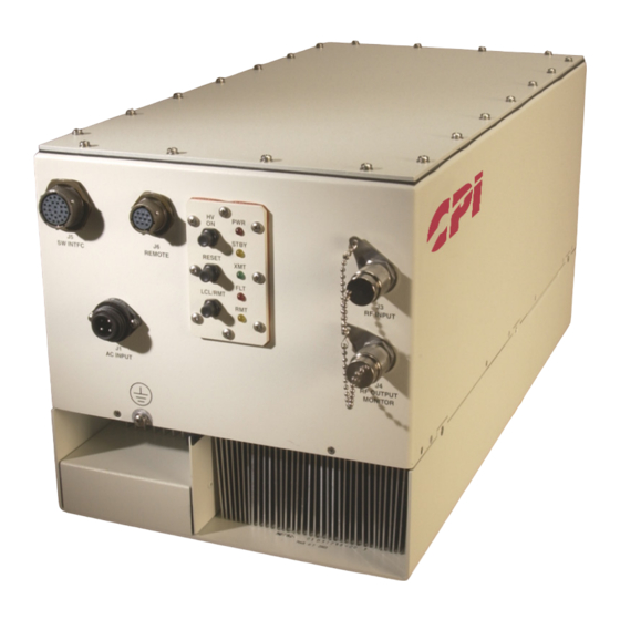
MPA Hub Mount
Service Center Headquarters and Design Center
West Coast Operations
811 Hansen Way
Palo Alto, CA 94303
Manufacturing
East Coast Operations
45 River Drive
Georgetown, Ontario
Canada L7G 2J4
Doc. 01031254 Rev. 1
For Use With Model Numbers . . .
T04CO
T04UO
Advertisement
Table of Contents


Need help?
Do you have a question about the T04CO and is the answer not in the manual?
Questions and answers