Sign In
Upload
Manuals
Brands
CPI Manuals
Racks & Stands
T04CO
CPI T04CO Manuals
Manuals and User Guides for CPI T04CO. We have
1
CPI T04CO manual available for free PDF download: Installation & Operation Manual
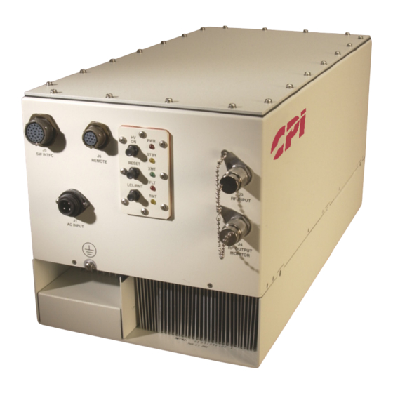
CPI T04CO Installation & Operation Manual (112 pages)
MPA Hub Mount
Brand:
CPI
| Category:
Racks & Stands
| Size: 4.72 MB
Table of Contents
Table of Contents
3
High Voltage Equipment
9
Introduction
9
Personnel Operating Guidelines
9
Safety
9
General Guidelines
10
When Is Voltage "High
10
Microwave Discussion
15
Microwave Radiation
15
Personnel Operating Guidelines
15
General Microwave Guidelines
16
Chapter 1 Introduction
17
Overview
17
Table 1-1. MPA Hub Mount Amplifiers
17
Figure 1-1. MPA Hub Mount
18
Optional Features
19
Figure 1-2. MPA Hub Mount RF Diagram
19
About this Manual
20
Conventions
21
Notes and Cautions
21
Warnings
21
Text Conventions
22
Chapter 2 Unpacking and Installation
23
Overview
23
Pre-Inspection
23
Unpacking
23
Installation
24
Amplifier Installation
24
Cooling Considerations
25
Electrical Power Connections
26
Prime Power
26
Grounding
26
Remote Control Interface
27
Figure 2-1. MPA Connector Locations
27
Figure 2-2. RS-232 Cables
28
Switch Interface Connector (J5)
29
RF Coaxial Cable Connections (J3, J4)
29
RF Output Waveguide Flange Connection (J8)
30
Figure 2-3. MPA Hub Mount Rear Panel
30
Chapter 3 Initial Power on and Checkout
33
Overview
33
Front Panel Controls and Indicators
34
Figure 3-1. Amplifier Front Panel Controls and Indicators
34
Table 3-1. Hub-Mount MPA Front Panel Controls and Indicators
35
Optional RCU Controls and Indicators
36
Remote Control Multi-Drop Operation
36
Figure 3-2. Remote Control Unit Front Panel
36
Control Keys
38
Figure 3-3. Remote Control Unit Control Keys
39
Display and LED Group
40
Figure 3-4. Display and LED Group
40
Figure 3-5. Remote Control Unit Menu Tree
41
First Time Pre-Power Procedure
42
Power on Sequence
43
Initial Check, High Voltage off
43
Check Factory Set Values Via a Computer
44
Check Factory Set Values Via RCU
44
Table 3-2. Helix and RF Settings Fault and Alarm Ranges
45
Initial Check, High-Voltage on
46
Verify RF Output
48
Setup for Operational Service
49
Chapter 4 External Interfaces
51
Overview
51
Control Mode Hierarchy
51
Serial Interface
52
Interface Configuration
52
RF Switch Interface (J5)
52
Relay Definitions
53
Table 4-1. RF Switch Pin Assignment (J5)
56
Chapter 5 Normal Operation
59
General
59
Overview of Operation
60
Normal Operating Procedures
61
LOCAL Mode Operation
61
Remote Control Mode, Computer Control
62
Shutdown
62
Normal Shutdown
62
Prime Power Interrupts
62
Making Routine Safety Checks
63
Description of Amplifier States
63
Post
64
Heater Time Delay (HTD)
64
Standby State
65
Beam on Sequence
65
Transmit State
65
Beam off Sequence
65
Fault State
66
Auto Fault Recycle Mode Rules
66
Fault Log
67
Chapter 6 Operator Maintenance
69
Introduction
69
Preventive Maintenance Tasks
69
Visual Inspection
70
Air System Maintenance
71
Other Preventive Maintenance Tasks
72
Customer Service
72
Chapter 7 Drawings
73
Customer Service
75
Telephone Directory
75
Return Procedure
76
Figure B-1 Startup Screen
79
Figure B-2. Meters Screen (in HTD
80
Figure B-3 no Communication Fault
80
Figure B-4 Communication Settings
81
Figure B-5 RF Control Screen
82
Figure B-6 Power Supply Settings
82
Figure B-7 Miscellaneous Screen
83
Figure B-8 RF Inhibit State
84
Figure B-9 Changing Parameters
84
Figure B-10 Meters Screen
85
Figure B-11 Fault Reporting
86
Figure B-12 Fault Log
87
Figure B-13 Optional Linearizer Settings
88
Figure B-14 WG Switch (F3) Is Active
88
Figure B-15 Switch System with Separate Input
89
Figure B-16 Switch System with Switched (Ganged) Input
89
Figure B-17 Switch System Type Setup
90
Appendix C Replaceable Parts
91
Appendix D Optional Linearizer Operation
93
Appendix E Optional L-Band BUC Operation
95
Figure F-1. Interconnect Diagram (Optional SW Controller
98
Table F-1 Drawings
98
Appendix G Optional Hybrid Switch Controller Operation
99
Figure G-1. Front View of the Sub System Front Panel
100
Figure G-2. Top View of the Switch Sub System
100
Table G-1 Pin out Specifications for
104
Table G-2 Pin out Specifications for M&C Interface
104
Table G-3 Cable Connections
107
Figure G-4 Switching and Combining State Diagram
109
Figure G-5 Switching and Combining State Diagram
109
Table G-4 Four Combiner States
110
Figure G-3. RF Block Diagram
111
Table G-5 Serial Commands and Arguments
111
Table G-6 Drawings
111
Advertisement
Advertisement
Related Products
CPI T04UO
CPI T02KO
CPI T03KO
CPI TRML Series
CPI TSR411
CPI TSR412A
CPI TSK100A
CPI TR Series
CPI TR10
CPI TR20
CPI Categories
Bank Note Validator
Amplifier
Cash Counters & Coin Sorters
Scooter
Antenna
More CPI Manuals
Login
Sign In
OR
Sign in with Facebook
Sign in with Google
Upload manual
Upload from disk
Upload from URL