
Related Manuals for Galil Motion Control DMC-21 5 Series

Summary of Contents for Galil Motion Control DMC-21 5 Series
- Page 1 USER MANUAL DMC-21x5 Manual Rev. 1.0a1 Galil Motion Control, Inc. 270 Technology Way Rocklin, California 916.626.0101 support@galil.com galil.com 12/2020...
- Page 2 Using This Manual This user manual provides information for proper operation of the DMC-21x5 controller. A separate supplemental manual, the Command Reference, contains a description of the commands available for use with this controller. It is recommended that the user download the latest version of the Command Reference and User Manual from the Galil Website.
-
Page 3: Table Of Contents
Contents Contents Chapter 1 Overview Introduction ........................1 Part Numbers ........................ 2 Overview of Motor Types ..................... 3 Overview of External Amplifiers .................. 4 Overview of Galil Amplifiers and Drivers ..............4 DMC-21x5 Functional Elements .................. 5 Chapter 2 Getting Started Elements Needed ...................... - Page 4 High Speed Position Capture (The Latch Function) ............ 77 Chapter 7 Application Programming Overview ........................78 Program Format ......................78 Executing Programs - Multitasking ................80 Debugging Programs ....................81 Program Flow Commands .................... 82 Mathematical and Functional Expressions ..............96 Variables ........................
- Page 5 Description ........................161 Electrical Specifications ....................162 Pin-outs ......................... 163 Servo Motor Operation ....................164 Error Monitoring and Protection ................... 166 External Amplifier Interface ..................167 Analog Inputs ........................ 168 A4 – SDM-20242 Description ........................169 Electrical Specifications ....................170 Pin-outs .........................
-
Page 6: Chapter 1 Overview
Chapter 1 Overview Introduction The DMC-21x5 series is the latest in Galil's Econo line of motion controllers and is an upgraded version of the popular DMC-21x3 series controller. The controller series offers many enhanced features compared to prior generation controllers including high speed communications, non-volatile program memory, faster encoder speeds, and improved command processing. -
Page 7: Part Numbers
Part Numbers The DMC controller board comes in two sizes, 1-4 axis models (labeled A-D) and 5-8 axis models (labeled E-H). The number of axis is designated by x in the part number DMC-21x5. The full DMC-21x5 part number is a combination of the DMC controller part number (DMC-21x5), controller board options, and optional accessory types, where Y is option for the controller or accessory. -
Page 8: Overview Of Motor Types
Accessory Options Option Type Options Brief Description Documentation 20341 20 W brush-type only drive A1 – AMP-20341, pg 151 20440 200 W brush-type only drive A2 – AMP-20440, pg 155 20540/20520 500 W trapazoidal servo drive A3 – AMP-20545/20525, pg 161 2 and 4-axis models 20242 Configurable microstepping drive... -
Page 9: Overview Of External Amplifiers
Stepper Motor with Step and Direction Signals The DMC-21x5 can control stepper motors. In this mode, the controller provides two signals to connect to the stepper motor: Step and Direction. For stepper motor operation, the controller does not require an encoder and operates the stepper motor in an open loop fashion. Chapter 2 describes the proper connection and procedure for using stepper motors. -
Page 10: Dmc-21X5 Functional Elements
DMC-21x5 Functional Elements The DMC-21x5 circuitry can be divided into the following functional groups as shown in Figure 1.2 and discussed below. Figure 1.2: DMC-21x5 Functional Elements DMC-21x5 The main processing unit of the controller is a specialized Microcomputer with RAM and Flash EEPROM. The RAM provides memory for variables, array elements, and application programs. - Page 11 as additional inputs (2 inputs / each axis). The general inputs as well as the index pulse can also be used as high speed latches for each axis. A high speed encoder compare output is also provided. The DMC-2155 through DMC-2185 controller provides an additional 8 inputs and 8 outputs. 2185 System Elements As shown in Figure 1.3, the DMC-21x5 is part of a motion control system which includes amplifiers, motors and...
- Page 12 Encoder An encoder translates motion into electrical pulses which are fed back into the controller. The DMC-21x5 accepts feedback from either a rotary or linear encoder. Typical encoders provide two channels in quadrature, known as MA and MB. This type of encoder is known as a quadrature encoder. Quadrature encoders may be either single- ended (MA and MB) or differential (MA+, MA- and MB+, MB-).
-
Page 13: Chapter 2 Getting Started
Chapter 2 Getting Started Elements Needed For a complete system, Galil recommends the following elements: 1. DMC-21x5 series motion controller 2. Motor Amplifiers (integrated when using Galil amplifiers) 3. Power Supply for controller and amplifiers 4. Brushed or brushless servo motors with encoders or stepper motors 5. -
Page 14: Layout
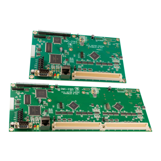
Layout DMC-2145 Dimensions Figure 2.1: DMC-21x5 Dimensions (inches) where x is 1 through 4 axes DMC-2185 Dimensions Figure 2.2: DMC-21x5 Dimensions (inches) where x is 5 through 8 axes Chapter 2 Getting Started ▫ 9 DMC-21x5 User Manual 1.0a1... -
Page 15: Installing The Dmc, Amplifiers, And Motors
Installing the DMC, Amplifiers, and Motors Installation of a complete, operational motion control system consists of the following steps: Step 1. Connecting Encoder Feedback, pg 11 Optional for steppers Step 2a. Wiring Motors to Galil's Amplifiers, pg 12 Internal Amplifiers only Step 2b. - Page 16 Step 1. Connecting Encoder Feedback The type of feedback the controller is capable of interfacing with depends on the additional options ordered for the controller. Table 2.1 shows the different encoder feedback types available for the DMC-21x5 including which options are required. Note that each feedback type has a different configuration command. See the Command Reference for full details on how to properly configure each axis.
- Page 17 Step 2a. Wiring Motors to Galil's Amplifiers If an external amplifier is being used, proceed to Step 2b. Connecting External Amplifiers and Motors. Table 2.2 below provides a general overview of the connections required for connecting different types of motors to Galil internal amplifiers.
- Page 18 Step 2b. Connecting External Amplifiers and Motors System connection procedures will depend on system components and motor types. Any combination of motor types can be used with the DMC-21x5. There can also be a combination of axes running from Galil integrated amplifiers and drivers and external amplifiers or drivers.
- Page 19 Once the amplifier enable signal is correctly wired, issuing an will disable the amplifier and an will enable it. Step C. Connect the command signals The DMC-21x5 has two ways of controlling amplifiers: 1. Using a motor command line (±10V analog output). The motor and the amplifier may be configured in torque or velocity mode.
- Page 20 Controller or amplifier power should never be plugged in HOT. Always power down the power supply WARNING before installing or removing power connector(s) to/from controller or amplifier. For more information regarding connector type and part numbers see Power Connector Part Numbers, pg 141. The power specifications for the controller are provided in Power Requirements, pg 136 and the power specifications for each amplifier are found under their specific section in the appendix, see Accessory Components, pg 149.
- Page 21 Step 6. Setting Safety Features Step A. Setting Amplifier Gains A transconductance (current) amplifier takes a ±10V command signal and produces a current in the motor proportional to that signal. This ratio is the amplifier gain (amps/volts) and can be set via the Amplifier Gain (AG) command when using Galil's internal amplifiers.
- Page 22 Step 7. Tune the Servo System Adjusting the tuning parameters is required when using servo motors. The controller's default set of PID's are not optimized and should not be used in practice. For the theory of operation and a full explanation of all the PID and other filter parameters, see Chapter 10 Theory of Operation, pg 124.
-
Page 23: Chapter 3 Connecting Hardware
Chapter 3 Connecting Hardware Overview The DMC-21x5 provides a variety of dedicated inputs such as forward limit, reverse limit, home, and Abort signals. as well as general purpose The DMC-21x5 provides digital inputs for forward limit, reverse limit, home, and Abort signals. The controller also has 8 general purpose uncommitted inputs as well as 8 outputs. -
Page 24: Overview Of Inputs
Overview of Inputs General Purpose Digital Inputs The DMC-21x5 inputs are rated for 5V. The amount of inputs available on the DMC-21x5 depends on the number of axes on the controller. For example, 1-4 axis models come with a single bank of 8 inputs, Bank 0 (DI[8:1]). 5-8 axis models come with an additional bank of 8 inputs, Bank 1 (DI[16:9]), for a total of 16 inputs. - Page 25 Each input from the auxiliary encoder is a differential line receiver and can accept voltage levels between ±12 V. The inputs have been configured to accept TTL level signals. To connect TTL signals, simply connect the signal to the + input and leave the - input disconnected. For other signal levels, the '-' input should be connected to a voltage that is ~½...
- Page 26 The Home input detects any transition in the state of the switch and toggles between logic states 0 and 1 at every transition. There are three homing routines supported by the DMC-21x5: Find Edge (FE), Find Index (FI), and Standard Home (HM).
-
Page 27: Overview Of Outputs
Reset Input/Reset Button When the Reset input is triggered the controller will be reset. The Reset input and reset button will not master reset the controller unless the MRST jumper is installed during a controller reset. The Reset input is an active low signal. -
Page 28: External Amplifier Interface
External Amplifier Interface External Servo Control The DMC-21x5 command voltage ranges between ±10V and is output on the motor command line. This signal, along with GND, provides the input to the motor amplifiers. The amplifiers must be sized to drive the motors and load. -
Page 29: Chapter 4 Software Tools And Communication
Chapter 4 Software Tools and Communication Introduction The default configuration DMC-21x5 has one one RS-232 port and one Ethernet port. The Ethernet port is a 10/100BASE-T connection that auto-negotiates the speed and half or full duplex. The GDK software package is available for PC computers running Microsoft Windows or Linux to communicate with the DMC-21x5 controller. -
Page 30: Unsolicited Messages Generated By Controller
Unsolicited Messages Generated by Controller When the controller is executing a program, it may generate responses which will be sent via the RS-232 port or Ethernet handles. This response could be generated as a result of messages using the command or as a result of a command error. -
Page 31: Ethernet Configuration
Ethernet Configuration Communication Protocols The Ethernet is a local area network through which information is transferred in units known as packets. Communication protocols are necessary to dictate how these packets are sent and received. The DMC-21x5 supports two industry standard protocols, TCP/IP and UDP/IP. The controller will automatically respond in the format in which it is contacted. - Page 32 Be sure that there is only one DHCP server running. If the network has DHCP running, it may automatically assign an IP address to the DMC controller upon linking it to the network. In order to WARNING ensure that the IP address is correct, please contact the system administrator before connecting the I/O board to the Ethernet network.
-
Page 33: Data Record
network. ARP is an application that determines the Ethernet (hardware) address of a device at a specific IP address. Ping is used to check the communication between the device at a specific IP address and the host computer. The DMC-21x5 can communicate with a host computer through any application that can send TCP/IP or UDP/IP packets. - Page 34 Axis Information ADDR TYPE ITEM ADDR TYPE ITEM 44-45 A axis status – see bit field map below 156-157 E axis status – see bit field map below A axis switches – see bit field map below E axis switches – see bit field map below A axis stop code E axis stop code 48-51...
- Page 35 Data Record Bit Field Maps Header Information - Byte 0, 1 of Header: BIT 15 BIT 14 BIT 13 BIT 12 BIT 11 BIT 10 BIT 9 BIT 8 I Block Present T Block Present S Block Present in Data Record in Data Record in Data Record BIT 7...
-
Page 36: Galil Software
Notes Regarding Velocity and Torque Information The velocity information that is returned in the data record is 64 times larger than the value returned when using the command (Tell Velocity). See command reference for more information about TV. The Torque information is represented as a number in the range of ±32767. Maximum negative torque is -32767. Maximum positive torque is 32767. -
Page 37: Chapter 5 Command Basics
Chapter 5 Command Basics Introduction The DMC-21x5 provides over 100 commands for specifying motion and machine parameters. Commands are included to initiate action, interrogate status and configure the digital filter. These commands are sent in ASCII. The DMC-21x5 instruction set is BASIC-like and easy to use. Instructions consist of two uppercase letters that correspond phonetically with the appropriate function. - Page 38 For specifying data for the A,B,C and D axes, commas are used to separate the axes. If no data is specified for an axis, a comma is still needed as shown in the examples below. If no data is specified for an axis, the previous value is maintained.
-
Page 39: Controller Response To Data
Controller Response to DATA The DMC-21x5 returns a : for valid commands and a ? for invalid commands. For example, if the command is sent in lower case, the DMC-21x5 will return a ?. invalid command, lower case DMC-21x5 returns a ? When the controller receives an invalid command the user can request the error code. - Page 40 Interrogating Current Commanded Values. Most commands can be interrogated by using a question mark (?) as the axis specifier. Type the command followed by a ? for each axis requested. ?,?,?,? Request A,B,C,D values Request B value only The controller can also be interrogated with operands. Operands Most DMC-21x5 commands have corresponding operands that can be used for interrogation.
-
Page 41: Chapter 6 Programming Motion
Chapter 6 Programming Motion Overview The DMC-21x5 provides several modes of motion, including independent positioning and jogging, coordinated motion, electronic cam motion, and electronic gearing. Each one of these modes is discussed in the following sections. The DMC-2115 are single axis controllers and use A axis motion only. Likewise, the DMC-2125 use A and B, the DMC-2135 use A, B, and C, and the DMC-2145 use A,B,C, and D. -
Page 42: Independent Axis Positioning
Following a trajectory based on a master Electronic Cam encoder position Smooth motion while operating in independent Motion Smoothing axis positioning Smooth motion while operating in vector or Motion Smoothing linear interpolation positioning Smooth motion while operating with stepper Stepper Motion Smoothing motors Gantry - two axes are coupled by gantry Electronic Gearing - Example - Gantry Mode... - Page 43 Operand Summary - Independent Axis OPERAND DESCRIPTION _ACm Return acceleration rate for the axis specified by 'm' _DCm Return deceleration rate for the axis specified by 'm' _SPm Returns the speed for the axis specified by 'm' _PAm Returns the last commanded position for the 'm' axis _PRm Returns current incremental distance specified for the 'm' axis _TVm...
-
Page 44: Independent Jogging
Figure 6.1: Velocity Profiles of ABC axes The A and B axes have a 'trapezoidal' velocity profile, while the C axis has a 'triangular' velocity profile. The A and B axes accelerate to the specified speed, move at this constant speed, and then decelerate such that the final position agrees with the command position, PR. -
Page 45: Position Tracking
Example - Jog in A only Jog A motor at 50000 count/s. After A axis is at its jog speed, begin jogging C in reverse direction at 25000 count/s. 'program label 'servo A and C axes 20000,,20000; 'specify A, C acceleration of 20000 counts/sec2 20000,,20000;... - Page 46 specified by AC, DC, and SP. Updating the position target at a specific rate will not allow the user to create a custom profile. The following example will demonstrate the possible different motions that may be commanded by the controller in the position tracking mode.
- Page 47 Example - Motion 2: The previous step showed the plot if the motion continued all the way to 5000, however partway through the motion, the object that was being tracked changed direction, so the host program determined that the actual target position should be 2000 counts at that time.
- Page 48 Example - Motion 3: In this motion, the host program commands the controller to begin motion towards position 5000, changes the target to -2000, and then changes it again to 8000. Figure 6.4 shows the plot of position vs. time and velocity vs. time.
-
Page 49: Linear Interpolation Mode
Note the controller treats the point where the velocity passes through zero as the end of one move, and the beginning of another move. is allowed, however it will introduce some time delay. Trippoints Most trippoints are valid for use while in the position tracking mode. There are a few exceptions to this; the commands may not be used while in this mode. - Page 50 stop motion instantly at the last vector. There will be no controlled deceleration. returns the available spaces for segments that can be sent to the buffer. 511 returned means the buffer is empty and 511 segments can be sent. A zero means the buffer is full and no additional segments can be sent. As long as the buffer is not full, additional segments can be sent at PC bus speeds.
- Page 51 The second function, > m, requires the vector speed to reach the value m at the end of the segment. Note that the function > m may start the deceleration within the given segment or during previous segments, as needed to meet the final speed requirement, under the given values of and VD.
- Page 52 Operand Summary - Linear Interpolation OPERAND DESCRIPTION _AVm Return distance traveled _CSm Returns number of the segment in the sequence, starting from 0 _LEm Returns length of vector (resets after 2147483647) Returns number of available spaces for linear segments in the sequence buffer _LMm 0 means buffer full, 511 means buffer empty _VPm...
- Page 53 Figure 6.6: Linear Interpolation Example - Multiple Moves This example makes a coordinated linear move in the AB plane. The Arrays are used to store 750 incremental distances which are filled by the program #load. #load; 'label for load program va [750],vb [750];...
-
Page 54: Vector Mode: Linear And Circular Interpolation Motion
Vector Mode: Linear and Circular Interpolation Motion The DMC-21x5 allows a long 2-D path consisting of linear and arc segments to be prescribed. Motion along the path is continuous at the prescribed vector speed even at transitions between linear and circular segments. The DMC-21x5 performs all the complex computations of linear and circular interpolation, freeing the host PC from this time intensive task. - Page 55 Additional commands The commands VS, VA, and are used for specifying the vector speed, acceleration, and deceleration. is the s curve smoothing constant used with coordinated motion. Specifying Vector Speed for Each Segment: The vector speed may be specified by the immediate command VS. It can also be attached to a motion segment with the instructions <...
- Page 56 Example: Assume an XY table with the Z axis controlling a knife. The Z-axis has a 2000 quad counts/rev encoder and has been initialized after power-up to point the knife in the +Y direction. A 180° circular cut is desired, with a radius of 3000, center at the origin and a starting point at (3000,0).
- Page 57 Operand Summary - Coordinated Motion Sequence OPERAND DESCRIPTION _VPm The absolute coordinate of 'm' axis at the last intersection along the sequence _AVm Contains the vector distance from the start of the sequence for the 'm' coordinate system Number of available spaces for linear and circular segments in DMC-21x5 sequence buffer _LMm 0 means buffer is full, 511 means buffer is empty _CSm...
- Page 58 Vector Mode - Mathematical Analysis The terms of coordinated motion are best explained in terms of the vector motion. The vector velocity, VS, which is also known as the feed rate, is the vector sum of the velocities along the A and B axes, VA and VB. √...
- Page 59 The velocity profile may be specified independently in terms of the vector velocity and acceleration. For example, the velocity profile corresponding to the path of Figure 6.8 may be specified in terms of the vector speed and acceleration. VS 100000 VA 2000000 The resulting vector velocity is shown in Figure 6.9.
-
Page 60: Electronic Gearing
time Figure 6.10: Vector and Axes Velocities Electronic Gearing This mode allows up to 8 axes to be electronically geared to some master axes. The masters may rotate in both directions and the geared axes will follow at the specified gear ratio. The gear ratio may be different for each axis and changed during motion. - Page 61 initial shock to the slave axis. Figure 6.11 below shows the velocity vs. time profile for instantaneous gearing. Figure 6.12 shows the velocity vs. time profile for the gradual gearing engagement. Figure 6.11: Velocity counts/sec vs. Time (msec) Instantaneous Gearing Engagement Figure 6.12: Velocity (counts/sec) vs.
- Page 62 Using the ramped gearing, the slave will engage gearing gradually. Since the gearing is engaged over the interval of 6000 counts of the master, the slave will only travel ~3396 counts and ~135 counts respectively. The difference between these two values is stored in the _GPm operand.
-
Page 63: Electronic Cam
Example - Gantry Mode In applications where both the master and the follower are controlled by the DMC-21x5 controller, it may be desired to synchronize the follower with the commanded position of the master, rather than the actual position. This eliminates the coupling between the axes which may lead to oscillations. For example, assume that a gantry is driven by A and B axes on both sides. - Page 64 Step 2. Specify the master cycle and the change in the slave axis (or axes). In the electronic cam mode, the position of the master is always expressed modulo one cycle. In this example, the position of A is always expressed in the range between 0 and 6000. Similarly, the slave position is also redefined such that it starts at zero and ends at 1500.
- Page 65 Figure 6.13: Electronic Cam Example This disengages the slave axis at a specified master position. If the parameter is outside the master cycle, the stopping is instantaneous. To illustrate the complete process, consider the cam relationship described by the equation: A+100sin 0.18 A where A is the master with a cycle of 2000 counts.
- Page 66 #run; 'label 'enable cam ,500; 'starting position ,5000; 'set speed for B axis 'servo A and B axes 'move B axis 'wait until B axis motion is completed 'wait for start signal ,1000; 'engage slave –1; 'wait for stop signal ,1000;...
- Page 67 Example - Electronic CAM The following example illustrates a cam program with a master axis, Z, and two slaves, A and Y. #a;v1=0; 'label; initialize variable ABC; 'enable A and B axes 0,0; 'go to position 0,0 on A and B axes 'C axis as the Master for ECAM 0,0,4000;...
-
Page 68: Contour Mode
Contour Mode The DMC-21x5 also provides a contouring mode. This mode allows any arbitrary position curve to be prescribed for 1 to 8 axes. This is ideal for following computer generated paths such as parabolic, spherical or user-defined profiles. The path is not limited to straight line and arc segments and the path length may be infinite. Specifying Contour Segments The Contour Mode is specified with the CM command. - Page 69 Additional Commands gives the amount of space available in the contour buffer (511 maximum). Zero parameters for followed by zero parameters for will exit the contour mode. If no new data is found and the controller is still in the contour mode, the controller waits for new data. No new motion commands are generated while waiting.
- Page 70 The DMC-21x5 can compute trigonometric functions. However, the argument must be expressed in degrees. Using our example, the equation for X is written as: X = 50T - 955 sin 3T A complete program to generate the contour movement in this example is given below. Contour Mode Example #points;...
-
Page 71: Virtual Axis
Record and Playback Example: #record; 'begin 'program apos[501]; 'dimension array with 501 elements apos[]; 'specify automatic record _TPA; 'specify A position to be captured 'turn A motor off 'begin recording at 4 msec interval (at TM1000) 'continue until done recording #a,(_RC=1);... -
Page 72: Stepper Motor Operation
Sinusoidal Motion Example The A axis must perform a sinusoidal motion of 10 cycles with an amplitude of 1000 counts and a frequency of 20 This can be performed by commanding the A and N axes to perform circular motion. Note that the vector speed must be VS=2π... - Page 73 Monitoring Generated Pulses vs. Commanded Pulses For proper controller operation, it is necessary to make sure that the controller has completed generating all step pulses before making additional moves. This is most important when back and forth motion is commanded. For example, when operating with servo motors, the trippoint (After Motion) is used to determine when the motion profiler is complete and is prepared to execute a new motion command.
-
Page 74: Stepper Position Maintenance Mode (Spm)
Command Summary - Stepper Motor Operation COMMAND DESCRIPTION Define Reference Position and Step Count Register Define Encoder Position when using an encoder Motion Profile Smoothing, Independent Time Constant Stepper Motor Smoothing Motor Type (2,-2,2.5 or -2.5 for stepper motors) Report Commanded Position Report number of step pulses generated by controller Tell Position of Encoder Table 6.14: List of commands related to Stepper motor operation... - Page 75 When a Galil controller is configured for step motor operation, the step pulse output by the controller is internally fed back to the auxiliary encoder register. For SPM the feedback encoder on the stepper will connect to the main encoder port. Enabling the SPM mode on a controller with executes an internal monitoring of the auxiliary and main encoder registers for that axis or axes.
- Page 76 Example: Error Correction The following code demonstrates what is necessary to set up SPM mode for the A axis, detect error, stop the motor, correct the error, and return to the main code. The drive is a full step drive, with a 1.8 step motor and 4000 count/rev encoder.
-
Page 77: Dual Loop (Auxiliary Encoder)
Example: Friction Correction The following example illustrates how the SPM mode can be useful in correcting for A axis friction after each move when conducting a reciprocating motion. The drive is a 1/64th microstepping drive with a 1.8 step motor and 4000 count/rev encoder. - Page 78 while the the command returns the current position of the auxiliary encoders. The command configures the auxiliary encoder to be used for dual loop control. Backlash Compensation There are two methods for backlash compensation using the auxiliary encoders: continuous dual loop and sampled dual loop.
-
Page 79: Motion Smoothing
Motion Smoothing The DMC-21x5 controller allows the smoothing of the velocity profile to reduce the mechanical vibration of the system. Trapezoidal velocity profiles have acceleration rates which change abruptly from zero to maximum value. The discontinuous acceleration results in jerk which causes vibration. The smoothing of the acceleration profile leads to a continuous acceleration profile and reduces the mechanical shock and vibration. -
Page 80: Homing
Using the KS Command (Step Motor Smoothing): When operating with step motors, motion smoothing can be accomplished with the command, KS. command smoothes the frequency of step motor pulses. Similar to the command IT, this produces a smooth velocity profile. The smoothing parameter used is a number between 0.5 and 128 and determines the degree of filtering. - Page 81 Direction of Motion Switch Type CN Setting Initial _HMA state Stage 1 Stage 2 Stage 3 CN,-1 Normally Open Reverse Forward Forward Normally Open CN,1 Forward Reverse Forward Normally Closed CN,-1 Forward Reverse Forward CN,1 Normally Closed Reverse Forward Forward Table 6.17: Possible directions of motions for each stage of the Home command Example: Homing #home;...
-
Page 82: High Speed Position Capture (The Latch Function)
Example: Find Edge #edge; 'label 2000000; 'acceleration rate 2000000; 'deceleration rate 8000; 'speed 'enable A axis 'find edge command 'begin motion 'after complete "FOUND HOME"; 'send message 'define position as 0 'disable A axis 'end program Command Summary - Homing Operation COMMAND DESCRIPTION Defines motion that searches for the Home Input... -
Page 83: Chapter 7 Application Programming
Chapter 7 Application Programming Overview The DMC-21x5 provides a powerful programming language that allows users to customize the controller for their particular application. Programs can be downloaded into the DMC-21x5 memory freeing the host computer for other tasks. However, the host computer can send commands to the controller at any time, even while a program is being executed. - Page 84 #begin1 Invalid labels #1Square #123 A Simple Example Program: #start; 'beginning of the program 'enable A and B axes #loop; 'label for loop 10000,20000; 'specify relative distances on A and B axes 'begin motion 'wait for motion complete 2000; 'wait 2 sec #loop;...
-
Page 85: Executing Programs - Multitasking
The DMC-21x5 provides a command, NO, for commenting programs or single apostrophe. This command allows the user to include up to 78 characters on a single line after the command and can be used to include comments from the programmer as in the following example: #path '2D circular path 'vector motion on A and B... -
Page 86: Debugging Programs
'wait until motion is completed 'wait 10 msec #loop2,(@IN[2]=1); 'jump to #loop2 label while Input 2 is not active 'halt all threads 'end program The program above is executed with the command #task2,0 which designates task2 as the main thread (i.e. Thread 0). -
Page 87: Program Flow Commands
OPERAND DESCRIPTION _ED0 Contains the last line of program execution Contains the number of available labels Contains the number of available variables Contains the number of available arrays Contains the number of available array elements Table 7.2: List of operands related to memory on the DMC-21x5 Debugging Example The following program has an error. - Page 88 DMC-21x5 Event Triggers COMMAND DESCRIPTION Pauses code until motion is complete on the specified axes or motion sequence Pauses code until reference position has reached the specified relative distance from the start of the move, only one axis may be specified at a time Pauses code until after specified distance from the last AR or AD command has elapsed, only one axis may be specified at a time Pauses code until after absolute position occurs, only one axis may be specified at a time...
- Page 89 Event Trigger - Repetitive Position Trigger To set the output every 10000 counts during a move, the trippoint is used as shown in the next example. #trip; 'program label 50000; 'specify jog speed 'enable A axis A;n=0; 'begin motion, create counter variable #loop;...
- Page 90 Event Trigger - Change Speed along Vector Path The following program changes the feed rate or vector speed at the specified distance along the vector. The vector distance is measured from the start of the move or from the last command.
- Page 91 Conditional Jumps The DMC-21x5 provides Conditional Jump (JP) and Conditional Jump to Subroutine (JS) instructions for branching to a new program location based on a specified condition. The conditional jump determines if a condition is satisfied and then branches to a new location or subroutine. Unlike event triggers, the conditional jump instruction does not halt the program sequence.
- Page 92 For example, using variables named v1, v2, v3 and v4: #test,((v1<v2)&(v3<v4)) In this example, this statement will cause the program to jump to the label #test if v1 is less than v2 and v3 is less than v4. To illustrate this further, consider this same example with an additional condition: #test,(((v1<v2)&(v3<v4)) | (v5<v6)) This statement will cause the program to jump to the label #TEST under two conditions;...
- Page 93 Using the ELSE Command command is an optional part of an IF conditional statement and allows for the execution of command ELSE only when the argument of the command evaluates False. The command must occur after an ELSE command and has no arguments. If the argument of the command evaluates false, the controller will skip commands until the command.
- Page 94 Subroutines A subroutine is a group of instructions beginning with a label and ending with an command. Subroutines are called from the main program with the jump subroutine instruction JS, followed by a label or line number, and conditional statement. After the subroutine is executed, the program sequencer returns to the program location where the subroutine was called unless the subroutine stack is manipulated as described in the following section.
- Page 95 Automatic Subroutines for Monitoring Conditions Often it is desirable to monitor certain conditions continuously without tying up the host or DMC-21x5 program sequences. The controller can monitor several important conditions in the background. These conditions include checking for the occurrence of a limit switch, a defined input, position error, or a command error. Automatic monitoring is enabled by inserting a special, predefined label in the applications program.
- Page 96 Example - Position Error #loop; 'dummy program #loop; 'loop #POSERR; 'position error routine v1=_TEA; 'read position error "EXCESS POSITION 'print message ERROR"; "ERROR=",v1; 'print error 1000; 'return from error download program :XQ #LOOP execute dummy program :JG 100000 jog at high speed :BGA begin motion Example - Input Interrupt...
- Page 97 Example - Command Error #main; 'begin main program speed=2000; 'set variable for speed speed; 'define jog speed 'enable A axis 'begin motion #loop; 'label for loop speed; 'update jog speed based upon speed variable 100; 'wait #loop; 'jump to #loop label 'end main program #CMDERR;...
- Page 98 Example - Communication Interrupt A DMC-2115 is used to move the A axis back and forth from 0 to 10000. This motion can be paused, resumed and stopped via input from the serial port. #main; 'label for main of program 'setup communication interrupt for serial port {P1}"Type 0 to stop 'send message to serial port...
- Page 99 4. Please refer to the JS command in the controller's command reference for further important information. Example: A Simple Adding Function #add; 'label for main program #sum(1,2,3,4,5,6,7,8) 'call subroutine and pass values MG_JS 'print return value #sum '(^a,^b,^c,^d,^e,^f,^g,^h) syntax note for use EN,, 'return sum (^a+^b+^c+^d+^e+^f+^g+^h)
- Page 100 Example: Local Scope #main; 'label for main program #power(2,2); 'call power subroutine to calculate 2^2 _JS; 'message returned value #power(2,16); 'call power subroutine to calculate 2^2 _JS; 'message returned value #power(2,-8); 'call power subroutine to calculate 2^2 _JS; 'message returned value #power;...
-
Page 101: Mathematical And Functional Expressions
General Program Flow and Timing information This section will discuss general programming flow and timing information for Galil programming. WT vs AT and coding deterministic loops The main difference between is that will hold up execution of the next command for the specified time from the execution of the command, will hold up execution of the next command for the specified time... - Page 102 Using basic mathematics it is known that 1.4*(80,000) = 112,000. However, using a terminal, a DMC controller would calculate the following: :var=1.4*80000 :MG var 111999.5117 The reason for this error relies in the precision of the controller. 1.4 must be stored to the nearest multiple of 1/65536, which is 91750/65536 = 1.3999.
-
Page 103: Variables
len6 {S4}; Response from command len5 {S4}; Response from command len4 {S4}; Response from command len3 {S4}; Response from command len2 {S4}; Response from command len1 {S4}; Response from command This program will accept a string of up to 6 characters, parse each character, and then display each character. Notice also that the values used for masking are represented in hexadecimal (as denoted by the preceding '$'). - Page 104 Programmable Variables The DMC-21x5 allows the user to create up to 510 variables. Each variable is defined by a name which can be up to eight characters. The name must start with an alphabetic character; however, numbers are permitted in the rest of the name.
-
Page 105: Operands
Example - Using Variables for Joystick The example below reads the voltage of an X-Y joystick and assigns it to variables vA and vB to drive the motors at proportional velocities, where: 10 Volts = 3000 rpm = 200000 c/sec Speed/Analog input = 200000/10 = 20000 #joystik;... -
Page 106: Arrays
OPERAND DESCRIPTION _BGm Contains the status of motion on the 'm' axis Contains the serial number of the controller Contains the number of available array names Contains the number of available labels Contains the number of available array elements Contains the status of the Home Switch for the 'm' axis _HMm _LFm Contains the status of the Forward Limit Switch for the 'm' axis... - Page 107 Using a Variable to Address Array Elements An array element number can also be a variable. This allows array entries to be assigned sequentially using a counter. #main; 'program labe count=0; 'initialize counter variable pos[10]; 'dimension array #loop; 'loop label 'wait 10 msec pos[count]=_TPA;...
-
Page 108: Input Of Data (Numeric And String)
Operand Summary - Automatic Data Capture OPERAND DESCRIPTION Contains recording status Contains the address of the next element for recording Example - Recording into An Array During a position move, store the A and Y positions and position error every 2 msec. #record;... - Page 109 #COMINT label is used for the communication interrupt. For example, the DMC-21x5 can be configured to interrupt on any character received on Port 2. The #COMINT subroutine is entered when a character is received and the subroutine can decode the characters. At the end of the routine the command is used.
-
Page 110: Output Of Data (Numeric And String)
Output of Data (Numeric and String) Numerical and string data can be output from the controller using several methods. The message command, MG, can output string and numerical data. Also, the controller can be commanded to return the values of variables and arrays, as well as other information using the interrogation commands (the interrogation commands are described in chapter 5). - Page 111 MG"counts/sec"; 'end program Using the MG Command to Configure Terminals The MG command can be used to configure a terminal. Any ASCII character can be sent by using the format {^n} where n is any integer between 1 and 255. MG{^07}{^255};...
- Page 112 Hex values are returned preceded by a $ and in 2's complement. Hex values should be input as signed 2's complement, where negative numbers have a negative sign. The default format is PF 10.0. :LZ 0 'disable suppressing leading zeroes :PF 10 'set format to 10 places :DP 21...
- Page 113 :v1=? 'return v1 $0A.00 :VF1 'change format :v1=? 'return v1 Local Formatting of Variables commands are global format commands that affect the format of all relevant returned values and variables. Variables may also be formatted locally. :VF 10.4 'set default variable format :v1=10 'assign v1 variable :v1=...
-
Page 114: Hardware I/O
acc=0; 'initialize acc variable #acc; 'label for loop #acc,(acc=0); 'jump back to acc label if variable is unchanged acc*cts/(2*3.14); 'convert to counts/sec 'enable A axis 'begin motion 'wait for motion to finish 'disable A axis 'end program Hardware I/O Digital Outputs The DMC-21x5 has an 8-bit uncommitted output port, the DMC-2155 through DMC-2185 has an additional 8 outputs. - Page 115 Digital Inputs The general digital inputs for are accessed by using the function or the command. The @IN[n] @IN[n] function returns the logic level of the specified input, n, where n is a number 1 through 16. Example - Using Inputs to control program flow #main,(@IN[1]=0);...
- Page 116 A low input on any of the specified inputs will cause automatic execution of the #ININT subroutine. The Return from Interrupt (RI) command is used to return from this subroutine to the place in the program where the interrupt had occurred. NOTE: Use the command, not EN, to return from the #ININT...
- Page 117 Example - Position Follower (Point-to-Point) The motor must follow an analog signal. When the analog signal varies by 10V, motor must move 10000 counts. Read the analog input and command A to move to that point. #points; 'label for main program 7000;...
-
Page 118: Example Applications
Example Applications Wire Cutter An operator activates a start switch. This causes a motor to advance the wire a distance of 10". When the motion stops, the controller generates an output signal which activates the cutter. Allowing 100 ms for the cutting completes the cycle. - Page 119 X-Y Table Controller An X-Y-Z system must cut the pattern shown in Figure 7.2. The X-Y table moves the plate while the Z motor raises and lowers the cutting tool. The solid curves in Figure 7.2 indicate sections where cutting takes place. Those must be performed at a feed rate of 1 inch per second.
- Page 120 #main; 'main program label ABC; 'enable A, B, and C axes 'select A and B axes for Vector Mode 160000,160000; 'define vector position 'end vector sequence 200000; 'set vector speed 1544000; 'set vector acceleration 'begin vector motion 'wait for motion to finish PRC=-80000;...
- Page 121 Speed = 20000 x @AN[] The corresponding velocity for the motor is assigned to a variable. #main; 'label for main program 'set starting jog speed 'enable A axis 'begin motion #loop; 'label for loop vel=@AN[1]*20000; 'read Analog Input 1 and calculate new speed vel;...
-
Page 122: Using The Dmc Editor To Enter Programs (Advanced)
Once there, the load position is read to find the position error and the controller commands the motor to move to a new rotary position which eliminates the position error. Since the required accuracy is 0.5 micron, the resolution of the linear sensor should preferably be twice finer. A linear sensor with a resolution of 0.25 micron allows a position error of ±2 counts. -
Page 123: Chapter 8 Hardware & Software Protection
Chapter 8 Hardware & Software Protection Introduction The DMC-21x5 provides several hardware and software features to check for error conditions and to inhibit the motor on error. These features help protect the various system components from damage. Machinery in motion can be dangerous! It is the responsibility of the user to design effective error handling and safety protection as part of the machine. -
Page 124: Software Protection
Input Protection Lines General Abort A low input stops commanded motion instantly without a controlled deceleration. For any axis in which the Off- On-Error function is enabled, the amplifiers will be disabled. This could cause the motor to coast to a stop. If the Off-On-Error function is not enabled, the motor will instantaneously stop and servo at the current position. - Page 125 Signal or Function State if Error Occurs #POSERR Jumps to automatic excess position error subroutine Error Light Turns on OE Function Shuts motor off if AEN Output Line Switches to Motor Off state The position error can be monitored during execution using the command.
- Page 126 'stop motion 'wait for motion to finish 'servo motor to clear error 'return to main program Limit Switch Routine The DMC-21x5 provides forward and reverse limit switches which inhibit motion in the respective direction. There is also a special label for automatic execution of a limit switch subroutine. The label specifies the start of #LIMSWI the limit switch subroutine.
-
Page 127: Chapter 9 Troubleshooting
Chapter 9 Troubleshooting Overview Potential problems have been divided into groups as follows: 1. Installation 2. Stability and Compensation 3. Operation 4. Error Light (Red LED) The various symptoms along with the cause and the remedy are described in the following tables. Installation SYMPTOM DIAGNOSIS... - Page 128 Stability SYMPTOM DIAGNOSIS CAUSE REMEDY Servo motor runs away when the Reversed Motor Type corrects Wrong feedback polarity. Reverse Motor or Encoder Wiring (remember loop is closed. situation ( to set Motor Type back to default value: Motor oscillates. Too high gain or too little Decrease .
-
Page 129: Chapter 10 Theory Of Operation
Chapter 10 Theory of Operation Overview The following discussion covers the operation of motion control systems. A typical motion control system consists of the elements shown in Figure 10.1. COMPUTER CONTROLLER DRIVER ENCODER MOTOR Figure 10.1: Elements of Servo Systems The operation of such a system can be divided into three levels , the levels are: 1. -
Page 130: Operation Of Closed-Loop Systems
This program corresponds to the velocity profiles shown in Figure 10.2. Note that the profiled positions show where the motors must be at any instant of time. Finally, it remains up to the servo system to verify that the motor follows the profiled position by closing the servo loop. -
Page 131: System Modeling
The results may be worse if the faucet is turned too fast. The overreaction results in temperature oscillations. When the response of the system oscillates, the system is unstable. Clearly, unstable responses are bad when a constant level is desired. What causes the oscillations? The basic cause for the instability is a combination of delayed reaction and high gain. - Page 132 1. Voltage Drive 2. Current Drive 3. Velocity Loop The operation and modeling in the three modes is as follows: Voltage Drive The amplifier is a voltage source with a gain of K [V/V]. The transfer function relating the input voltage, V, to the motor position, P, is ...
- Page 133 If the motor is a DC brushless motor, it is driven by an amplifier that performs the commutation. The combined transfer function of motor amplifier combination is the same as that of a similar brush motor, as described by the previous equations.
- Page 134 The model of the encoder can be represented by a gain of = 4N/2π [count/rad] For example, a 1000 lines/rev encoder is modeled as = 638 The DAC or D-to-A converter converts a 16-bit number to an analog voltage. The input range of the numbers is 65536 and the output voltage range is ±10V or 20V.
-
Page 135: System Analysis
K = 160 A = 0.9 C = 2 a = 250 rad/s and the equivalent continuous filter, G(s), is G(s) = [16 + 0.144s + 2000/s] · 250/ (s+250) , and two complex poles, p and p . The notch filter has two complex zeros, z and The effect of the notch filter is to cancel the resonance affect by placing the complex zeros on top of the resonance poles. - Page 136 Encoder = 4N/2π = 318 [count/rad] 2000/(s+2000) Digital Filter KP = 12.5, KD = 245, T = 0.001 Therefore, D(z) = 1030 (z-0.95)/Z Accordingly, the coefficients of the continuous filter are: P = 50 D = 0.98 The filter equation may be written in the continuous equivalent form: G(s) = 50 + 0.98s = .098 (s+51) The system elements are shown in Figure 10.6.
-
Page 137: System Design And Compensation
A(j200) = 390,000 (j200+51)/[(j200) 2 . (j200 + 2000)] α = Arg[A(j200)] = tan -1 (200/51)-180° -tan -1 (200/2000) α = 76° - 180° - 6° = -110° Finally, the phase margin, PM, equals PM = 180° + α= 70° As long as PM is positive, the system is stable. - Page 138 L(s) = M(s) K H(s) =3.17· 10 (s+2000)] Then the open loop transfer function, A(s), is A(s) = L(s) G(s) Now, determine the magnitude and phase of L(s) at the frequency ω c = 500. L(j500) = 3.17· 10 6 /[(j500) 2 (j500+2000)] This function has a magnitude of |L(j500)| = 0.00625 and a phase...
- Page 139 D = KD · T KD = D/T Assuming a sampling period of T=1ms, the parameters of the digital filter are: KP = 82.4 KD = 274 The DMC-21x5 can be programmed with the instruction: 82.4 In a similar manner, other filters can be programmed. The procedure is simplified by the following table, which summarizes the relationship between the various filters.
-
Page 140: Appendices
Appendices Electrical Specifications Electrical specifications are only valid once controller is out of reset. Servo Control Motor command line ± 10 V analog signal Resolution: 16-bit DAC or 0.0003 volts 3 mA maximum. Output impedance – 500 Ω Main and auxiliary encoder inputs ±... - Page 141 Auxiliary Inputs as Uncommitted Inputs: The auxiliary pins can be used as uncommitted inputs and are DI[96:81]* assigned to the following bits: Axis A: DI81, DI82 Axis B: DI83, DI84 Axis C: DI85, DI86 Axis D: DI87, DI88 Axis E: DI89, DI90 Axis F: DI91, DI92 Axis G: DI93, DI94 Axis H: DI95, DI96...
-
Page 142: Performance Specifications
Performance Specifications Minimum Servo Loop Update Time DMC-2115 through DMC-2185 250 μsec Position Accuracy ±1 quadrature count Velocity Accuracy Long Term Phase-locked, better than 0.005% Short Term System dependent Position Range ±2,147,483,647 counts per move Velocity Range Up to 15,000,000 counts/sec servo; 3,000,000 pulses/sec-stepper Velocity Resolution 2 counts/sec... -
Page 143: Ordering Options
Ordering Options Overview The DMC-21x5 can be ordered in many different configurations and with different options. This section provides information regarding the different options available on the DMC-21x5 motion controller and its accessory components. For information on pricing and how to order the controller with these options, see the DMC-21x5 part number generator on our website. - Page 144 HP – Horizontal Power Connector The HP option on the DMC-21x5 changes the orientation of the 6 pin power connector. By default, the power connector faces vertically from the board. With the HP option, the power connector faces horizontally. Part number ordering example: DMC-2165(UP,H,HP) RA –...
- Page 145 minus voltages rise at different rates during power up. This can be seen as an offset on the amplifier and could cause the motors to jump during power up. With the SSR option, a solid state relay is added and will eliminate any jump in the motors.
-
Page 146: Power Connector Part Numbers
Power Connector Part Numbers Overview The DMC-21x5 uses Molex connectors for connecting DC Power to the Amplifiers, Controller, and Motors. This section gives the specifications of these connectors. For specific Galil amplifier information , refer to the dedicated amplifier/driver section in Accessory Components . The type of connectors on any given controller will be determined by how the controller is powered. -
Page 147: Pin-Outs
Pin-outs J4 – Axes A-D 96 Pin DIN Connector Pin# Description Pin# Description Pin# Description Digital Ground Digital Ground Digital Ground Step D Axis Direction D Axis Motor Command D Axis Step C Axis Direction C Axis Motor Command C Axis Step B Axis Direction B Axis Motor Command B Axis... - Page 148 J5 – Axes E-H 96 Pin DIN Connector Pin# Description Pin# Description Pin# Description Digital Ground Digital Ground Digital Ground Step H Axis Direction H Axis Motor Command H Axis Step G Axis Direction G Axis Motor Command G Axis Step F Axis Direction F Axis Motor Command F Axis...
- Page 149 RS-232 Serial Port (Male) Standard connector and cable, 9Pin Pin # Signal Ethernet (RJ45) Pin # Signal The Ethernet connection is Auto MDIX, 100bT/10bT. Appendices ▫ 144 DMC-21x5 User Manual 1.0a1...
-
Page 150: Signal Descriptions
Signal Descriptions Inputs Encoder, MA+, MB+ Position feedback from incremental encoder with two channels in quadrature, CHA and CHB. The encoder may be analog or TTL. Any resolution encoder may be used as long as the maximum frequency does not exceed 15,000,000 quadrature states/sec. - Page 151 Outputs Motor Command ±10 Volt range signal for driving amplifier. In servo mode, motor command output is updated at the controller sample rate. In the motor off mode, this output is held at the command level. Amplifier Enable Signal to disable and enable an amplifier. Amp Enable goes low on Abort and Step Output For stepper motors: The STEP OUT pin produces a series of pulses for input to a step motor driver.
-
Page 152: List Of Other Publications
List of Other Publications "Step by Step Design of Motion Control Systems" by Dr. Jacob Tal "Motion Control Applications" by Dr. Jacob Tal "Motion Control by Microprocessors" by Dr. Jacob Tal Training Seminars Galil, a leader in motion control with over 500,000 controllers working worldwide, has a proud reputation for anticipating and setting the trends in motion control. -
Page 153: Contacting Us
18 months after shipment. Motors, and Power supplies are warranted for 1 year. Extended warranties are available. In the event of any defects in materials or workmanship, Galil Motion Control will, at its sole option, repair or replace the defective product covered by this warranty without charge. To obtain warranty service, the defective product must be returned within 30 days of the expiration of the applicable warranty period to Galil Motion Control, properly packaged and with transportation and insurance prepaid. -
Page 154: Accessory Components
Accessory Components Overview When ordered, the following components will reside on top of the DMC-21x5 motion controller. The amplifiers and stepper drivers provide power to the motors in the system while the interconnect modules and daughter board provide the connections for input and output signals. A1 –... - Page 155 A7 – ICM-20105 The ICM-20105 provides D-Sub connectors for easy access to signals for system elements such as amplifiers and encoders. The digital inputs and outputs are optoisolated. A8 – DB-28045 The DB-28045 is an I/O daughter board that provides access to an additional 40 bits of configurable I/O as well as eight analog inputs.
-
Page 156: A1 - Amp-20341
A1 – AMP-20341 Description The AMP-20341 is a linear amplifier for operating small brushed motors. Do not "hot swap" the motor power or supply voltage power input connections. If the amplifier is enabled when the motor connector is connected or disconnected, damage to the amplifier can WARNING occur. -
Page 157: Electrical Specifications
Electrical Specifications Servo (Brushless/Brushed) Supply Voltage ± 12-30V Peak Current 1 Amp Amplifier Gain 0.1 Amps/Volt Table A1.1: Amplifier Electrical Specifications Mating Connectors On Board Connector Mating Connector Terminal Pins POWER Molex 26-48-1035 Molex 26-03-4030 Molex 08-50-0189 A,B,C,D: Motor Power Molex 22-23-2021 Molex 22-01-3027 Molex 08-50-0114... -
Page 158: Pin-Outs
Pin-outs J2 – I/O 25 pin D-Sub Connector (Female) Pin # Description Pin # Description Digital Ground Digital Input 1 / Latch A Axis Digital Input 2 / Latch B Axis Digital Input 3 / Latch C Axis Digital Input 4 / Latch D Axis Digital Input 5 Digital Input 6 Digital Input 7... -
Page 159: Servo Motor Operation
Servo Motor Operation Brushed Motor Operation For brushed motor operation, set to 1 for the axis. Setting Peak and Continuous Torque Limits TK and TL Commands: The peak and continuous torque limits can be set through the commands respectively. The controller will command the torque signal (TT) up to the value specified by for a maximum of one second, as shown in Figure A1.3. -
Page 160: A2 - Amp-20440
A2 – AMP-20440 Description The AMP-20440 is a transconductance switching amplifier capable of driving brushed motors. Do not "hot swap" the motor power or supply voltage power input connections. If the amplifier is enabled when the motor connector is connected or disconnected, damage to the amplifier can WARNING occur. -
Page 161: Electrical Specifications
Electrical Specifications Servo (Brushless/Brushed) Supply Voltage 18-60V Continuous/Peak Current 3.3 Amps Amplifier Gains 0.33 Amps/Volt Switching Frequency 60 kHz Minimum Load Inductance 0.5 mH Table A2.1: Amplifier Electrical Specifications Mating Connectors On Board Connector Mating Connector Terminal Pins POWER AMP 640445-4 AMP 770849-4 AMP 3-770476-1 A,B,C,D:... -
Page 162: Pin-Outs
Pin-outs J2 – I/O 44 pin HD D-Sub Connector (Female) Pin # Description Pin # Description No Connect Digital Input 4 / Latch D Axis Digital Output 6 Digital Input 1 / Latch A Axis Digital Output 8 No Connect Digital Output 5 Motor Command A Axis Digital Output 2... -
Page 163: Servo Motor Operation
Servo Motor Operation Brushed Motor Operation For brushed motor operation, set to 1 for the axis. Setting Peak and Continuous Torque Limits TK and TL Commands: The peak and continuous torque limits can be set through the commands respectively. The controller will command the torque signal (TT) up to the value specified by for a maximum of one second, as shown in Figure A2.3. -
Page 164: Error Monitoring And Protection
Error Monitoring and Protection The amplifier is protected against Over-Current and Over-Voltage conditions. These conditions are reported as amplifier errors via the command. The user has the option to include the automatic subroutine in their program to handle amplifier errors. #AMPERR As long as the #AMPERR... - Page 165 Over-Voltage Protection If the voltage supplied to the amplifier rises above its rated supply voltage, an Over-Voltage error will be reported. While the amplifier is experiencing this condition, current is no longer commanded and the motor phases are shorted together. This results in a drag on the motors causing them to coast to a stop. The amplifier will resume commanding current when the voltage drops below the maximum rated supply voltage.
-
Page 166: A3 - Amp-20545/20525
A3 – AMP-20545/20525 Description The AMP-205x5 is used with the DMC-21x5 while the AMP-205x0 is used with the DMC-21x3. The AMP-20545 is a trapezoidally commutated, 16 bit PWM amplifier. It can also be ordered in a two axis configuration specified as AMP-20525. -
Page 167: Electrical Specifications
Electrical Specifications Servo (Brushless/Brushed) Supply Voltage 18-60 V Continuous Current 7 Amps Peak Current 10 Amps Switching Frequency 60 kHz Amplifier Gains 0.4, 0.7, 1.0 Amps/Volt Minimum Load Inductance 0.5 mH Table A3.1: Amplifier Electrical Specifications Mating Connectors On Board Connector Mating Connector Terminal Pins POWER... -
Page 168: Pin-Outs
Pin-outs J3 – Aux I/O 44 pin HD D-Sub Connector (Female) Pin # Description Pin # Description Motor Command / Step C Axis Digital Input 4 / Latch D Axis Digital Output 6 Digital Input 1 / Latch A Axis Digital Output 8 Motor Command/Step A Axis Digital Output 5... -
Page 169: Servo Motor Operation
Servo Motor Operation 3-Phase Brushless Motor Operation For 3-phase brushless motor operation, must be set to 1 for the axis. The AMP-20545 is a trapezoidally commutating amplifier. Hall sensors are required to be connected to the proper inputs in sequence with the correct motor phases for motion to be produced. It is important to verify the hall sensors and motor phases are in the right combination as the first step to setting up the amplifier. - Page 170 Setting Peak and Continuous Torque Limits TK and TL Commands: The peak and continuous torque limits can be set through the commands respectively. The controller will command the torque signal (TT) up to the value specified by for a maximum of one second, as shown in Figure A3.3.
-
Page 171: Error Monitoring And Protection
Error Monitoring and Protection The amplifier is protected against Over-Current, Over-Voltage, Over-Temperature, and Under-Voltage conditions. These conditions are reported as amplifier errors via the command. See the Clearing Latched Amplifier Errors section for details. The user has the option to include the automatic subroutine in their program to handle amplifier errors. -
Page 172: External Amplifier Interface
minimum rated supply voltage. Under-Voltage does not latch by default. It will become a latching error after AZ2 is issued to the controller. See the Clearing Latched Amplifier Errors section for details. Abort/ELO Input If the Abort Input is asserted while the ELO jumper is installed, the power stage of the amplifier will be disabled and the ELO amplifier error will be reported. -
Page 173: Analog Inputs
Analog Inputs The AMP-20545 has eight analog inputs configured for the range between -10V and 10V. The inputs are decoded by a 12-bit ADC giving a voltage resolution of approximately 0.005V. The value reported by the analog inputs can be queried with the operand where n is the input number. -
Page 174: A4 - Sdm-20242
A4 – SDM-20242 Description The SDM-20242 is a stepper driver module capable of driving up to four bipolar 2-phase stepper motors. Do not "hot swap" the motor power or supply voltage power input connections. If the amplifier is enabled when the motor connector is connected or disconnected, damage to the amplifier can WARNING occur. -
Page 175: Electrical Specifications
Electrical Specifications Stepper Supply Voltage 12-30 V Step Resolution, set by JP1 Full, Half, Quarter, 1/16 Amplifier Gains, set by JPn1 0.5, 0.75, 1.0, 1.4 Amps/Phase Table A4.1: Amplifier Electrical Specifications Mating Connectors On Board Connector Mating Connector Terminal Pins POWER AMP 640445-4 AMP 770849-4... -
Page 176: Pin-Outs
Pin-outs Jm2 – Encoder 9 pin D-Sub Connector (Male) Pin # Description Forward Limit Switch Home Switch A- Main Encoder Input B- Main Encoder Input Reverse Limit Switch Digital Ground A+ Main Encoder Input B+ Main Encoder Input J11 – I/O 25 pin D-Sub Connector (Female) Pin # Description Pin #... -
Page 177: Stepper Motor Operation
Stepper Motor Operation To configure an axis for a bipolar stepper motor, set to -2 for that axis. Setting Amplifier Gain and Step Resolution The amplifier gain and the step resolution of the SDM-20242 are set via jumpers. Amplifier Gain Setting: The SDM-20242 has four amplifier gain (current) settings. -
Page 178: Error Monitoring And Protection
Error Monitoring and Protection The amplifier is protected against Over-Current and Under-Voltage conditions. These conditions are reported as amplifier errors via the command. The user has the option to include the automatic subroutine in their program to handle amplifier errors. #AMPERR As long as the #AMPERR... - Page 179 Abort/ELO Input If the ELO jumper is installed, the power stage of the amplifier will be disabled when the Abort input is asserted. The Abort input is a latching input with the ELO jumper installed, see the Clearing Latched Amplifier Errors section for details.
-
Page 180: A5 - Sdm-20645
A5 – SDM-20645 Description The SDM-20645 is used with the DMC-21x5 while the SDM-20640 is used with the DMC-21x3. The SDM-20465 is a microstepping driver module capable of driving up to four bipolar 2-phase stepper motors. Do not "hot swap" the motor power or supply voltage power input connections. If the amplifier is enabled when the motor connector is connected or disconnected, damage to the amplifier can WARNING occur. -
Page 181: Electrical Specifications
Electrical Specifications Stepper Supply Voltage 12-60 V Step Resolution 1/64 Amplifier Gains 0.5, 1.0, 2.0, 3.0 Amps/Phase Table A5.1: Amplifier Electrical Specifications Mating Connectors On Board Connector Mating Connector Terminal Pins POWER AMP 1-794065-0 AMP 770579-1 AMP 170361-1 A,B,C,D: 4-pin Motor Power AMP 1-770174-0 AMP 172167-1... -
Page 182: Pin-Outs
Pin-outs Jn2 – Encoder 9 pin D-Sub Connector (Male) Pin # Description Forward Limit Switch Home Switch A- Main Encoder Input B- Main Encoder Input Reverse Limit Switch Digital Ground A+ Main Encoder Input B+ Main Encoder Input J3 – I/O 25 pin D-Sub Connector (Female) Pin # Description Pin #... -
Page 183: Stepper Motor Operation
Stepper Motor Operation To configure an axis for a bipolar stepper motor, set to -2 for that axis. Setting Amplifier Gain and Step Resolution The amplifier gain and the step resolution of the SDM-20645 are set via jumpers. Amplifier Gain Setting: The SDM-20645 has four amplifier gain (current) settings. -
Page 184: Error Monitoring And Protection
Error Monitoring and Protection The amplifier is protected against Over-Current and Under-Voltage conditions. These conditions are reported as amplifier errors via the command. The user has the option to include the automatic subroutine in their program to handle amplifier errors. #AMPERR As long as the #AMPERR... -
Page 185: Analog Inputs
Analog Inputs The SDM-20645 has eight analog inputs configured for the range between -10V and 10V. The inputs are decoded by a 12-bit ADC giving a voltage resolution of approximately 0.005V. The value reported by the analog inputs can be queried with the operand where n is the input number. -
Page 186: A6 - Icm-20100
A6 – ICM-20100 Description The ICM-20100 interconnect module provides D-Sub connections between the DMC-21x5 controller and other system elements such as amplifiers, encoders, and external switches for up to 4 axes. Figure A6.1: ICM-20100 A6 – ICM-20100 ▫ 181 DMC-21x5 User Manual 1.0a1... -
Page 187: Pin-Outs
Pin-outs Jn – Encoder 15 pin D-Sub Connector (Male) Pin # Description Forward Limit Switch Home Switch A- Main Encoder Input B- Main Encoder Input I- Index Pulse Input Amplifier Enable Direction Reverse Limit Switch Digital Ground A+ Main Encoder Input B+ Main Encoder Input I+ Index Pulse Input Motor Command... -
Page 188: A7 - Icm-20105
A7 – ICM-20105 Description The ICM-20105 interconnect module provides D-Sub connections between the DMC-21x5 controller and other system elements such as amplifiers, encoders, and external switches for up to 4 axes. Figure A7.1: ICM-20105 A7 – ICM-20105 ▫ 183 DMC-21x5 User Manual 1.0a1... -
Page 189: Pin-Outs
Pin-outs Jn – Encoder 15 pin D-Sub Connector (Male) Pin # Description Amplifier Enable Common 1 Amplifier Enable A- Main Encoder Input B- Main Encoder Input I- Index Pulse Input No Connect Direction Amplifier Enable Common 2 Digital Ground A+ Main Encoder Input B+ Main Encoder Input I+ Index Pulse Input Motor Command... -
Page 190: Optoisolated Inputs
Optoisolated Inputs The ICM-20105 allows for optoisolation on all of the digital inputs of the DMC-21x5. Input Common (INCOM) located on the I/O 37 pin D-Sub connector of the ICM-20105 provides power to digital inputs (DI[8:1]), the Abort input (ABRT), and Reset input (RST). Limit Switch Common (LSCOM0) located on the I/O 37 pin D-Sub connector of the ICM-20105 provides power to the Forward Limit Switch inputs (FLSm), Reverse Limit Switch inputs (RLSm), and Home Switch Inputs (HOMm). - Page 191 Wiring the Optoisolated Digital Inputs Banks of inputs can be used as either active high or low. Connecting +V to INCOM/LSCOM will configure the inputs for active low as current will flow through the diode when the inputs are pulled to the isolated ground. Connecting the isolated ground to INCOM/LSCOM will configure the inputs for active high as current will flow through the diode when the inputs are pulled up to +V Figure A7.2, and Figure A7.3 are the optoisolated wiring diagrams for powering INCOM and LSCOM and its...
-
Page 192: Optoisolated Outputs
Optoisolated Outputs The ICM-20105 allows for optoisolation for the digital outputs (DO). The ICM outputs are 500mA sourcing outputs. The amount of uncommitted, optoisolated outputs the DMC-21x5 has depends on the number of axis. 1-4 axis controllers have a single bank of 8 outputs, Bank 0 (DO[8:1]). 5-8 axis controllers have an additional bank of 8 outputs, Bank 1 (DO[16:9]). -
Page 193: Amplifier Enable Circuit
Amplifier Enable Circuit This section describes how to configure the ICM-20105 for different Amplifier Enable configurations. The ICM-20105 gives the user a broad range of options with regards to the voltage levels present on the enable signal. The user can choose between High-Amp-Enable (HAEN), Low-Amp-Enable (LAEN), 5V logic, 12V logic, external voltage supplies up to 24V, sinking, or sourcing. - Page 194 Figure A7.6: Amplifier Enable Circuit Sourcing Output Configuration Sourcing Configuration (pin1 of chip in pin1 of socket U1) Logic State RPAE1 (square pin next to RPAE1 label is 5V) 5V, HAEN GND – AEC1 5V – AEC2 Dot on R-pack opposite RPAE1 label 5V, LAEN GND –...
-
Page 195: A8 - Db-28045
A8 – DB-28045 Description The DB-28045 is used with the DMC-21x5 while the DB-28040 is used with the DMC-21x3. The DB-28045 daughter board provides access to an additional 40 bits of configurable I/O as well as 8 analog inputs. Figure A8.1: DB-28045 mounted on DMC-21x3 A8 –... -
Page 196: Pin-Outs
Pin-outs J1 – Digital I/O 50 pin IDC Header Pin # Description Pin # Description Bit 40 Bit 41 Bit 39 Bit 42 Bit 38 Bit 43 Bit 37 Bit 44 Bit 36 Bit 45 Bit 35 Bit 46 Bit 34 Bit 47 Bit 33 Bit 48... -
Page 197: Extended I/O
Extended I/O The DB-28045 offers 40 extended TTL I/O points which can be configured as inputs or outputs in banks of 8. Banks of I/O are configured with the command. The I/O points are accessed through the 50 pin IDC header. The state of the bits that are setup as inputs can be queried with the operand where n is the bit number. -
Page 198: Analog Inputs
Analog Inputs The DB-28045 has eight analog inputs configured for the range between -10V and 10V. The inputs are decoded by a 12-bit ADC giving a voltage resolution of approximately 0.005V. A 16-bit ADC is available as an option. The value reported by the analog inputs can be queried with the operand where n is the input number. -
Page 199: A9 - Sr-19900
A9 – SR-19900 Description For applications requiring a shunt regulator, Galil offers a small mountable model that can be configured for varying voltage levels. Two fixed voltage threshold settings are available with jumpers, which can be set at either 33 or 66 volts. Additionally, a user defined voltage threshold can be set by changing a simple resistor. This shunt regulator operates with hysteresis, where the regulator switches on at the set voltage threshold and switches off at 2 volts below. -
Page 200: Layout
Layout Figure A9.1: SR-19900 Layout Figure A9.2 Shunt Regulator Placement in a Typical Servo System A9 – SR-19900 ▫ 195 DMC-21x5 User Manual 1.0a1... -
Page 201: Electrical Specifications
Electrical Specifications Voltage Threshold Setting (Vs) 33 Volts 66 Volts User Selectable 1 - R8 = 1930 * Vs – 42.2k Table A9.1: Amplifier Electrical Specifications Mating Connectors On Board Connector Terminal Pins J2 4-pin Molex Molex #26-03-4041 Molex #08-50-0189 Connector 8-pin Mini Universal J1 8-pin Molex...
Need help?
Do you have a question about the DMC-21 5 Series and is the answer not in the manual?
Questions and answers