Table of Contents
Advertisement
Quick Links
Advertisement
Table of Contents

Related Manuals for Thermo Scientific Surveyor RI Plus


Summary of Contents for Thermo Scientific Surveyor RI Plus
- Page 1 Surveyor RI Plus Detector Hardware Manual 60253-97000 Revision C January 2009...
- Page 2 © 2009 Thermo Fisher Scientific Inc. All rights reserved. ChromQuest and Surveyor are trademarks of Thermo Fisher Scientific Inc. in the United States. Teflon is a registered trademark of E. I. du Pont de Nemours and Company in the United States and other countries.
- Page 3 Thermo Fisher Scientific or one of its authorized representatives. Surveyor RI Plus Detector EMC Directive 89/336/EEC, 92/31/EEC, 93/68/EEC EMC compliance has been evaluated by TUV Rheinland of North America, Inc.
- Page 4 Notice on Lifting and Handling of Thermo Scientific Instruments For your safety, and in compliance with international regulations, the physical handling of this Thermo Fisher Scientific instrument requires a team effort to lift and/or move the instrument.
- Page 5 WEEE Compliance This product is required to comply with the European Union’s Waste Electrical & Electronic Equipment (WEEE) Directive 2002/96/EC. It is marked with the following symbol: Thermo Fisher Scientific has contracted with one or more recycling or disposal companies in each European Union (EU) Member State, and these companies should dispose of or recycle this product.
- Page 6 Conformité DEEE Ce produit doit être conforme à la directive européenne (2002/96/EC) des Déchets d'Equipements Electriques et Electroniques (DEEE). Il est marqué par le symbole suivant: Thermo Fisher Scientific s'est associé avec une ou plusieurs compagnies de recyclage dans chaque état membre de l’union européenne et ce produit devrait être collecté...
- Page 7 CAUTION Symbol CAUTION VORSICHT ATTENTION PRECAUCION AVVERTENZA Electric Shock: This instrument uses Elektroschock: In diesem Gerät werden Choc électrique: L’instrument utilise des Descarga eléctrica: Este instrumento Shock da folgorazione. L’apparecchio è high voltages that can cause personal Hochspannungen verwendet, die tensions capables d’infliger des blessures utiliza altas tensiones, capaces de alimentato da corrente ad alta tensione...
- Page 8 CAUTION Symbol CAUTION Electric Shock: This instrument uses high voltages that can cause personal injury. Before servicing, shut down the instrument and disconnect the instrument from line power. Keep the top cover on while operating the instrument. Do not remove protective covers from PCBs. Chemical: This instrument might contain hazardous chemicals.
-
Page 9: Table Of Contents
Solvent Selection ..........32 Thermo Scientific Surveyor RI Plus Detector Hardware Manual... - Page 10 Index ..............45 Surveyor RI Plus Detector Hardware Manual...
-
Page 11: Preface
Preface This manual describes how to install and use the Surveyor RI Plus Detector. You can find additional information in the software Help. Related Documentation In addition to this guide, Thermo Fisher Scientific provides the following documents for the Surveyor RI Plus Detector: •... -
Page 12: Contacting Us
• Complete a brief survey about this document by clicking the link below. Thank you in advance for your help. • Send an e-mail message to the Technical Publications Editor at techpubs-lcms@thermofisher.com. Surveyor RI Plus Detector Hardware Manual Thermo Scientific... -
Page 13: Introduction
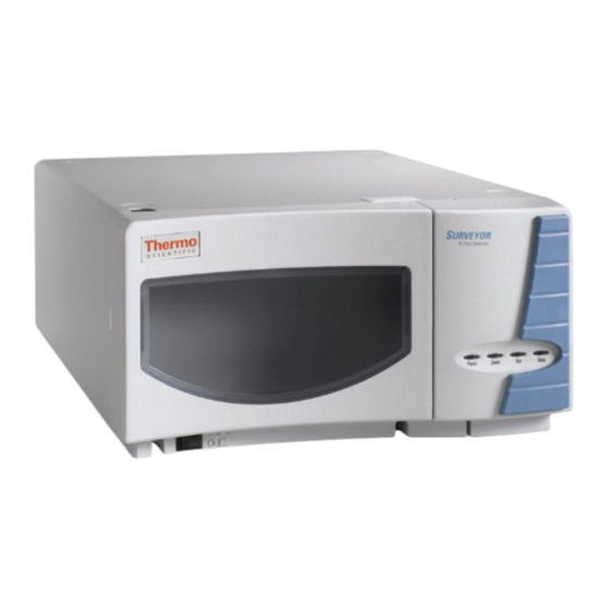
Introduction The Surveyor™ RI Plus Detector (see Figure 1) is a member of the Surveyor Plus family of LC instruments. This chapter provides an introduction to the Surveyor RI Plus Detector. Contents • Features • Front Panel • Back Panel •... -
Page 14: Features
Front Panel The front panel of the Surveyor RI Plus Detector provides access to the flowcell connections. Liquid enters the flowcell through the IN port and exits the flowcell through the OUT port. The accessory kit for the Surveyor RI Plus Detector contains the following tubing connections for the IN and OUT ports: •... -
Page 15: Back Panel
Terminal No. Label Description Ground terminal +5V@150mA READY Signal out Ready ZERO External Signal in (AutoZero) Ground terminal PURGE External Signal In (purge On) RECORDER + Recorder out RECORDER - Recorder out Thermo Scientific Surveyor RI Plus Detector Hardware Manual... -
Page 16: Status Leds
A run is in progress and the detector is sending data to the data system computer. Temp Amber The temperature of the detector is not equilibrated. Green The detector has reached a stable. Surveyor RI Plus Detector Hardware Manual Thermo Scientific... -
Page 17: Chromquest User Interface
ChromQuest User Interface ChromQuest User Interface You control the Surveyor RI Plus Detector, as well as the other modules of the Surveyor Plus LC system, from the ChromQuest chromatography data system. The ChromQuest user interface has two windows: Main Menu and Instrument. You administrate and configure the instrument in the Main Menu window. -
Page 18: Theory Of Operation
Flowcell Optical System The optical design of the Surveyor RI Plus Detector is based on Snell’s Law of Refraction, which uses a prism flowcell. The detector has a flowcell with two compartments that (the sample and reference) form a pair of liquid prisms. - Page 19 (item 1). This image passes through the collimator lens (item 4) and slit no.2 (item 5), which project the image of slit no. 2 through the flowcell (item 6) and onto the photodiode (item 9). Thermo Scientific Surveyor RI Plus Detector Hardware Manual...
-
Page 20: Flowcell
• When the Purge Control is On, solvent flows through both the sample and the reference compartments of the flowcell. • When the Purge Control is Off, the reference compartment of the flowcell is shut off from the solvent path. Surveyor RI Plus Detector Hardware Manual Thermo Scientific... - Page 21 To waste liquid valve receptacle 316 stainless tubing NC = Normally closed NO = Normally open 316 stainless tubing (closed) COM = Valve exit Teflon tubing Connection by female nut Connection by flange Thermo Scientific Surveyor RI Plus Detector Hardware Manual...
-
Page 22: Specifications
Introduction Specifications Specifications The Surveyor RI Plus Detector meets the following specifications. Method of detection: Deflection Refractive index range: 1.00 to 1.75 RIU Attenuator range: 0.25 to 512 μRIU Linearity range: 600 μRIU Noise: = 2.5 × 10 RIU (Response:1.5 seconds) Rise time: 0.1, 0.25, 0.5, 1, 2. -
Page 23: Installation
Installation This chapter describes the initial installation of your Surveyor RI Plus Detector, including connection to the other modules of the Surveyor Plus system. The Installation Checklist, on the back of this page, is an abbreviated version of this chapter and can be used as a quick reference of how to conduct a successful installation. -
Page 24: Installation Checklist
If any items are missing, contact your Thermo Fisher Scientific representative immediately. Note Before you install the software driver for the Surveyor RI Plus Detector, you must first install the ChromQuest chromatography data system. -
Page 25: Loosening The Transport Screws
Installation Loosening the Transport Screws Table 5. Surveyor RI Plus Detector accessory kit (60253-62000) Item Quantity Part Number Ethernet cable 70111-63302 Fittings, luer 00109-02-00014 Fittings, PEEK 2522-0285 Fuses, T3.15 AL250, 5 × 20mm 00006-02-00010 (for 115V operation) Fuses, T1.6 AL250, 5 × 20mm... -
Page 26: Integrating The Detector Into The Lc System
Place the detector on a bench top as close as possible to the chromatographic column outlet (minimizing the length of tubing necessary for connection to the flowcell inlet). If you are using other Surveyor Plus modules, place the Surveyor RI Plus Detector on top of the Surveyor Plus Autosampler as shown in... -
Page 27: Making The Initial Back Panel Connections
2. Connect the other end of the Ethernet cable to an Ethernet switch. Figure 10. Ethernet connections Solvent platform Ethernet port RI detector 8-pin receptacle for the interconnect cable Autosampler Computer ENET LC pump Ethernet box CAT5 shielded Ethernet cables Thermo Scientific Surveyor RI Plus Detector Hardware Manual... -
Page 28: Connecting The System Interconnect Cable
Figure 11. 5-connector version of the system interconnect cable MS Detector F5049-010 Detector Autosampler LC Pump MS Pump Figure 12. 7-connector version of the system interconnect cable MS Detector Detector Detector Detector Autosampler Pump Pump Surveyor RI Plus Detector Hardware Manual Thermo Scientific... - Page 29 Figure 13. Interconnect cable connections MS Detector Detector Detector Detector Solvent platform Autosampler Pump LC Pump Detector Interconnect cable (back panel) MS detector (unused) Autosampler (back panel) Surveyor LC Pump Plus (back panel) PUMP Thermo Scientific Surveyor RI Plus Detector Hardware Manual...
-
Page 30: Connecting The Inlet And Outlet Tubing
Figure 4. Connect the 0.060 in. ID × 1/16 in., Teflon™ outlet tubing to the OUT port. 5. Connect other end of the outlet tubing to a waste bottle. Surveyor RI Plus Detector Hardware Manual Thermo Scientific... - Page 31 Connecting the Inlet and Outlet Tubing Figure 14. Solvent line connections Wash In port RI detector (connection to LC column) Out port (connection to waste) 0.060 in. ID tubing Autosampler LC column LC pump DRAIN Thermo Scientific Surveyor RI Plus Detector Hardware Manual...
- Page 32 Figure 15. Connecting the inlet and outlet tubing to the RI detector Wash PDA detector 0.005 in. ID tubing Autosampler LC column RI Detector LC pump DRAIN 0.060 in. ID tubing To waste Surveyor RI Plus Detector Hardware Manual Thermo Scientific...
-
Page 33: Installing The Software Driver
The instrument control software for the Surveyor RI Plus Detector software is not installed with the ChromQuest data system. Before you install the instrument control software for the RI detector, you must first install the ChromQuest data system. Refer to the Surveyor RI Plus Detector CD jewel case for installation instructions. - Page 34 Installation Configuring the RI Detector in ChromQuest Figure 17. Surveyor dialog box 5. In the Configured modules pane, double-click the icon for the Surveyor RI Plus Detector. The Surveyor RI Plus Detector Configuration dialog box appears as shown in Figure Figure 18.
-
Page 35: Powering On The Detector For The First Time
35 °C. Chapter 5, “Troubleshooting,” for a complete description of LED status indications. Call your Thermo Fisher Scientific Service Representative if you require assistance. Thermo Scientific Surveyor RI Plus Detector Hardware Manual... -
Page 37: Operation
ChromQuest data system as described in the Surveyor Plus Getting Started with ChromQuest Guide. Contents • General Operating Instructions • Preparing for Routine Operation • Purging the Flowcell • Calibrating the Detector • Solvent Selection Thermo Scientific Surveyor RI Plus Detector Hardware Manual... -
Page 38: General Operating Instructions
1. Turn on the modules of the Surveyor Plus LC system. Note To avoid long warm-up periods, you can leave the detector in continuous operation. The typical lifespan of the tungsten lamp is 4.5 years during continuous operation. Surveyor RI Plus Detector Hardware Manual Thermo Scientific... - Page 39 11. Check the stability of the baseline: a. Choose Control > Instrument Status. b. Click the Surveyor RI Plus tab. c. Click the RI Status tab. d. Check that the value displayed in the Status readback is stable.
-
Page 40: Purging The Flowcell
3. Open the RI Status page: a. Choose Control > Instrument Status. The Instrument Status window appears. b. Click the Surveyor RI Plus tab. c. Click the RI Diagnostic tab. 4. In the Purge Control area, click On. The Purge status should display On. -
Page 41: Calibrating The Detector
Operation Calibrating the Detector Calibrating the Detector ChromQuest contains the following built-in calibration procedures for the Surveyor RI Plus Detector: Validation Procedure, Span Adjustment, Recorder Output Adjustment, Integrator Output Adjustment, and Intensity Adjustment. Perform the Validation Procedure, which validates the accuracy of the detector, on a regularly scheduled basis. - Page 42 8. Click Done when you have completed the adjustment. 9. Disconnect the multimeter from the pin connector adapter. 10. Disconnect the pin connector adapter from pins 9 and 10, located on the back of the detector. Surveyor RI Plus Detector Hardware Manual Thermo Scientific...
-
Page 43: Integrator Output Adjustment Procedure
8. Click Done when you have completed the adjustment. 9. Disconnect the multimeter from the pin connector adapter. 10. Disconnect the pin connector adapter from pins 13 and 14, located on the back of the detector. Thermo Scientific Surveyor RI Plus Detector Hardware Manual... -
Page 44: Solvent Selection
Solvents mixed and delivered by the pump will show compositional changes detectable by the refractive index detector even after passage through the chromatographic system. This effect can be minimized but not eliminated by adding additional mixing before the injector. Surveyor RI Plus Detector Hardware Manual Thermo Scientific... -
Page 45: Maintenance
This chapter describes the maintenance procedures that you must perform to ensure optimum performance of the Surveyor RI Plus Detector. The performance of your Surveyor RI Plus Detector depends on the proper maintenance of the flowcell and the wetted components in the LC system. -
Page 46: Recommendations For Routine Maintenance
Recommendations for Routine Maintenance Recommendations for Routine Maintenance Table 6 lists recommendations for routine maintenance of the Surveyor RI Plus Detector. Use this table as a basis for developing your maintenance program in accordance with the practices at your company. -
Page 47: Cleaning Detector External Surfaces
CAUTION Nitric acid is a strong oxidizing agent that reacts vigorously and violently with flammable organic solvents. To flush the flowcell 1. Connect the Surveyor LC Pump Plus directly to the Surveyor RI Plus Detector. 2. Launch ChromQuest. The online Instrument window appears. -
Page 48: Replacing The Fuses
Figure 22. Replacing the fuses Fuse holder Fuses Lever Fuse holder 6. Install the power cord on the back panel of the detector. 7. Press the power switch to power on the detector. Surveyor RI Plus Detector Hardware Manual Thermo Scientific... -
Page 49: Troubleshooting
Flush the flowcell with following mobile phase isopropanol, then with changeover. mobile phase. c. Electrical interference. c. Check the electrical lines for good connections and/or interference from broadcast radiation. Check for ground loops. Thermo Scientific Surveyor RI Plus Detector Hardware Manual... - Page 50 “Maintenance.” Integrator input voltage Verify that the integrator is does not match detector connected to the output voltage. appropriate Analog Output connections on the detector. Check the attenuation setting on the integrator. Surveyor RI Plus Detector Hardware Manual Thermo Scientific...
- Page 51 Increase the flow rate until flowcell. the bubble is removed. Connect a backpressure device to the flowcell outlet (check backpressure rating to avoid rupturing flowcell). Large temperature Remove system from drafts. fluctuations. Thermostatically control column temperature. Thermo Scientific Surveyor RI Plus Detector Hardware Manual...
- Page 52 Run contacts on the injection. back panel. 8. LED1 - Power a. Green - power On. a. No action is required. b. Off - no power. b. Check the fuse, line voltage, and so on. Surveyor RI Plus Detector Hardware Manual Thermo Scientific...
-
Page 53: Error Messages
Error messages appear in pop-ups or in the RI Status page. These possible error messages include, but are not limited to, those listed in Table 8 Table 9. If the symptom persist, call your Thermo Fisher Scientific service representative for assistance. Thermo Scientific Surveyor RI Plus Detector Hardware Manual... - Page 54 Light intensity too low Purge the detector. Flush the flowcell with fresh mobile phase. Instrument connection loss Check Ethernet connection and start the software. Check the module configuration in the software. Extend Run failed. Surveyor RI Plus Detector Hardware Manual Thermo Scientific...
-
Page 55: Chapter A Accessories And Replaceable Parts
Accessories and Replaceable Parts This chapter lists of accessories and replaceable parts for the Surveyor RI Plus Detector that you can order from Thermo Fisher Scientific. Ethernet cable ..........70111-63302 Interconnect cable, 7- connector . -
Page 57: Index
Communications Flushing flowcell cable connections Fuses LEDs replacing Configuring detector thermal fuse Connecting cables Connections back panel flowcell Gases, dissolved tubing Ground loop problems, causes of Contamination from samples Thermo Scientific Surveyor RI Plus Detector Hardware Manual... - Page 58 Unpacking your detector theory of unpacking Validation of accuracy Parts, replaceable Peak problems Photodiode, movement of image on Ports connecting in and out Ethernet Positioning the detector Power on detector Surveyor RI Plus Detector Hardware Manual Thermo Scientific...
Need help?
Do you have a question about the Surveyor RI Plus and is the answer not in the manual?
Questions and answers