
Subscribe to Our Youtube Channel
Related Manuals for WAGO WAGO-TO-PASS 761


Summary of Contents for WAGO WAGO-TO-PASS 761
- Page 1 Manual WAGO-TO-PASS® 761 Telecontrol Module Compact, 8 AI, Web, MODBUS485 761-217 Telecontrol module for fault detection/indication, monitoring and remote control Version 1.0.0...
- Page 2 WAGO-TO-PASS® 761 761-217 Telecontrol Module Compact, 8 AI, Web, MODBUS485 © 2013 by WAGO Kontakttechnik GmbH & Co. KG All rights reserved. WAGO Kontakttechnik GmbH & Co. KG Hansastraße 27 D-32423 Minden Phone: +49 (0) 571/8 87 – 0 Fax: +49 (0) 571/8 87 –...
-
Page 3: Table Of Contents
Shielding ..................... 22 3.4.4.1 General ................... 22 3.4.4.2 Bus Lines ..................22 3.4.4.3 Signal Lines ................... 22 3.4.4.4 WAGO Shield Connecting System ..........23 3.4.5 Digital Inputs ..................24 3.4.6 Counter Inputs ..................25 3.4.7 Analog Inputs ..................26 3.4.8 Digital Outputs ................... - Page 4 Table of Contents WAGO-TO-PASS® 761 761-217 Telecontrol Module Compact, 8 AI, Web, MODBUS485 3.6.5 MODBUS Communication ..............35 3.6.6 Digital Inputs ..................35 3.6.7 Counter Inputs ..................35 3.6.8 Analog Inputs ..................36 3.6.9 Digital Outputs ................... 36 3.6.10 Analog Outputs ................... 36 3.6.11...
-
Page 5: Table Of Contents
WAGO-TO-PASS® 761 Table of Contents 761-217 Telecontrol Module Compact, 8 AI, Web, MODBUS485 Transmission Repeat Times ..............77 Time Adjustment ..................80 MODBUS ....................81 7.9.1 MODBUS Settings ................82 7.9.2 MODBUS Alarm ................83 7.9.3 MODBUS Registers ................84 7.10... - Page 6 Table of Contents WAGO-TO-PASS® 761 761-217 Telecontrol Module Compact, 8 AI, Web, MODBUS485 10.3.2.2 Logger Script Extension .............. 124 10.3.2.2.1 Data Format for LIOx Variable ..........125 10.3.2.2.2 Data Format for LPDx Variable ..........125 10.3.2.2.3 Example for Logger Script Extension ........126 10.3.2.3...
-
Page 7: Notes About This Documentation
Manual by third parties that violate pertinent copyright provisions is prohibited. Reproduction, translation, electronic and phototechnical filing/archiving (e.g., photocopying) as well as any amendments require the written consent of WAGO Kontakttechnik GmbH & Co. KG, Minden, Germany. Non-observance will involve the right to assert damage claims. Manual... -
Page 8: Symbols
Notes about this Documentation WAGO-TO-PASS® 761 761-217 Telecontrol Module Compact, 8 AI, Web, MODBUS485 Symbols Personal Injury! Indicates a high-risk, imminently hazardous situation which, if not avoided, will result in death or serious injury. Personal Injury Caused by Electric Current! Indicates a high-risk, imminently hazardous situation which, if not avoided, will result in death or serious injury. - Page 9 WAGO-TO-PASS® 761 Notes about this Documentation 761-217 Telecontrol Module Compact, 8 AI, Web, MODBUS485 Additional Information: Refers to additional information which is not an integral part of this documentation (e.g., the Internet). Manual Version 1.0.0...
-
Page 10: Number Notation
Notes about this Documentation WAGO-TO-PASS® 761 761-217 Telecontrol Module Compact, 8 AI, Web, MODBUS485 Number Notation Table 1: Number notation Number code Example Note Decimal Normal notation Hexadecimal 0x64 C notation Binary '100' In quotation marks, nibble separated with '0110.0100' dots (.) -
Page 11: Important Notes
2.1.1 Subject to Changes WAGO Kontakttechnik GmbH & Co. KG reserves the right to provide for any alterations or modifications that serve to increase the efficiency of technical progress. WAGO Kontakttechnik GmbH & Co. KG owns all rights arising from the granting of patents or from the legal protection of utility patents. -
Page 12: Disclaimer
GPL. According to Section 3b of GPL, we offer you the source code. You can obtain the source code with licensing terms of the Open Source software from WAGO Kontakttechnik GmbH & Co. KG on request. Send your request to support@wago.com with the subject "Open Source TO-PASS Compact". -
Page 13: Safety Advice (Precautions)
WAGO-TO-PASS® 761 Important Notes 761-217 Telecontrol Module Compact, 8 AI, Web, MODBUS485 Safety Advice (Precautions) For installing and operating purposes of the relevant device to your system the following safety precautions shall be observed: Do not work on components while energized! All power sources to the device shall be switched off prior to performing any installation, repair or maintenance work. - Page 14 Important Notes WAGO-TO-PASS® 761 761-217 Telecontrol Module Compact, 8 AI, Web, MODBUS485 Please note the following information about FCC Part 15! FCC Part 15.19 This device complies with Part 15 of the FCC Rules. Operation is subject to the following conditions: 1.
- Page 15 WAGO-TO-PASS® 761 Important Notes 761-217 Telecontrol Module Compact, 8 AI, Web, MODBUS485 Protect the components against materials having seeping and insulating properties! The components are not resistant to materials having seeping and insulating properties such as: aerosols, silicones and triglycerides (found in some hand creams).
-
Page 16: Device Description
Please note that one SIM card is required to operate each TO-PASS telecontrol module and may be obtained from typical service providers such as T-Mobile, VODAFONE or EPlus. WAGO Kontakttechnik GmbH & Co. K.G. is prepared to assist with the selection of the most cost-effective tariff for your application. ®... -
Page 17: Table 3: Overview Of Functions
WAGO-TO-PASS® 761 Device Description 761-217 Telecontrol Module Compact, 8 AI, Web, MODBUS485 Table 3: Overview of functions Functionality FW 2.20 FW 2.31 FW 2.32 FW 2.33 Module name length 8 characters*) 16 characters*) 16 characters*) 16 characters*) (Identity) “Prepaid” request... -
Page 18: View
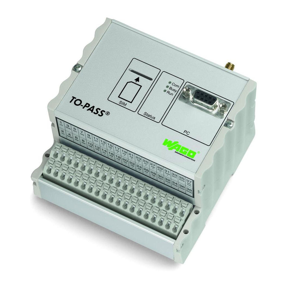
Device Description WAGO-TO-PASS® 761 761-217 Telecontrol Module Compact, 8 AI, Web, MODBUS485 View Figure 1: Front view Position Description SIM Card insert Antenna connection Statusindication PC interface Connecting terminals for the supply, inputs and outputs Manual Version 1.0.0... -
Page 19: Connectors
WAGO-TO-PASS® 761 Device Description 761-217 Telecontrol Module Compact, 8 AI, Web, MODBUS485 Connectors 3.4.1 Antenna The screw connector (SMA socket) for the GSM antenna is located at the top of the housing. Figure 2: Antenna connection Observe the maximum length of the antenna cable! -
Page 20: Operating Voltage
Device Description WAGO-TO-PASS® 761 761-217 Telecontrol Module Compact, 8 AI, Web, MODBUS485 3.4.2 Operating Voltage Use SELV/PELV power source only! ® The TO-PASS telecontrol module must only be powered from a PELV (Protective Extra Low Voltage) or SELV (Safety Extra Low Voltage) power source complying with the limited power source (LPS) requirements per DIN EN 60950-1. -
Page 21: Grounding
The separate grounding of the carrier rail can be easily set up with the aid of the WAGO ground wire terminals. Table 5: WAGO ground wire terminals Item No. Description 283-609 1-conductor ground (earth) terminal block make an automatic contact to the carrier rail;... -
Page 22: Shielding
Higher shielding performance is achieved via low-impedance connection between shield and ground. To achieve this, connect the shield over a large surface area, e.g., WAGO shield connecting system. This is especially recommended for large- scale systems where equalizing current or high impulse-type currents caused by atmospheric discharge may occur. -
Page 23: Wago Shield Connecting System
3.4.4.4 WAGO Shield Connecting System The WAGO shield connecting system consists of shield clamping saddles, busbars and various mounting carriers to enable a wide variety of setups. For more information on this, refer to the "Accessories" section of the main catalog. -
Page 24: Digital Inputs
Device Description WAGO-TO-PASS® 761 761-217 Telecontrol Module Compact, 8 AI, Web, MODBUS485 3.4.5 Digital Inputs Only connect SELV/PELV voltages! Only SELV/PELV voltages shall be connected to the device terminals. Table 6: Terminal assignment for digital inputs Figure 5: Terminal assignment for digital inputs... -
Page 25: Counter Inputs
WAGO-TO-PASS® 761 Device Description 761-217 Telecontrol Module Compact, 8 AI, Web, MODBUS485 3.4.6 Counter Inputs Only connect SELV/PELV voltages! Only SELV/PELV voltages shall be connected to the device terminals. Digital inputs D1 … D4 can be configured as counter inputs. -
Page 26: Analog Inputs
Device Description WAGO-TO-PASS® 761 761-217 Telecontrol Module Compact, 8 AI, Web, MODBUS485 3.4.7 Analog Inputs Only connect SELV/PELV voltages! Only SELV/PELV voltages shall be connected to the device terminals. Table 8: Terminal assignment for analog inputs Figure 7: Terminal assignment for analog inputs... - Page 27 WAGO-TO-PASS® 761 Device Description 761-217 Telecontrol Module Compact, 8 AI, Web, MODBUS485 Analog inputs are single-ended! The analog inputs are single-ended and the “Aix–” connections are connected internally to the “GND” connections. Connect shielding! Shielded cables are required for analog inputs. The cable shield must be connected to the grounded DIN rail (see section "Connections"...
-
Page 28: Digital Outputs
Device Description WAGO-TO-PASS® 761 761-217 Telecontrol Module Compact, 8 AI, Web, MODBUS485 3.4.8 Digital Outputs Only connect SELV/PELV voltages! Only SELV/PELV voltages shall be connected to the device terminals. Table 9: Terminal assignment for digital outputs Figure 8: Terminal assignment for digital outputs... -
Page 29: Analog Outputs
WAGO-TO-PASS® 761 Device Description 761-217 Telecontrol Module Compact, 8 AI, Web, MODBUS485 3.4.9 Analog Outputs Only connect SELV/PELV voltages! Only SELV/PELV voltages shall be connected to the device terminals. Table 10: Terminal assignment for analog outputs Figure 9: Terminal assignment for analog outputs... -
Page 30: Serial Interface To The Pc And Modbus Interface
Device Description WAGO-TO-PASS® 761 761-217 Telecontrol Module Compact, 8 AI, Web, MODBUS485 3.4.10 Serial Interface to the PC and MODBUS Interface Table 11: Serial interface to the PC and MODBUS interface Description Not assigned Not assigned Not assigned MODBUS D1 (B) -
Page 31: Figure 11: Modbus Communication Diagram
WAGO-TO-PASS® 761 Device Description 761-217 Telecontrol Module Compact, 8 AI, Web, MODBUS485 Table 13: MODBUS cable assignment ® TO-PASS MODBUS Telecontrol Module Communication Partner Description Description MODBUS GND MODBUS D1 (B) MODBUS D1 (B) MODBUS D0 (A) MODBUS D0 (A) - Page 32 Device Description WAGO-TO-PASS® 761 761-217 Telecontrol Module Compact, 8 AI, Web, MODBUS485 Connect shielding! Shielded cables are required for MODBUS communication. The cable shield must be connected to the DIN rail (see section "Connections" > "Shielding"). Manual Version 1.0.0...
-
Page 33: Display Elements
WAGO-TO-PASS® 761 Device Description 761-217 Telecontrol Module Compact, 8 AI, Web, MODBUS485 Display Elements Table 14: Display Elements Busy Description Green 0.5 Hz Ready to operate blinking Communication via RS232 Green interface Green 1 Hz Firmware update blinking GSM modem is activated Initialization (takes approx. -
Page 34: Technical Data
-40 °C ... +85 °C Type of mounting DIN 35 rail Degree of protection IP 20 Wire connection Terminal strips (WAGO 250 Series) with push-wire connection Cross section 0,5 mm² … 1,0 mm² AWG 22 … AWG 14 „sol“ Stripped length 9 mm …... -
Page 35: Gsm Communication
WAGO-TO-PASS® 761 Device Description 761-217 Telecontrol Module Compact, 8 AI, Web, MODBUS485 3.6.4 GSM Communication Table 18: Technical Data Communication Number of recipients Recipient types PC, SMS, e-mail, phone, fax Communication GSM quad-band Communication types SMS (bidirectional), telecommunication dial-up connection... -
Page 36: Analog Inputs
Device Description WAGO-TO-PASS® 761 761-217 Telecontrol Module Compact, 8 AI, Web, MODBUS485 3.6.8 Analog Inputs Table 22: Technical Data Analog Inputs Number of inputs Input current 0/4 mA ... 20 mA Approx.. 200 Ω / 20 mA Internal resistance Resolution 12 bit Measuring error (25°C) -
Page 37: Approvals
WAGO-TO-PASS® 761 Device Description 761-217 Telecontrol Module Compact, 8 AI, Web, MODBUS485 Approvals The following approvals have been granted to 761-217 telecontrol modules: Conformity Marking UL508 R&TTE Complaint with 1999/5/EG directive (per Article 3.2) RoHS Device complies with European RoHS directive. -
Page 38: Mounting
IP20 degree of protection ® The protection class of the TO-PASS telecontrol module is IP 20. For this reason, WAGO Kontakttechnik GmbH & Co. KG recommends mounting in a housing or in a switching cabinet. Ambient temperature -20 °C to +70 °C ®... -
Page 39: Removing The To-Pass ® Telecontrol Module From The Din Rail
WAGO-TO-PASS® 761 Mounting 761-217 Telecontrol Module Compact, 8 AI, Web, MODBUS485 ® Removing the TO-PASS telecontrol module from the DIN rail ® Figure 14: Removing the TO-PASS telecontrol module from the DIN rail ® Press the undersurface against the lower DIN rail edge until the TO-PASS telecontrol module is no longer locked in place. -
Page 40: Connect Devices
If more than one conductor must be routed to one connection, these must be connected in an up-circuit wiring assembly, for example using WAGO feed- through terminals. Terminate both solid and ferruled conductors without actuation by simply pushing them in. -
Page 41: Connection Examples
WAGO-TO-PASS® 761 Connect Devices 761-217 Telecontrol Module Compact, 8 AI, Web, MODBUS485 Connection Examples Connect the shield connection to the DIN rail! ® The shield connection of the TO-PASS telecontrol module (shield, terminal 38) must be connected to the DIN rail. The DIN rail must have a low-impedance ground (see section "Connections"... -
Page 42: Counter Inputs
Connect Devices WAGO-TO-PASS® 761 761-217 Telecontrol Module Compact, 8 AI, Web, MODBUS485 5.2.2 Counter Inputs Only connect SELV/PELV voltages! Only SELV/PELV voltages shall be connected to the device terminals. Connect shielding! Shielded cables are recommended for the counter inputs. When using shielded cables, the shield must be routed to the grounded DIN rail (see Section "Connections"... -
Page 43: Analog Inputs
WAGO-TO-PASS® 761 Connect Devices 761-217 Telecontrol Module Compact, 8 AI, Web, MODBUS485 5.2.3 Analog Inputs Only connect SELV/PELV voltages! Only SELV/PELV voltages shall be connected to the device terminals. Analog inputs are single-ended! The analog inputs are single-ended and the “Aix–” connections are connected internally to the “GND”... -
Page 44: Voltage Measurement
® since the internal resistance of the TO-PASS telecontrol module depends on the input current. WAGO 857 Series JUMPFLEX Isolation Amplifiers for level conversion may be ® used for voltage measurement via TO-PASS telecontrol modules. Figure 18: Connection example for voltage measurement via U/I converter at input AI1 Manual Version 1.0.0... -
Page 45: Digital Outputs
WAGO-TO-PASS® 761 Connect Devices 761-217 Telecontrol Module Compact, 8 AI, Web, MODBUS485 5.2.4 Digital Outputs Only connect SELV/PELV voltages! Only SELV/PELV voltages shall be connected to the device terminals. Figure 19: Connection example for a relay at DO1 output Manual... -
Page 46: Analog Outputs
Connect Devices WAGO-TO-PASS® 761 761-217 Telecontrol Module Compact, 8 AI, Web, MODBUS485 5.2.5 Analog Outputs Only connect SELV/PELV voltages! Only SELV/PELV voltages shall be connected to the device terminals. Connect shielding! Shielded cables are required for analog outputs. The cable shield must be connected to the grounded DIN rail (see section "Connections"... -
Page 47: Voltage Measurement
WAGO-TO-PASS® 761 Connect Devices 761-217 Telecontrol Module Compact, 8 AI, Web, MODBUS485 5.2.5.2 Voltage Measurement : Load resistance, R : Internal resistance of measuring device must be less than 600 Ω. || R With R >> R the impact of R can be neglected. -
Page 48: Modbus Interface
Connect Devices WAGO-TO-PASS® 761 761-217 Telecontrol Module Compact, 8 AI, Web, MODBUS485 5.2.6 MODBUS Interface MODBUS Line terminator The MODBUS specification requires a line terminator at both ends of an RS-485 bus. ® If the TO-PASS telecontrol module is operated at one end of the line, the terminator must be added (e.g., directly in the D-Sub plug-in connector, or at the... -
Page 49: Modbus Coupler/Controller Rs-485
WAGO-TO-PASS® 761 Connect Devices 761-217 Telecontrol Module Compact, 8 AI, Web, MODBUS485 5.2.6.1 MODBUS Coupler/Controller RS-485 Figure 21: Connection example for MODBUS Coupler/Controller RS-485 Manual Version 1.0.0... -
Page 50: Serial Interface For Modbus Current Sensor And Pc
Connect Devices WAGO-TO-PASS® 761 761-217 Telecontrol Module Compact, 8 AI, Web, MODBUS485 5.2.6.2 Serial Interface for MODBUS Current Sensor and PC Figure 22: Connection example for serial interface for MODBUS current sensor and PC Manual Version 1.0.0... -
Page 51: Commissioning
Select the CD drive in which you have placed the CD with the operating software. Start the "WAGO TO-PASS_SETUP(2.17).EXE" program, or a newer version in the main directory on the CD. Follow the menu prompting to choose a default installation path. -
Page 52: Starting The To-Pass Telecontrol Module
Commissioning WAGO-TO-PASS® 761 761-217 Telecontrol Module Compact, 8 AI, Web, MODBUS485 ® Starting the TO-PASS Telecontrol Module Do not switch on yet! ® Do not switch on the TO-PASS telecontrol module until you are prompted to do so; do not insert the SIM card for this procedure. - Page 53 WAGO-TO-PASS® 761 Commissioning 761-217 Telecontrol Module Compact, 8 AI, Web, MODBUS485 When generating a new configuration file, select the firmware version for the device that implements the required functionality as the first version in the Function selection field. The device versions, along with the associated enabling firmware indices are displayed to make selection easier.
-
Page 54: Parameterizing
Parameterizing WAGO-TO-PASS® 761 761-217 Telecontrol Module Compact, 8 AI, Web, MODBUS485 Parameterizing General Settings Select the menu item File Settings for making general settings, such as type of > ® connection, interface or language for the TO-PASS operating interface. Figure 23: General settings... - Page 55 WAGO-TO-PASS® 761 Parameterizing 761-217 Telecontrol Module Compact, 8 AI, Web, MODBUS485 Table 26: General settings Interface COM1 ... COMx Here, select the serial interface where the communication cable is connected with a RS-232 connection. Language ® English / Select the langauge for the TO-PASS operator interface here.
-
Page 56: Reading Parameters From The Module
Parameterizing WAGO-TO-PASS® 761 761-217 Telecontrol Module Compact, 8 AI, Web, MODBUS485 Reading Parameters from the Module ® After you have set the type of connection for communicating with the TO-PASS telecontrol module, you are then able to read out the parameters of the connected module. -
Page 57: Identity
WAGO-TO-PASS® 761 Parameterizing 761-217 Telecontrol Module Compact, 8 AI, Web, MODBUS485 Identity ® Select the TO-PASS telecontrol module to be configured from the project tree; under it, select the Identity option. On the right side you will find the selection field for the function, the display field for the name, the input field for the telephone number, buttons and input fields for the PIN, roaming and prepaid and the input field for the alarm counter. -
Page 58: Table 27: Configuring The Identity
Parameterizing WAGO-TO-PASS® 761 761-217 Telecontrol Module Compact, 8 AI, Web, MODBUS485 Table 27: Configuring the identity General Function selection You can redifine the firmware version in this selection field, that is to say the available scope of functions (e.g., to ensure compatibility with devices already in use). -
Page 59: Addresses
WAGO-TO-PASS® 761 Parameterizing 761-217 Telecontrol Module Compact, 8 AI, Web, MODBUS485 Addresses ® The TO-PASS telecontrol module can communicate with a maximum of four ® transmitters/receivers via GSM. Messages are sent by the TO-PASS telecontrol module as SMS; however, they can also be sent as an e-mail, fax or voice mail, as defined in configuration. -
Page 60: Table 28: Configuring The Addresses
Parameterizing WAGO-TO-PASS® 761 761-217 Telecontrol Module Compact, 8 AI, Web, MODBUS485 Table 28: Configuring the addresses Phone/Fax/Mail Address 1 ... Enter the target addresses in these fields: Address 4 Transmission as SMS: Enter the mobile phone number of the recipient. - Page 61 In this field enter the port for the Web portal (e.g., "80" for most http applications) Script (value), In this field enter the script name for data transmission, for for transmitting test purposes, e.g., "wago/saveTO-PASS.php". alarms and status The "saveTO-PASS.php" script checks the version messages indications from transmitted data and forwards this information to the processing script.
-
Page 62: Configuring Inputs And Outputs
Parameterizing WAGO-TO-PASS® 761 761-217 Telecontrol Module Compact, 8 AI, Web, MODBUS485 Configuring Inputs and Outputs 7.5.1 Digital Inputs ® Select your TO-PASS telecontrol module from the left side of the project tree using the identifier. Select the input to be configured under Digital Inputs. -
Page 63: Figure 27: Configuring Digital Inputs 5
WAGO-TO-PASS® 761 Parameterizing 761-217 Telecontrol Module Compact, 8 AI, Web, MODBUS485 Figure 27: Configuring digital inputs 5 … 8 (when provided) Table 29: Configuring of digital inputs Counters (only for digital inputs 1 … 4) Counters Check this box to use the selected digital input as a counter input. - Page 64 Parameterizing WAGO-TO-PASS® 761 761-217 Telecontrol Module Compact, 8 AI, Web, MODBUS485 Table 29: Configuring of digital inputs Alarm settings First value Check this box to have a message sent when the first limit is exceeded for upward counting or when the first lower limit is violated for downward counting.
- Page 65 WAGO-TO-PASS® 761 Parameterizing 761-217 Telecontrol Module Compact, 8 AI, Web, MODBUS485 Table 29: Configuring of digital inputs Deactivation text In this field enter the text to be contained in the message transmitted when the digital input has been reset, or when the counted value has violated the second limit.
-
Page 66: Multiplex Input
Parameterizing WAGO-TO-PASS® 761 761-217 Telecontrol Module Compact, 8 AI, Web, MODBUS485 7.5.2 Multiplex Input You can configure digital inputs DI1 ... DI4 as multiplex inputs. These four inputs will then additionally be read in as a combination and intepreted as a binary number. -
Page 67: Multiplex Settings
WAGO-TO-PASS® 761 Parameterizing 761-217 Telecontrol Module Compact, 8 AI, Web, MODBUS485 7.5.2.1 Multiplex Settings ® Select your TO-PASS telecontrol module from the left side of the project tree using the identifier. Select the Multiplex Settings option under Multiplex Input. The buttons for enabling multiplex operation and the selection of the recipients of the analog values to be transmitted are provided on the right side. -
Page 68: Multiplex Alarm Text
Parameterizing WAGO-TO-PASS® 761 761-217 Telecontrol Module Compact, 8 AI, Web, MODBUS485 7.5.2.2 Multiplex Alarm Text ® Select your TO-PASS telecontrol module from the left side of the project tree using the identifier. Select the Multiplex Table option under the Multiplex Input entry. -
Page 69: Analog Inputs
WAGO-TO-PASS® 761 Parameterizing 761-217 Telecontrol Module Compact, 8 AI, Web, MODBUS485 7.5.3 Analog Inputs ® Select your TO-PASS telecontrol module from the left side of the project tree using the identifier. Select the input to be configured under Analog Inputs. The parameters of the input are given on the right side. - Page 70 Parameterizing WAGO-TO-PASS® 761 761-217 Telecontrol Module Compact, 8 AI, Web, MODBUS485 Table 32: Configuring the analog inputs Alarm settings First value In this field enter the first limit for which a message is to be sent when this limit is violated (upper/lower limit) (see below).
-
Page 71: Digital Outputs
WAGO-TO-PASS® 761 Parameterizing 761-217 Telecontrol Module Compact, 8 AI, Web, MODBUS485 7.5.4 Digital Outputs ® Select your TO-PASS telecontrol module from the left side of the project tree using the identifier. Select the output to be configured under the entry Digital Outputs. -
Page 72: Analog Outputs
Parameterizing WAGO-TO-PASS® 761 761-217 Telecontrol Module Compact, 8 AI, Web, MODBUS485 7.5.5 Analog Outputs ® Select your TO-PASS telecontrol module from the left side of the project tree using the identifier. Select the output to be configured under Analog Outputs. - Page 73 WAGO-TO-PASS® 761 Parameterizing 761-217 Telecontrol Module Compact, 8 AI, Web, MODBUS485 Evaluation of places after the decimal point Starting with Firmware 02.33.08, places after the decimal point are also taken into account for switching of the analog outputs. A period (decimal point) "." must be used as the separator.
-
Page 74: Configuring Error Detectors
Parameterizing WAGO-TO-PASS® 761 761-217 Telecontrol Module Compact, 8 AI, Web, MODBUS485 Configuring Error Detectors ® The TO-PASS telecontrol module can transmit error messages to a maximum of four recipients. The recipients are informed either directly one after another or (if configured) after expiration of the time delay for acknowledgment. - Page 75 WAGO-TO-PASS® 761 Parameterizing 761-217 Telecontrol Module Compact, 8 AI, Web, MODBUS485 [4]. Click the [Internet] button to also transmit the message to a Web portal. In addition, you can also specify the analog values that are to be transmitted along with the error message.
-
Page 76: Acknowledgement
Parameterizing WAGO-TO-PASS® 761 761-217 Telecontrol Module Compact, 8 AI, Web, MODBUS485 7.6.4 Acknowledgement Acknowledgment is the confirmation that a message has actually been sent to the ® recipient. Select the TO-PASS telecontrol module from the project tree using the identifier. Select the entry Acknowledgment under the option Special Functions. -
Page 77: Transmission Repeat Times
WAGO-TO-PASS® 761 Parameterizing 761-217 Telecontrol Module Compact, 8 AI, Web, MODBUS485 Transmission Repeat Times ® Select the TO-PASS telecontrol module from the project tree using the identifier. Select the entry Repeat times under the option Special Functions. The input fields for the Web interval, the Web outputs and the SMS interval and buttons for target addresses are located on the right side. -
Page 78: Table 36: Configuring The Transmission Repeat Times
Parameterizing WAGO-TO-PASS® 761 761-217 Telecontrol Module Compact, 8 AI, Web, MODBUS485 Table 36: Configuring the transmission repeat times Web settings Web interval In this field enter the cycle time in minutes to define the ® intervals that the TO-PASS telecontrol module is to send data to the Internet. - Page 79 WAGO-TO-PASS® 761 Parameterizing 761-217 Telecontrol Module Compact, 8 AI, Web, MODBUS485 Table 36: Configuring the transmission repeat times SMS Settings SMS interval Here, enter the cycle time in minutes to define the intervals ® that the TO-PASS telecontrol module is to send data to the addresses defined under Address.
-
Page 80: Time Adjustment
Parameterizing WAGO-TO-PASS® 761 761-217 Telecontrol Module Compact, 8 AI, Web, MODBUS485 Time Adjustment ® Select the TO-PASS telecontrol module from the project tree using the identifier. Select the entry Acknowledgment under the option Time setting. The buttons for various settings pertaining to time adjustment are located on the right side. -
Page 81: Modbus
WAGO-TO-PASS® 761 Parameterizing 761-217 Telecontrol Module Compact, 8 AI, Web, MODBUS485 MODBUS The MODBUS functionality facilitates connectivity for MODBUS interface- equipped devices. The devices must be configured as slave devices and are ® connected via PC interface. As a result, the TO-PASS telecontrol module operates as a master. -
Page 82: Modbus Settings
Parameterizing WAGO-TO-PASS® 761 761-217 Telecontrol Module Compact, 8 AI, Web, MODBUS485 7.9.1 MODBUS Settings ® Select the TO-PASS telecontrol module from the project tree using the identifier. Select the MODBUS Settings option under the MODBUS entry. The buttons for the MODBUS format and the input field for the polling cycle time... -
Page 83: Modbus Alarm
WAGO-TO-PASS® 761 Parameterizing 761-217 Telecontrol Module Compact, 8 AI, Web, MODBUS485 7.9.2 MODBUS Alarm When using the MODBUS functionality, an input of a MODBUS device can be defined that triggers an alarm when it assumes the high state (logical "1"). -
Page 84: Modbus Registers
Parameterizing WAGO-TO-PASS® 761 761-217 Telecontrol Module Compact, 8 AI, Web, MODBUS485 7.9.3 MODBUS Registers A maximum of 64 registers can be read from the connected MODBUS subscribers. The registers are compiled in four groups (1 ... 16, 17 ... 32, 33 ... 48, 49 ... -
Page 85: Data Logger
WAGO-TO-PASS® 761 Parameterizing 761-217 Telecontrol Module Compact, 8 AI, Web, MODBUS485 7.10 Data Logger ® Select the TO-PASS telecontrol module from the project tree using the identifier. Select the entry Data Logger under the option Special Functions. The input field for the cycle time and a button for calculating the average value are located on the right side. -
Page 86: Writing Parameters To The Module
Parameterizing WAGO-TO-PASS® 761 761-217 Telecontrol Module Compact, 8 AI, Web, MODBUS485 7.11 Writing Parameters to the Module ® After you have adapted all parameters for the TO-PASS telecontrol module to your requirements, you have to write the parameters to the connected module. -
Page 87: Operation
WAGO-TO-PASS® 761 Operation 761-217 Telecontrol Module Compact, 8 AI, Web, MODBUS485 Operation Remote Query of Process Values ® The TO-PASS telecontrol module offers two options for remote inquiry of the process values available: • Query via SMS ® • Query with the TO-PASS... -
Page 88: Remote Polling Via Sms
Operation WAGO-TO-PASS® 761 761-217 Telecontrol Module Compact, 8 AI, Web, MODBUS485 8.1.1 Remote Polling via SMS For remote polling via SMS, send an SMS containing the text "State" to the TO- ® PASS telecontrol module. ® The TO-PASS telecontrol module responds promptly with an SMS to your mobile phone containing all of the current process values. -
Page 89: Table 44: Counter Status
WAGO-TO-PASS® 761 Operation 761-217 Telecontrol Module Compact, 8 AI, Web, MODBUS485 The counter status may be one of the following statuses: Table 44: Counter status Status Explanation Digital input not configured as a counter. e:ZW Counter is active: Counter value. -
Page 90: Remote Polling Using The To-Pass
Operation WAGO-TO-PASS® 761 761-217 Telecontrol Module Compact, 8 AI, Web, MODBUS485 ® 8.1.2 Remote Polling using the TO-PASS Operating Program ® To display the process values with the TO-PASS operator program, select the menu item Visualization > Process values. The program establishes a link to the ®... -
Page 91: Inputs/Outputs
WAGO-TO-PASS® 761 Operation 761-217 Telecontrol Module Compact, 8 AI, Web, MODBUS485 8.1.2.1 Inputs/Outputs Press the [I/O] button to display the process values of the inputs and outputs. The process values displayed are valid if the on-line display is green. Figure 40: Visualization of the process values... -
Page 92: Modbus
Operation WAGO-TO-PASS® 761 761-217 Telecontrol Module Compact, 8 AI, Web, MODBUS485 8.1.2.2 MODBUS Press the [MODBUS] button to display the MODBUS process values. The process values displayed are valid if the on-line display is green. Figure 41: MODBUS process values... -
Page 93: Counters
WAGO-TO-PASS® 761 Operation 761-217 Telecontrol Module Compact, 8 AI, Web, MODBUS485 8.1.2.3 Counters To display the counter process values, click the [Counter] button (possible only when inputs have been configured as counters). The process values displayed are valid when the on-line indicator is highlighted in green. -
Page 94: Telecontrol
Operation WAGO-TO-PASS® 761 761-217 Telecontrol Module Compact, 8 AI, Web, MODBUS485 Telecontrol ® TO-PASS telecontrol modules offer the option of influencing a process remotely with the help of their analog and digital outputs. There are two methods available: • Telecontrol via SMS ®... -
Page 95: Telecontrol Via Sms
WAGO-TO-PASS® 761 Operation 761-217 Telecontrol Module Compact, 8 AI, Web, MODBUS485 8.2.1 Telecontrol via SMS 8.2.1.1 Setting or Resetting a Digital Output To set or reset a digital output, send an SMS with the text that is entered under ®... -
Page 96: Setting An Analog Output
Operation WAGO-TO-PASS® 761 761-217 Telecontrol Module Compact, 8 AI, Web, MODBUS485 8.2.1.2 Setting an Analog Output To set an analog output, send an SMS with the text, which is entered under Set ® output, and the value to be set to the TO-PASS telecontrol module. -
Page 97: Changing The Counter Value Or Status
WAGO-TO-PASS® 761 Operation 761-217 Telecontrol Module Compact, 8 AI, Web, MODBUS485 8.2.1.3 Changing the Counter Value or Status To change the value or the status of a counter, send an SMS containing the text "Counter" and the corresponding control commands (more than one can be sent) ®... -
Page 98: Telecontrol With The To-Pass
Operation WAGO-TO-PASS® 761 761-217 Telecontrol Module Compact, 8 AI, Web, MODBUS485 ® 8.2.2 Telecontrol with the TO-PASS Operator Program ® To display the process values with the TO-PASS operator program, select the menu item Visualization > Process values. The program establishes a link to the ®... -
Page 99: Inputs/Outputs
WAGO-TO-PASS® 761 Operation 761-217 Telecontrol Module Compact, 8 AI, Web, MODBUS485 8.2.2.1 Inputs/Outputs Press the [I/O] button to display the process values of the inputs and outputs. The process values displayed are valid if the on-line display is green. Figure 43: Visualization of the process values... -
Page 100: Counters
Operation WAGO-TO-PASS® 761 761-217 Telecontrol Module Compact, 8 AI, Web, MODBUS485 8.2.2.2 Counters To display the counter process values, click the [Counter] button (possible only when inputs have been configured as counters). The process values displayed are valid when the on-line indicator is highlighted in green. -
Page 101: Acknowledging Error Messages
WAGO-TO-PASS® 761 Operation 761-217 Telecontrol Module Compact, 8 AI, Web, MODBUS485 Acknowledging Error Messages If a waiting time not equal to 0 has been set for the acknowledgment of error ® messages, the TO-PASS telecontrol modules expects an acknowledgment of error messages from the recipient. -
Page 102: Switching To Standby
Operation WAGO-TO-PASS® 761 761-217 Telecontrol Module Compact, 8 AI, Web, MODBUS485 Switching to Standby Standby authorization Switching standby on and off is only possible by subscribers whose telephone number has been entered in the address list! Using the "Standby" function, it is optional to change all messages sent by the ®... -
Page 103: Displaying The Data Logger (Dsp)
WAGO-TO-PASS® 761 Operation 761-217 Telecontrol Module Compact, 8 AI, Web, MODBUS485 Displaying the Data Logger (DSP) ® The TO-PASS telecontrol module is equipped with a data logger. The size of the data logger depends on the device used and is specified in the technical data. - Page 104 Operation WAGO-TO-PASS® 761 761-217 Telecontrol Module Compact, 8 AI, Web, MODBUS485 As an alternative, you can also display all data records saved via Edit > Display all data records or all new data records for the selected telecontrol module via Edit >...
-
Page 105: Displaying The Event Logger (Esp)
WAGO-TO-PASS® 761 Operation 761-217 Telecontrol Module Compact, 8 AI, Web, MODBUS485 Displaying the Event Logger (ESP) In contrast to the data logger, the event logger saves the complete process image ® of the TO-PASS telecontrol modules only when an event occurs. This can be the setting of a digital input or even the violation of a limit value. -
Page 106: Diagnostics
Diagnostics WAGO-TO-PASS® 761 761-217 Telecontrol Module Compact, 8 AI, Web, MODBUS485 Diagnostics Test Inputs and Outputs To test the inputs and outputs select the menu option Controller > Test I/O. The following window is displayed: Figure 45: Test inputs and outputs The process values of the inputs are displayed in the upper area and the process values of the outputs are displayed in the lower area. -
Page 107: Testing The Counter Inputs
WAGO-TO-PASS® 761 Diagnostics 761-217 Telecontrol Module Compact, 8 AI, Web, MODBUS485 Testing the Counter Inputs To test the counter inputs, select the menu item Edit > Test counters. Figure 46: Testing counters The counter statuses are shown at the top of the window, while the counter values, the starting and end values and the limits are shown at the bottom. -
Page 108: Testing The Connection
Diagnostics WAGO-TO-PASS® 761 761-217 Telecontrol Module Compact, 8 AI, Web, MODBUS485 Testing the Connection Direct serial link required ® The connection may only be tested with a direct serial link to the TO-PASS telecontrol module. To test the connection, select the menu option Edit > Test SMS/GPRS. The... -
Page 109: Testing The Modem
WAGO-TO-PASS® 761 Diagnostics 761-217 Telecontrol Module Compact, 8 AI, Web, MODBUS485 Testing the Modem Direct serial link required ® The modem test may only be performed with a direct serial link to the TO-PASS telecontrol module. To test the mode, select the menu item Modem > Test. -
Page 110: Wago To-Pass Web
To do this, enter "www.to-pass.com" as the Host address and the value "80" as the Host port. Enter "wago/saveTO-PASS.php" as the script name under Script (Values) and/or under Script (Logger). Enter the information for your SIM card provider for APN access, user name and password (see also Section “Parameter setting”... -
Page 111: Http Request
® The HTTP method "POST" transmits the process image of the TO-PASS ® telecontrol module to the Internet to the WAGO TO-PASS portal. A data set consists of form data in the context of the request (header and data string). -
Page 112: Data Sets
WAGO TO-PASS® Web WAGO-TO-PASS® 761 761-217 Telecontrol Module Compact, 8 AI, Web, MODBUS485 10.3 Data Sets To distinguish the structure of the incoming data sets, the new data sets are marked with a version variable. The variable is structured as “xx.yy”, while “xx”... -
Page 113: Value Script Fw 2.20 (Standard)
WAGO-TO-PASS® 761 WAGO TO-PASS® Web 761-217 Telecontrol Module Compact, 8 AI, Web, MODBUS485 10.3.1.1 Value Script FW 2.20 (Standard) Table 49: Data format for value script FW 2.20 (Standard) Index Variable Contents Format Identity Identity[8];Serial number[5] Parameter Cycle time[4];Provider[5];Alarm counter[2] Date, time YY/MM/DD,hh:mm:ss;... -
Page 114: Example Of Value Script Fw 2.20 (Standard)
WAGO TO-PASS® Web WAGO-TO-PASS® 761 761-217 Telecontrol Module Compact, 8 AI, Web, MODBUS485 10.3.1.1.1 Example of Value Script FW 2.20 (Standard) To improve readability, line breaks have been inserted. ID=TO-PASS;12345 &PA=0000;home ;99 &TI=11/05/05,14:34:21 &D1=1;0&D2=0;0&D3=0;0&D4=0;0&D5=0;0&D6=0;0&D7=0;0&D8=0;0 &A1=+00.00;mA;0&A2=+00.00;mA;0&A3=+00.00;mA;0&A4=+00.00;mA;0 &A5=+00.00;mA;0&A6=+00.00;mA;0&A7=+00.00;mA;0&A8=+00.00;mA;0 &US=Hello &PO=123155.000,5217.9742N,00855.2710E,4.4,74.9,2,214.30,6.0,3.2, 110505.00 Manual... -
Page 115: Value Script Fw 2.31 (Extended)
WAGO-TO-PASS® 761 WAGO TO-PASS® Web 761-217 Telecontrol Module Compact, 8 AI, Web, MODBUS485 10.3.1.2 Value Script FW 2.31 (Extended) Due to extended functionalities, the value script has been extended to include a version designation ("01.01") as well as supply voltage, output values and GPS information. -
Page 116: Table 51: Meaning Of Flag
WAGO TO-PASS® Web WAGO-TO-PASS® 761 761-217 Telecontrol Module Compact, 8 AI, Web, MODBUS485 Table 51: Meaning of flag Flag 1 Flag 2 Flag 3 Flag 4 Flag 5 Flag 6 Flag 7 Flag 8 Flag 1 0: GPS has not been started. -
Page 117: Example Of Value Script Fw 2.31 (Extended)
WAGO-TO-PASS® 761 WAGO TO-PASS® Web 761-217 Telecontrol Module Compact, 8 AI, Web, MODBUS485 10.3.1.2.1 Example of Value Script FW 2.31 (Extended) To improve readability, line breaks have been inserted. ID=TO-PASS(Ext);12345 &SV=01.01 &PA=0000;home ;99 &TI=11/05/05,12:19:51 &D1=0;0&D2=0;0&D3=0;0&D4=0;0&D5=0;0&D6=0;0&D7=0;0&D8=0;0 &A1=+00.00;mA;0&A2=+00.00;mA;0&A3=+00.00;mA;0&A4=+00.00;mA;0 &A5=+00.00;mA;0&A6=+00.00;mA;0&A7=+00.00;mA;0&A8=+00.00;mA;0 &VS=+25.16;V(Uv);0 DO0000 &AO=+0000;mA;+0400;mA &US=Hello... -
Page 118: Value Script Fw 2.33 (Counter Inputs)
WAGO TO-PASS® Web WAGO-TO-PASS® 761 761-217 Telecontrol Module Compact, 8 AI, Web, MODBUS485 10.3.1.3 Value Script FW 2.33 (Counter Inputs) The counter inputs have resulted in counter data, signal quality and an indicator being added to the display for the value script ("SV=02.00") and to an update of the MODBUS registers and analog outputs. -
Page 119: Table 53: Alarm Status
WAGO-TO-PASS® 761 WAGO TO-PASS® Web 761-217 Telecontrol Module Compact, 8 AI, Web, MODBUS485 The counter status shows the last change that has occurred since the last value script transmission, or after a system start (independent of the SMS and logger status). -
Page 120: Example Of Value Script Fw 2.33 (Counter Inputs)
WAGO TO-PASS® Web WAGO-TO-PASS® 761 761-217 Telecontrol Module Compact, 8 AI, Web, MODBUS485 10.3.1.4 Example of Value Script FW 2.33 (Counter Inputs) To improve readability, line breaks have been inserted. ID=TO-PASS(Cnt);12345 &SV=02.00 &PA=0000;home ;99 &TI=11/05/05,12:19:51 &D1=0;0&D2=0;0&D3=0;0&D4=0;0&D5=0;0&D6=0;0&D7=0;0&D8=0;0 &A1=+00.00;mA;0&A2=+00.00;mA;0&A3=+00.00;mA;0&A4=+00.00;mA;0 &A5=+00.00;mA;0&A6=+00.00;mA;0&A7=+00.00;mA;0&A8=+00.00;mA;0 &VS=+25.16;V(Uv);0 DO0000 &AO=+00.00;mA;+04.00;mA... -
Page 121: Logger Script
WAGO-TO-PASS® 761 WAGO TO-PASS® Web 761-217 Telecontrol Module Compact, 8 AI, Web, MODBUS485 10.3.2 Logger Script Data transmission to the logger script is activated via cyclical transmission repetitions (Web interval). Data packet information contains the logger's values that have not been acknowledged yet. -
Page 122: Logger Script Standard
WAGO TO-PASS® Web WAGO-TO-PASS® 761 761-217 Telecontrol Module Compact, 8 AI, Web, MODBUS485 10.3.2.1 Logger Script Standard In the standard format, 10 logger entries are transmitted in a packet. Each entry consists of a compressed data set of 14 binary bytes, which are attached to the hexadecimal character string of the variable. -
Page 123: 10.3.2.1.2 Example For Logger Script Standard
WAGO-TO-PASS® 761 WAGO TO-PASS® Web 761-217 Telecontrol Module Compact, 8 AI, Web, MODBUS485 10.3.2.1.2 Example for Logger Script Standard To improve readability, line breaks have been inserted. ID=TO-PASS;12345 &PA=0005;home ;99 &TI=11/05/05,14:36:11 &LO= 092D4AD100000000000000000000 562D4AD123000000000000000000 3F2D4AD12A000000000000000000 562D4AD137000000000000000000 562D4AD159000000000000000000 562D4AD164000000000000000000 3F2D4AD169000000000000000000 562D4AD19A000000000000000000... -
Page 124: Logger Script Extension
WAGO TO-PASS® Web WAGO-TO-PASS® 761 761-217 Telecontrol Module Compact, 8 AI, Web, MODBUS485 10.3.2.2 Logger Script Extension The logger script has been updated due to extended functionalities. The “02.00” version designation has been assigned due to major modifications. Table 56: Data format for logger script FW 2.31 (extended) -
Page 125: 10.3.2.2.1 Data Format For Liox Variable
WAGO-TO-PASS® 761 WAGO TO-PASS® Web 761-217 Telecontrol Module Compact, 8 AI, Web, MODBUS485 10.3.2.2.1 Data Format for LIOx Variable Table 57: Data format for logger script FW 2.31 (extended), Variable LIOx Index Contents Format Message counter Message counter[4]; Event (cyclic logger) Event[2];... -
Page 126: 10.3.2.2.3 Example For Logger Script Extension
WAGO TO-PASS® Web WAGO-TO-PASS® 761 761-217 Telecontrol Module Compact, 8 AI, Web, MODBUS485 10.3.2.2.3 Example for Logger Script Extension To improve readability, line breaks have been inserted. ID=TO-PASS(Ext);12345 &LV=02.00 &PA=0005;home ;99 &TI=11/05/05,08:38:22 &LIO1=0019;09;11/05/05,08:33:44;00;000;000;000;000;000;000;000;000 ;C4A;0;000;000 &LPD1=10;08/01/01,06:33:35;274;0;0;N;0;0;W;00;0;0;0;0;0;0;0 &LIO2=001A;3F;11/05/05,08:34:02;00;000;000;000;000;000;000;000;000 ;BA2;0;000;000 &LPD2=10;08/01/01,06:33:55;274;0;0;N;0;0;W;00;0;0;0;0;0;0;0 &LIO3=001B;56;11/05/05,08:34:26;00;000;000;000;000;000;000;000;000 ;B89;0;000;000 &LPD3=C0;11/05/05,06:34:25;276;C41;2600;N;216;1621;E;0C;4D34;3;26A... - Page 127 WAGO-TO-PASS® 761 WAGO TO-PASS® Web 761-217 Telecontrol Module Compact, 8 AI, Web, MODBUS485 The calculations for longitudes/latitudes (see below) refer to the format as transmitted in the NMEA data (ccmm.mmmm with cc = degree, mm.mmmm = Angular minute). The cc.mm format is used to indicate the direction (also according to NMEA definition).
-
Page 128: Logger Script Fw 2.33 (Counter Inputs)
WAGO TO-PASS® Web WAGO-TO-PASS® 761 761-217 Telecontrol Module Compact, 8 AI, Web, MODBUS485 10.3.2.3 Logger Script FW 2.33 (Counter Inputs) The counter inputs have resulted in counter data and an indicator being added to the display for non-set time (operating hours) to the logger script ("LV=02.01"). -
Page 129: Table 61: Number Of Data Sets
WAGO-TO-PASS® 761 WAGO TO-PASS® Web 761-217 Telecontrol Module Compact, 8 AI, Web, MODBUS485 Table 61: Number of data sets Script Version Counter &LO &LIO &LPD &LCD FW 2.20 FW 2.31 FW 2.31 FW 2.33 FW 2.33 FW 2.33 FW 2.33 Example: navigation of level 3. -
Page 130: Time Request Script Fw 2.33
WAGO TO-PASS® Web WAGO-TO-PASS® 761 761-217 Telecontrol Module Compact, 8 AI, Web, MODBUS485 10.3.2.4 Time Request Script FW 2.33 If time adjustment is to take place via the Internet, a time request script is transmitted on system start in order to adjust the time when a reply is received. -
Page 131: Http Response
The data string must contain the following text: “Values stored” or “Values stored:YY/MM/DD,hh:mm:ss”. Date and time are optional and are required only if the time of the WAGO TO- ® PASS telecontrol module is to be set via the Web portal. -
Page 132: Example Of Http Response
WAGO TO-PASS® Web WAGO-TO-PASS® 761 761-217 Telecontrol Module Compact, 8 AI, Web, MODBUS485 10.4.1 Example of HTTP Response The HTTP response consists of both header and data string, which are separated by an empty line (<CR><LF> = Carriage Return + Line Feed). -
Page 133: List Of Figures
Figure 2: Antenna connection ................19 Figure 3: Terminal assignment for operating voltage ........... 20 Figure 4: Example of the WAGO shield connecting system ........ 23 Figure 5: Terminal assignment for digital inputs ..........24 Figure 6: Counter input pin assignments ............... 25 Figure 7: Terminal assignment for analog inputs .......... - Page 134 List of Figures WAGO-TO-PASS® 761 761-217 Telecontrol Module Compact, 8 AI, Web, MODBUS485 Figure 47: Testing the connection ............... 108 Figure 48: Testing the modem ................109 Manual Version 1.0.0...
-
Page 135: List Of Tables
Table 3: Overview of functions ................17 Table 4: Terminal assignment for operating voltage ..........20 Table 5: WAGO ground wire terminals ..............21 Table 6: Terminal assignment for digital inputs ........... 24 Table 7: Counter input pin assignments ..............25 Table 8: Terminal assignment for analog inputs ........... - Page 136 List of Tables WAGO-TO-PASS® 761 761-217 Telecontrol Module Compact, 8 AI, Web, MODBUS485 Table 49: Data format for value script FW 2.20 (Standard) ....... 113 Table 50: Data format for value script FW 2.31 (extended) ....... 115 Table 51: Meaning of flag ................... 116 Table 52: Counter status ..................
- Page 137 WAGO-TO-PASS® 761 761-217 Telecontrol Module Compact, 8 AI, Web, MODBUS485 Manual Version 1.0.0...
- Page 138 WAGO Kontakttechnik GmbH & Co. KG Postfach 2880 • D-32385 Minden Hansastraße 27 • D-32423 Minden Phone: +49/5 71/8 87 – 0 Fax: +49/5 71/8 87 – 1 69 E-Mail: info@wago.com Internet: http://www.wago.com...
Need help?
Do you have a question about the WAGO-TO-PASS 761 and is the answer not in the manual?
Questions and answers