
Subscribe to Our Youtube Channel
Related Manuals for WAGO 765-1706/200-000


Summary of Contents for WAGO 765-1706/200-000
- Page 1 WAGO I/O System Field 16-Channel Digital Input/Output; IO-Link Class B Hub; 24 V DC; 2.0 A; 8 × M12 Connection 765-1706/200-000 Product manual | Version 2.0.0...
- Page 2 We wish to point out that the software and hardware terms as well as the trademarks of companies used and/or mentioned in the present manual are generally protected by trademark or patent. WAGO is a registered trademark of WAGO Verwaltungsgesellschaft mbH. Product manual | Version: 2.0.0 16DIO FLD IOL-B HUB DC 24V 2.0A...
-
Page 3: Table Of Contents
Process Image ...................... 22 Monitoring Functions ..................... 22 Overload Protection.................... 22 Parameterization Tools .................. 23 WAGO IO-Link Configurator................. 23 5.4.1 WAGO I/O Field app .................. 24 5.4.2 Planning .......................... 25 Structure Guidelines.................... 25 Installation Site and Touch-Proof Protection .......... 25 6.1.1 Product manual | Version: 2.0.0... - Page 4 Connect Cables..................... 36 Connect Power Supply.................. 36 Connect Sensors/Actuators .................. 37 Commissioning ...................... 40 10.1 Parameterization .................... 40 Parameterizing a Module with the WAGO I/O Field App...... 40 10.1.1 IO-Link Object Directories ................ 40 10.1.2 10.1.2.1 Index 0 (0x0) - "Direct Parameter Page 1" Object ....... 43 10.1.2.2...
- Page 5 765-1706/200-000 Table of Contents 10.1.2.10 Index 64 (0x40) - "Port Configuration" Object ........ 48 10.1.2.11 Index 65 (0x41) - "DI Filter Configuration" Object........ 49 10.1.2.12 Index 66 (0x42) - “Test Input/Output” (Test IO) Object...... 50 10.1.2.13 Index 67 (0x43) - "Test Event" Object .......... 53 10.1.2.14...
-
Page 6: Provisions
The terms set forth in the General Business and Contract Conditions for Delivery and Service of WAGO GmbH & Co. KG and the terms for software products and products with integrated software stated in the WAGO Software License Contract – both available at ü www.wago.com... -
Page 7: Typographical Conventions
765-1706/200-000 Provisions Obligations of Installers/Operators The installers and operators bear responsibility for the safety of an installation or a sys- tem assembled with the products. The installer/operator is responsible for proper installa- tion and safety of the system. All laws, standards, guidelines, local regulations and ac- cepted technology standards and practices applicable at the time of installation, and the instructions in the the products’... - Page 8 Provisions 765-1706/200-000 Figures Figures in this documentation are for better understanding and may differ from the actual product design. Notes DANGER Type and source of hazard Possible consequences of hazard that also include death or irreversible injury • Action step to reduce risk...
-
Page 9: Legal Information
Third-party products are always mentioned without any reference to patent rights. WAGO GmbH & Co. KG, or for third-party prod- ucts, their manufacturer, retain all rights regarding patent, utility model or design registra- tion. -
Page 10: Safety
Safety 765-1706/200-000 Safety 2.1 General Safety Rules • This documentation is part of the product. Therefore, retain the documentation during the entire service life of the product. Pass on the documentation to any subsequent user of the product. In addition, ensure that any supplement to this documentation is included, if necessary. -
Page 11: Indirect Safety
In addition, note the information on the product housing and further infor- mation, e.g. at ü www.wago.com/<item number>. • Only permit skilled personnel approved by WAGO to perform repair work. • Network analysis tools (e.g., “Wireshark”) may only be used by trained specialists. -
Page 12: Overview
765-1706/200-000 Overview The IO-Link Hub is part of the WAGO I/O System Field 765. The IO-Link Hub has a plas- tic housing that is suitable for screw mounting on a carrier. The product is designed for in- dustrial use with protection class IP67 or higher. -
Page 13: Properties
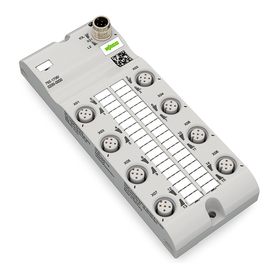
765-1706/200-000 Properties Properties 4.1 View Figure 1: View Table 1: Legend for “View” Figure Function Position Custom Name Description IO-Link class B IO-Link device and supply connection IOL (X21) IO-Link LED for connec- tion X21 2L (X21) 2L supply voltage LED (24 VDC) Product manual | Version: 2.0.0... - Page 14 Properties 765-1706/200-000 Function Position Custom Name Description Identification Data Matrix Code (DM Code) Contains the serial number of the module (UII) Digital inputs/outputs (1L X01 ... X04 Digital inputs/outputs, powered) ports X01 to X04, 2-chan- nel, M12, A-coded 1, 3, 5, 7...
-
Page 15: Connections
765-1706/200-000 Properties 4.2 Connections 4.2.1 Supply Voltage and IO-Link Table 2: Supply Voltage and IO-Link Supply Voltage and IO- Signal Description Link Communication 24 VDC supply voltage U 24 VDC auxiliary/control voltage U 1L− Reference potential for M12, A-coded, plug, 5-pin IO-Link device (data) 2L−... -
Page 16: Circuit Diagram
Properties 765-1706/200-000 4.3 Circuit Diagram The following figure shows the schematic circuit diagram of the product. Figure 2: Circuit Diagram for Each Port Product manual | Version: 2.0.0 16DIO FLD IOL-B HUB DC 24V 2.0A... -
Page 17: Technical Data
765-1706/200-000 Properties 4.4 Technical data 4.4.1 Product Table 5: Product Property Value Item Number 765-1706/100-000 Product function 16-channel digital input/output Product name (short) 16 DIO FLD IOL-B HUB 24 VDC 2.0 A Product name (long) 16-channel digital input/output; IO-Link Class B Hub;... -
Page 18: Power Supply
Properties 765-1706/200-000 Property Value Value (per UL) Self-protection Overcurrent, overload and overtemperature Maximum capacitive load 100 μF parallel to 12 Ω; 10 Hz Maximum inductive load 1.15 H / 2 A; 0.2 Hz; DC13 1.15 H / 2 A; 1 Hz; DC13; Pilot Duty Diagnostics Events: overcurrent, overload and overtemperature... -
Page 19: Electrical Safety
765-1706/200-000 Properties Property Value Value (per UL) Maximum 4.0 A with in- Maximum 3.0 A with in- creased conductor cross- creased conductor cross- section or reduced cable section or reduced cable length (max. voltage drop length (max. voltage drop of 1.2 V for either feed or of 1.2 V for either feed or... -
Page 20: Communication
Properties 765-1706/200-000 4.4.7 Communication Table 13: Communication Property Value IO-Link device type IO-Link Device Specification IO-Link V1.1.2 4.5 Derating Please note the derating for use of the IO-Link hub. The surrounding air temperature and current affect the module's heat generation. The derating curve was created with the conditions of use “without air circulation” and “mounting on poor heat conductor (wood).”... -
Page 21: Regulations And Standards
765-1706/200-000 Properties 4.6 Regulations and Standards Table 14: Standards and Regulations Standard Title EN 61000-6-2 Electromagnetic compatibility (EMC) – Immunity for industrial en- vironments EN 61000-6-4 Electromagnetic compatibility (EMC) – Emission standard for in- dustrial environments EN 61131-2 Programmable logic controllers... -
Page 22: Functions
Functions 765-1706/200-000 Functions 5.1 Process Image The following table shows the assignment of the bits of the process image to ports and pins of the hub. A pin can be configured as either a digital input or a digital output. The assignment to the input or output process data corresponds to the pin’s configuration. -
Page 23: Parameterization Tools
The WAGO I/O Field app is an app for mobile devices that can communicate with an IO-Link master of the 765 Series via Bluetooth. The IODD file of the IO-Link hub can be used by the WAGO I/O Field app to pa- rameterize the IO-Link hub. -
Page 24: Wago I/O Field App
You can find Product-specific information on the WAGO App I/O Field in the online help for the app. An iOS version of the WAGO I/O Field app is available for free in the Apple App Store, and an Android version in the Google Play Store. -
Page 25: Planning
765-1706/200-000 Planning Planning 6.1 Structure Guidelines 6.1.1 Installation Site and Touch-Proof Protection The product does not require an additional enclosure. 6.2 Power Supply Concept 6.2.1 Design Power Supply Product Power Supply and Connected Sensors/Actuators The 24 V power supplies are fed in via supply input X21 (IO-Link device connection). -
Page 26: Table 18 Io-Link Hub 765-1706/100-000 - Currents In Supply Cable 1L
Planning 765-1706/200-000 Rules In addition to the consumption of the connected devices, rules for the maximum load ca- pacity of supply input X21 and all connection contacts (pins) must be observed to avoid damage to the product. Because of the galvanic isolation (if available), the values for supply cables 1L and 2L must be viewed separately. -
Page 27: Table 19 Io-Link Hub 765-1706/100-000 - Currents In Supply Cable 2L
765-1706/200-000 Planning Table 19: IO-Link Hub 765-1706/100-000 – Currents in Supply Cable 2L Current Description Current at the IO-Link device/supply voltage input (X21). X21_2L Current 2L+ / reverse current 2L− Total current for supply cable 2L at digital input/output X0i (i.e., port X03, X04) corresponds to... -
Page 28: Connection Example
The figure below shows how an IO-Link hub is connected to an IO-Link master and how it is connected to the real-time ETHERNET and supplied with operating voltage (+24 V): Figure 5: Connection Example of an IO-Link Hub 765-1706/200-000 to an IO-Link Master Product manual | Version: 2.0.0... -
Page 29: Settings Options
IO-Link devices. The PDCT is used to make all hub settings. If you are using an IO-Link master from WAGO, the WAGO IO-Link Configurator software is available as a PDCT. Alternatively, if you have a 765-410x device connected as a hub 8 WAGO I/O Field... -
Page 30: Configuration Of The Substitute Value Behavior For The Digital Outputs
Planning 765-1706/200-000 For each connection of the IO-Link hub that is configured as an input in the port configu- ration, you can use the DI Inversion Configuration (index 75) to invert its signal or cancel the inversion; see section 8 Index 75 (0x4B) - "DI Inversion Configuration" Object [} 61]. -
Page 31: Behavior In The Event Of A Communication Interruption
765-1706/200-000 Planning Dynamic Data This includes the following device configuration data: • The current port configuration • The current configuration of the input filters • The current configuration of the signal inversion of the inputs • The current configuration of the fail-safe behavior of the outputs •... -
Page 32: Transport And Storage
Transport and Storage 765-1706/200-000 Transport and Storage The original packaging offers optimal protection during transport and storage. • Store the product in suitable packaging, preferably the original packaging. • Only transport the product in suitable containers/packaging. • Make sure the product contacts are not contaminated or damaged during packing or unpacking. -
Page 33: Installation And Removal
765-1706/200-000 Installation and Removal Installation and Removal 8.1 Installation 8.1.1 Tools Required for Installation The following tools are required for installation: • Allen wrench for the M4 hex head mounting screws The following additional items are only required for installation where no threaded hole is present: •... -
Page 34: Note On Protecting Against Heat Generation By The Product
Installation and Removal 765-1706/200-000 • When mounting, be sure not to contaminate the connections. The contamination dam- ages the contacts, which can limit the reliability of the contacts. 8.1.4 Note on Protecting against Heat Generation by the Product During operation, the product can get hot! Therefore, always note the following informa- tion: •... -
Page 35: Before Removal
765-1706/200-000 Installation and Removal 8.2.2 Before Removal CAUTION Device is hot During operation, high surface temperatures can occur on the housing and the metal con- nection sockets. If the product has been in operation, allow it to cool before touching the product or use gloves. -
Page 36: Connection
IP67. 9.2 Connect Cables WAGO recommends using the connecting cables, connectors and accessories from the 756 Series. which have been tailored specifically to the WAGO I/O System Field. The tightening torques given in 8 Connection Technology [} 17] apply to the pluggable connectors of the connecting cables. -
Page 37: Connect Sensors/Actuators
8 Supply Voltage and IO-Link be found in section [} 15]. WAGO recommends using pre-assembled cables. The 1L power supply must be connected to the product. If this supply voltage is switched off, the product does not work. Power supply 2L is required to power actuators. It is only required on the products whose outputs are to be switched off separately. -
Page 38: Table 22 Connecting Digital Inputs/Outputs
Connection 765-1706/200-000 IOLS DIO B DIO B DIO A DIO A DIO B DIO B DIO A DIO A DIO B DIO B DIO A DIO A DIO B DIO B DIO A DIO A Figure 6: Schematic Circuit Diagram of the Power Supply The following table shows the connection options for digital inputs and outputs. - Page 39 765-1706/200-000 Connection Connection Option Description Connection of two digital inputs on channels A and B. Required port configuration: pin 4 and pin 2 as digital inputs. Connection of a digital output on channel A. Required port configuration: pin 4 as a digital output and pin 2 disabled.
-
Page 40: Commissioning
10.1.1 Parameterizing a Module with the WAGO I/O Field App Note Read the online help! You can find Product-specific information on the WAGO App I/O Field in the online help for the app. 10.1.2 IO-Link Object Directories The parameters are set using the ISDU mechanism (ISDU = Indexed Service Data Units) described in the IO-Link specification. - Page 41 765-1706/200-000 Commissioning Index Subindex Object Name Access Length Description Default Value (in Bytes) Vendor Name R Name of the Wago GmbH vendor & Co. KG Vendor Text Additional in- Wago IO-Link formation on Hubline the vendor Product Name R Product identi-...
- Page 42 Commissioning 765-1706/200-000 Index Subindex Object Name Access Length Description Default Value (in Bytes) Supply Cur- Current on the rent supply cable (pin 1) DIO Current 8/16*4 Current at the digital inputs and outputs Failsafe Con- 8/16*1 Configuration figuration of the failure...
-
Page 43: Index 0 (0X0) - "Direct Parameter Page 1" Object
(in bytes) 0 (0x00) Direct Param- Direct parame- eter Page 1 ter page 1 0 (0x00) Vendor ID Manufacturer 0x011D ID - WAGO 0 (0x00) 0 (0x00) Device ID Module ID: 0x80 Part 1 0 (0x00) 10/ 0xA Module ID:... -
Page 44: Index 3 (0X03) - "Data Storage Index" Object
Commissioning 765-1706/200-000 10.1.2.4 Index 3 (0x03) - "Data Storage Index" Object This index cannot be read, only written to. It is used to receive system commands for pa- rameterization and data storage. The following values are accepted by the module as system commands if they are written in index 02: Table 26: Index 3 (0x03) - "Data Storage Index"... -
Page 45: Table 29 Coding Of The State Of Data Storage
765-1706/200-000 Commissioning Table 29: Coding of the state of data storage Bit 1 Bit 2 Description Disabled Upload enabled Download enabled Data storage (DS) locked The meaning of the DS_UPLOAD_FLAG (bit 7) is as follows: Table 30: Meaning of the DS_UPLOAD_FLAG DS_UPLOAD_FLAG... -
Page 46: Index 12 (0X0C) - "Device Access Locks" Object
Commissioning 765-1706/200-000 Each index list can hold up to 70 entries. Index lists can be linked using the termination marker. 10.1.2.5 Index 12 (0x0C) - "Device Access Locks" Object Table 32: Index 12 (0x0C) - "Device Access Locks" Object Index Subindex... -
Page 47: Index 13 (0X0D) - "Profile Characteristics" Object
765-1706/200-000 Commissioning 10.1.2.6 Index 13 (0x0D) - "Profile Characteristics" Object Table 33: Index 13 (0x0D) - "Module Profile Characteristics" Object Index Subindex Name Access Length Description Default value (in bytes) 13 (0x0D) Profile charac- Characteristic teristics of the module profile (12 entries of... -
Page 48: Index 37 (0X25) - "Detailed Service Status" Object
Commissioning 765-1706/200-000 10.1.2.9 Index 37 (0x25) - "Detailed Service Status" Object Table 37: Index 37 (0x25) - "Detailed Service Status" Object Index Subindex Name Access Length Description (in bytes) 37 (0x25) Detailed service Detailed service status status (returns 24 times 3 bytes) -
Page 49: Index 65 (0X41) - "Di Filter Configuration" Object
765-1706/200-000 Commissioning 10.1.2.11 Index 65 (0x41) - "DI Filter Configuration" Object For each port of the IO-Link hub that is configured as an input in the port configuration, you can use the DI Filter Configuration object to configure the integral filter time or to switch off the filter entirely. -
Page 50: Index 66 (0X42) - "Test Input/Output" (Test Io) Object
Commissioning 765-1706/200-000 10.1.2.12 Index 66 (0x42) - “Test Input/Output” (Test IO) Object The "Test IO" object enables the following: • Enables and disables test mode • Reads the digital inputs • Writes the digital outputs • Reads back the digital outputs •... - Page 51 Writing the value 0 clears the flag and switches back to normal operation. Use the following options only if requested to do so by WAGO customer service. 66 (0x42) Write register Write data value (main register to address of...
- Page 52 Commissioning 765-1706/200-000 Index Subindex Name Access Length Description (in bytes) 66 (0x42) Write register Write data value (second register to address of the set) second register set, 8 bytes of data consisting of 4 bytes of ad- dress and 4...
-
Page 53: Index 67 (0X43) - "Test Event" Object
765-1706/200-000 Commissioning 10.1.2.13 Index 67 (0x43) - "Test Event" Object The test event object enables IO-Link events to be triggered for test purposes, which are sent to the IO-Link master. Table 44: Index 67 (0x43) - "Test Event" Object Index Subindex... -
Page 54: Index 69 (0X45) - "Supply Voltage (Pin 1)" Object
Commissioning 765-1706/200-000 10.1.2.15 Index 69 (0x45) - "Supply Voltage (Pin 1)” Object The Supply Voltage – Pin 1 object makes it possible to read the measured values of the current supply voltage of the hub device’s ports in mV. The values are specified as un- signed 32 bit values. - Page 55 765-1706/200-000 Commissioning Index Subindex Name Access Length Description (in Bytes) 70 (0x46) Voltage of the Digital input/out- digital input/out- put voltage at put at port X03, port X03, pin 2 pin 2 70 (0x46) Voltage of the Digital input/out- digital input/out-...
-
Page 56: Index 71 (0X47) - "Supply Current" Object
Commissioning 765-1706/200-000 10.1.2.17 Index 71 (0x47) - "Supply Current" Object The Supply Current – Pin 1 object makes it possible to read the measured values of the current supply currents at pin 1 of the respective port of the hub device in mA. The values are given as unsigned 32 bit values. -
Page 57: Index 72 (0X48) - "Current At The Digital Inputs And Outputs" Object (Dio Current)
765-1706/200-000 Commissioning 10.1.2.18 Index 72 (0x48) – “Current at the Digital Inputs and Outputs” Object (DIO Current) The “DIO Current (Current at the Digital Inputs and Outputs)” object makes is possible to read the measured values for the present currents at pins 4 and 2 of the ports in mA. The values are specified as unsigned 32 bit values. -
Page 58: Index 73 (0X49) - "Configuration Of The Substitute Value Behavior For The Digital Outputs" Object
Commissioning 765-1706/200-000 Index Subindex Name Access Length Description (in Bytes) 72 (0x48) Current of the Digital input/out- digital input/out- put current at put at port X06, port X06, pin 2 pin 2 72 (0x48) Current of the Digital input/out- digital input/out-... -
Page 59: Table 52 Configuration Of The Behavior Of The Digital Outputs In The Event Of An Error
765-1706/200-000 Commissioning Index Subindex Name Access Length Description Default Value (in Bytes) 73 (0x49) Substitute Value for con- 0 (low value) value behavior figuration of for port X08, the substitute pin 4 value behav- ior: 0, 1, 2 73 (0x49) -
Page 60: Table 53 Index 74 (0X4A) - Internal Supply Voltage
Commissioning 765-1706/200-000 Table 53: Index 74 (0x4A) – Internal Supply Voltage Index Subindex Object Name Access Length Meaning / De- (in Bytes) fault Value 74 (0x4A) Internal supply Internal supply voltage voltage 74 (0x4A) VDDD, first IO- Allows the VDDD Link chip... -
Page 61: Index 75 (0X4B) - "Di Inversion Configuration" Object
765-1706/200-000 Commissioning 10.1.2.21 Index 75 (0x4B) - "DI Inversion Configuration" Object The Digital Inversion Configuration (DI Inversion Configuration) object makes it possible to invert the input signal at a pin of a specific port. If the configuration bit is set, then the corresponding input signal is inverted within the process data. -
Page 62: Index 76 (0X4C) - "Debug Information" Object
Commissioning 765-1706/200-000 10.1.2.22 Index 76 (0x4C) - "Debug Information" Object The Debug Informations object provides detailed information on the IO-Link stack and the IO-Link application. Table 56: Index 76 (0x4C) - "Debug Information" Object Index Subindex Name Access Length Description (in bytes) -
Page 63: Diagnostics
765-1706/200-000 Diagnostics Diagnostics 11.1 Diagnostics via Indicators The status of the connected sensors and actuators, malfunctions in communication and the status of the power supply to the sensors and actuators can be identified via the vis- ual diagnostics. Power Supply Status Table 57: 2L Status (Class B) -
Page 64: Diagnostics Via Io-Link
Diagnostics 765-1706/200-000 Color State Description Overload, short circuit through sensor/actu- ator (pin 4 and pin 3) If the LED of channel A is red at the same time: Overload, short circuit at the supply con- nection (pin 1 and pin 3) IO-Link Device Status Table 60: IO-Link Device Status... - Page 65 765-1706/200-000 Diagnostics Event Number Event Type Event Type Explanation 0x8CA3 Incoming, outgoing Warning Port X02 pin 4: Power sup- ply restricted / switched off due to overcurrent 0x8CA4 Incoming, outgoing Warning Port X03 pin 2: Power sup- ply restricted / switched off...
-
Page 66: Table 62 Io-Link Events For Monitoring Against Undervoltage And Overvoltage
Diagnostics 765-1706/200-000 Event Number Event Type Event Type Explanation 0x8CD5 Incoming, outgoing Warning Port X06 pin 1: Power sup- ply restricted / switched off due to overcurrent 0x8CD6 Incoming, outgoing Warning Port X07 pin 1: Power sup- ply restricted / switched off... -
Page 67: Table 63 Io-Link Events Of The Overtemperature Monitoring
765-1706/200-000 Diagnostics Table 63: IO-Link events of the overtemperature monitoring Event Num- Event Type Event Type Description 0x4000 incoming Error Overload temperature Limit of 105 °C exceeded; ports are switched off. outgoing Error Overload temperature Fell below limiting value of 100 °C. Ports are switched on again. -
Page 68: Service
12.1 Update Firmware The product’s firmware can be updated. Use the WAGO IO-Link Configurator for this. ü The IO-Link hub is connected to a WAGO IO-Link master and both modules are ready for operation. ü The IO-Link master can be reached via ETHERNET. - Page 69 765-1706/200-000 Service 8. In the Resource list, select the file that matches the hub type, e.g., Wago_765_170x.zip. 9. Click [Update Firmware]. ð A message and query are displayed. 10. Click [OK] to start the update. ð The progress is displayed as text in Status.
-
Page 70: Decommissioning
Decommissioning 765-1706/200-000 Decommissioning 13.1 Disposal and Recycling Table 64: WEEE Mark Logo Description Electrical and electronic equipment may not be disposed of with household waste. This also applies to products without this mark. Electrical and electronic equipment contain materials and substances that can be harmful to the environment and health. -
Page 71: Appendix
765-1706/200-000 Appendix Appendix 14.1 Protected Rights ® ® • Adobe and Acrobat are registered trademarks of Adobe Systems Inc. • Android is a trademark of Google LLC. • Apple, the Apple logo, iPhone, iPad and iPod touch are registered trademarks of Apple Inc. -
Page 72: List Of Tables
List of Tables 765-1706/200-000 List of Tables Table 1 Legend for “View” Figure ....................Table 2 Supply Voltage and IO-Link ....................Table 3 Digital input/output (2-channel, 1L powered) ..............Table 4 Digital input/output (2-channel, 2L powered) ..............Table 5 Product.......................... - Page 73 765-1706/200-000 List of Tables Table 37 Index 37 (0x25) - "Detailed Service Status" Object ............Table 38 Index 64 (0x40) – “Port Configuration” Object ..............Table 39 Configuration of the 16 Digital Inputs or Outputs ............... Table 40 Index 65 (0x41) – “Digital Input Filter Configuration” Object (DI Filter Configuration) ..
-
Page 74: List Of Figures
Derating of a contact (pin) of the A-coded connections (for core cross-section = 0.34 mm /AWG 22) ....................... Figure 5 Connection Example of an IO-Link Hub 765-1706/200-000 to an IO-Link Master..Figure 6 Schematic Circuit Diagram of the Power Supply ............Product manual | Version: 2.0.0... - Page 75 765-1706/200-000 List of Figures Product manual | Version: 2.0.0 16DIO FLD IOL-B HUB DC 24V 2.0A...
- Page 76 WAGO is a registered trademark of WAGO Verwaltungsgesellschaft mbH. Copyright – WAGO GmbH & Co. KG – All rights reserved. The content and structure of the WAGO websites, catalogs, videos and other WAGO media are subject to copyright. Distri- bution or modification of the contents of these pages and videos is prohibited. Furthermore, the content may neither be copied nor made available to third parties for commercial pur-...
Need help?
Do you have a question about the 765-1706/200-000 and is the answer not in the manual?
Questions and answers