Toshiba TS3000 Series Instruction Manual
Vertical articulated robot system controller
Hide thumbs
Also See for TS3000 Series:
- Instruction manual (368 pages) ,
- Communications manual (174 pages) ,
- Instruction manual (355 pages)
Table of Contents
Advertisement
Quick Links
TS3100 6-AXIS system
INSTRUCTION MANUAL
(Vertical Articulated Robot System)
• Make sure that this instruction manual is delivered to the
final user of Toshiba Machine's industrial robot.
• Before operating the industrial robot, read through and
completely understand this manual.
• After reading through this manual, keep it nearby for future
reference.
OPERATOR'S MANUAL
Notice
TOSHIBA MACHINE CO., LTD.
STE 80730-0
Advertisement
Table of Contents

Related Manuals for Toshiba TS3000 Series


Summary of Contents for Toshiba TS3000 Series
- Page 1 (Vertical Articulated Robot System) Notice • Make sure that this instruction manual is delivered to the final user of Toshiba Machine's industrial robot. • Before operating the industrial robot, read through and completely understand this manual. • After reading through this manual, keep it nearby for future reference.
- Page 2 Robot Controller OPERATOR’S MANUAL Copyright 2008 by Toshiba Machine Co., Ltd. All rights reserved. No part of this document may be reproduced in any form without obtaining prior written permission from Toshiba Machine Co., Ltd. The information contained in this manual is subject to change without prior notice to effect improvements.
- Page 3 series Robot Controller OPERATOR’S MANUAL Preface Structure of TS series robot controller instruction manuals: These instruction manuals were published in parts according to the application and purpose, and the name and outline of each manual are as follows: [Safety Manual] This manual contains the important information to use the robot safety and correctly.
- Page 4 series Robot Controller OPERATOR’S MANUAL [Communication Manual] This manual describes the serial communication between the robot controller and other equipment. Refer to this manual when connecting the robot controller with a host computer, optical sensor, etc., via a serial cable. [User Parameter Manual] This manual describes the setting procedures of the robot controller.
- Page 5 series Robot Controller OPERATOR’S MANUAL Cautions on Safety This manual contains the important information on the robot and controller to prevent injury to the operators and persons nearby, to prevent damage to assets and to assure correct use. Make sure that the following details (indications and symbols) are well understood before reading this manual.
- Page 6 series Robot Controller OPERATOR’S MANUAL [Operation] DANGER • During operation, NEVER enter the dangerous area of the robot. Otherwise, you will be injured seriously. • DO NOT leave in the working range any machinery or materials Prohibited which will hinder the operation. If the equipment went wrong, a person nearby will be injured or involved in an accident.
- Page 7 series Robot Controller OPERATOR’S MANUAL CAUTION • DO NOT change the data of the system structure file. Otherwise, the robot will move abnormally, resulting in damage or an accident. Prohibited • In principle, teaching operation should be performed outside the dangerous area of the robot.
- Page 8 series Robot Controller OPERATOR’S MANUAL CAUTION • Before operating the equipment, perform the following inspection. (1) Make sure that visual appearance of the robot, controller, peripheral equipment and cables is in the good condition. Mandatory (2) Make sure that no obstacle stands in or near the working range of the robot and peripheral equipment.
-
Page 9: Table Of Contents
series Robot Controller OPERATOR’S MANUAL Table of Contents Page Section 1 Before Operating Your Robot ............Overview of Operation Functions............Mode Structure ..................1.2.1 External Automatic Mode ............1.2.2 Internal Automatic Mode............1.2.3 Teaching Mode (Including Test Operation) ......1.2.4 Edit .................. - Page 10 series Robot Controller OPERATOR’S MANUAL Page Section 3 Teaching Operation ................ Selecting the Teaching Mode .............. Guidance Coordinates ............... Guide Mode ..................Guide Speed..................Guidance ..................... Servo Free ................... Section 4 Program Editing................Starting Up the Program Editor [EDIT]..........Character Input ..................4.2.1 Character Input Mode Selection ..........
- Page 11 series Robot Controller OPERATOR’S MANUAL Page Section 5 Data Editing ..................Starting Up the Data Editor ..............Position Data Directory Display Mode..........5.2.1 Editing of Position Data Name..........5.2.2 Editing of Position Element............. 5-10 5.2.3 Addition of New Position Data (INS)........5-14 5.2.4 Deletion of Position Data (ALT + BS) ........
- Page 12 series Robot Controller OPERATOR’S MANUAL Page 5.5.2 Editing of Coordinate Element ..........5-68 5.5.3 Teaching of Coordinate Data [TEACH]........5-71 Load Data Display Mode..............5-77 5.6.1 Editing of Load Data Name ............ 5-80 5.6.2 Editing of Load Element ............5-83 5.6.3 Addition of New Load Data [INS] ..........
- Page 13 series Robot Controller OPERATOR’S MANUAL Page Section 7 Internal Automatic Operation............Selecting Internal Automatic Operation Mode........Selecting File [SEL]................Selecting Run Mode [MODE]............... Speed Override [OVRD] ..............Startup ....................7-10 Stop ..................... 7-11 7.6.1 Cycle Stop ................7-11 7.6.2 STOP..................7-12 7.6.3 BREAK ...................
- Page 14 series Robot Controller OPERATOR’S MANUAL Page Section 9 File Operation ................. Directory Display [DIR] ..............File Copy [COPY]................File Rename [REN] ................File Delete [DEL] ................9-12 Section 10 Utility....................10-1 10.1 Selecting Utility Mode................ 10-1 10.2 Auxiliary Signal Display [AUX]............10-4 10.3 External Input/Output Signal Display [I/O] .........
- Page 15 series Robot Controller OPERATOR’S MANUAL Page Section 11 Self-Diagnosis ................11-1 11.1 Classification of Errors ..............11-1 11.2 Display at Error Generation............... 11-1 11.3 Error Display ..................11-2 11.4 Error Reset..................11-4 11.5 All Errors Reset ................. 11-5 11.6 Error History Display ................. 11-6 11.7 Compile Error Display ...............
-
Page 16: Before Operating Your Robot
series Robot Controller OPERATOR’S MANUAL Section 1 Before Operating Your Robot Overview of Operation Functions External HOST Control Teach Function Descriptions control commu- panel pendant signal nication Main power ON/OFF Used to turn on and off the main power. Δ Servo power Used to turn on and off the servo ON/OFF... - Page 17 series Robot Controller OPERATOR’S MANUAL External HOST Control Teach Function Descriptions control commu- panel pendant signal nication Work coordinate Used to select the work coordinate system selection system. Tool coordinate Used to select the tool coordinate system selection system. Present position Used to display the present position of monitor the robot in each coordinate system.
-
Page 18: Mode Structure
series Robot Controller OPERATOR’S MANUAL Mode Structure External automatic Used to perform automatic programmed mode operation by means of using external signals (EXERNAL) or communication. Master Internal automatic Used to perform automatic programmed mode mode operation through the control panel or teach (INTERNAL) pendant. - Page 19 series Robot Controller OPERATOR’S MANUAL 1.2.1 External Automatic Mode INTERNAL TEACHING EMERGENCY SERVO SERVO POWER STOP The external automatic mode comes in the three (3) sub modes as shown below. The selection of these modes is carried out LINE using the user parameter. SELECT USER ALARM...
-
Page 20: Internal Automatic Mode
series Robot Controller OPERATOR’S MANUAL 1.2.2 Internal Automatic Mode File selection Used to select a file to be executed. (SEL) Run mode Used to select a run mode. selection (MODE) Speed override Used to set the speed override. (OVRD) Internal Start Used to start program execution from the automatic... -
Page 21: Teaching Mode (Including Test Operation)
series Robot Controller OPERATOR’S MANUAL 1.2.3 Teaching Mode (Including Test Operation) Program edit Used to edit programs. (EDIT) Data edit Used to edit various data (position, (DEDIT) coordinate and load). File selection Used to select a file to be executed. (SEL) Teaching Start... -
Page 22: Edit
series Robot Controller OPERATOR’S MANUAL 1.2.4 Edit Program editor Program editing. Used to edit programs and global data by character input, command menu selection and SCOL menu selection. Edit Position data editing. Used to edit position data by teaching and numerical value input. -
Page 23: General Operation
series Robot Controller OPERATOR’S MANUAL General Operation The key seat array of the teach pendant is as shown below. Guide keys (X, Y, Z, A, B, C) Cursor keys are expressed by in this manual. STE 80730 – 1-8 –... -
Page 24: Entry Of Alphanumeric Characters And Symbols
series Robot Controller OPERATOR’S MANUAL 1.3.1 Entry of Alphanumeric Characters and Symbols The alphabet input mode and numeric input mode can be changed over alternately by pressing the ALPH key. While the numeric input mode is selected, the key lamp is illuminated. (1) Numeric key input Select the numeric input (NUM) mode and press a desired key. -
Page 25: Combined Key Operation
series Robot Controller OPERATOR’S MANUAL codes that can be input are grouped according to each mode. (2)–3 Keys relating to unsettled characters Used to cancel an unsettled character or characters. Used to cancel an unsettled character or characters. Used to determine an unsettled character or characters. Used to select a choice before current character string. -
Page 26: Use Of Function Keys
series Robot Controller OPERATOR’S MANUAL 1.3.3 Use of Function Keys The teach pendant is provided with five (5) function keys (F1 ~ F5) to facilitate command input. The functions to which F1 to F5 correspond will change with the mode selected. The command menu corresponding to each function key is displayed at the bottom of the display. -
Page 27: Repeating An Entry
series Robot Controller OPERATOR’S MANUAL 1.3.4 Repeating an Entry The repeat function allows entry of repeated operation by pressing the same key continuously. The following keys are available for the repeat operation. • Cursor keys (The keys can be moved rapidly by the repeat function.) •... -
Page 28: Canceling An Entry
series Robot Controller OPERATOR’S MANUAL 1.3.6 Canceling an Entry If you wish to cancel the command you are entering, press the ESC key. This cancels the command you have entered and allows you to input the next command on the following line. Should an error message or other such message appear during command input, that command line is canceled. -
Page 29: Format For Operating Instructions
series Robot Controller OPERATOR’S MANUAL 1.3.8 Format for Operating Instructions The following format is used in this manual to explain how to use commands. Title [Command name] (1) Function Explains the function and application. (2) Operating procedures Explains the procedures and system response for various operations. -
Page 30: Assigning Names
series Robot Controller OPERATOR’S MANUAL Assigning Names 1.4.1 Assigning a File Name Every file registered in the RAM drive has its own name. This is called the file name. Generally, the file name has the following format. SYSTEM ._ PAR File name extension (1 ~ 3 characters) Period File name (1 ~ 8 characters) -
Page 31: Assigning A Point Name
series Robot Controller OPERATOR’S MANUAL 1.4.2 Assigning a Point Name When entering positional data for a point, you have to assign a name to that point. This name is used later in the program when teaching the robot where to go. Generally, the point name has the following format. -
Page 32: Assigning A Name To Coordinate Data
series Robot Controller OPERATOR’S MANUAL 1.4.3 Assigning a Name to Coordinate Data When entering coordinate data for the work coordinate system, tool coordinate system or base coordinate system, you have to assign a coordinate name to that data. A coordinate of each coordinate system is specified by the coordinate name. Generally, the coordinate name has the following format. -
Page 33: Assigning A Name To Load Data
series Robot Controller OPERATOR’S MANUAL 1.4.4 Assigning a Name to Load Data When entering load data, you have to assign a load name to that data. A load in the program is specified by the load name. Generally, the load name has the following format. SAMPLE1 Load name (1 ~ 10 characters) The following characters can be used for the coordinate name. -
Page 34: File
series Robot Controller OPERATOR’S MANUAL File To move the robot, robot language programs, position data and parameters should be registered beforehand in the controller RAM drive (memory). All of these programs and data are handled on the basis of a file. 1.5.1 Kind of File The following files are used in the robot system. - Page 35 series Robot Controller OPERATOR’S MANUAL (7) Automatic start file (AUTOSTR. BAT) A kind of batch file, it is automatically executed when the controller power is turned on. (8) Program file A file stating the robot motions. It saves position data and programs created by the robot language.
-
Page 36: Batch File
series Robot Controller OPERATOR’S MANUAL 1.5.2 Batch File The controller is provided with a function executing a series of commands in the pack, which is called the "batch processing." To execute the batch processing, commands should be written in the file in the order of execution. This file is generally referred to as the "batch file."... -
Page 37: Basic Operation
series Robot Controller OPERATOR’S MANUAL Section 2 Basic Operation Basic Operating Procedures The following flow chart shows the basic operating procedures for automatic operation. It covers all operations from turning on the main power to turning off the main power. Start Main power ON Servo power ON... -
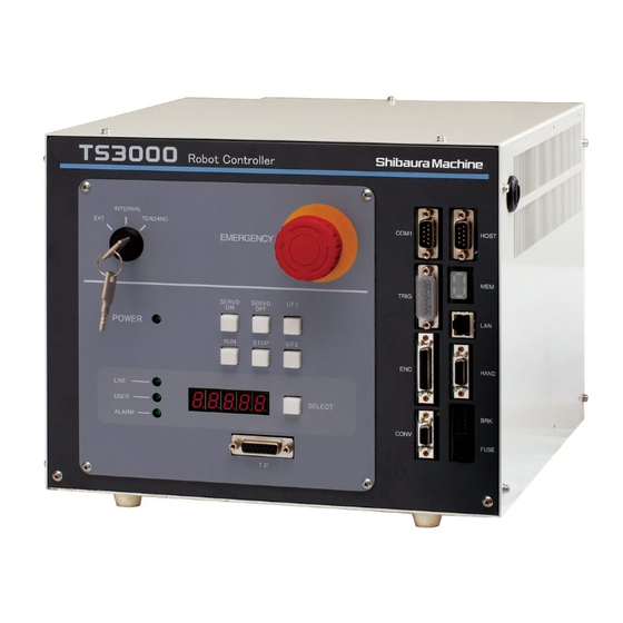
Page 38: Control Panel
series Robot Controller OPERATOR’S MANUAL Control Panel The control panel is shown below. INTERNAL TEACHING EMERGENCY SERVO SERVO POWER STOP LINE USER SELECT ALARM (1) Key switch : Used to select the operation master mode. (2) SERVO ON, SERVO OFF : Used to turn on and off the servo power. - Page 39 series Robot Controller OPERATOR’S MANUAL displayed at intervals of two (2) seconds. When an alarm occurs, this switch flashes. (6) UF1, UF2 : User function switches. This switch input can be referred to by DIN and the lamp output by DOUT. (7) EMERGENCY : EMERGENCY stop pushbutton switch.
-
Page 40: Turning On The Main Power
series Robot Controller OPERATOR’S MANUAL Turning ON the Main Power CAUTION If an abnormality has generated or the POWER LED lamp on the control panel remains off after the main power switch of the controller was turned on, turn off the main power immediately and confirm the wiring. - Page 41 series Robot Controller OPERATOR’S MANUAL (3) Cautions • The following reserved files are required in the RAM drive. MACHINE. PAR SCOL. LIB * EXTRNSEL. PAR* SERVO. PAR AUTOSTR. BAT * ETHERNET. PAR* ROBOT. PAR PALLET. LIB * CONVEYOR. PAR* USER. PAR •...
- Page 42 series Robot Controller OPERATOR’S MANUAL Turning ON the Servo Power CAUTION • If the robot moves abnormally at servo power ON, immediately press the EMERGENCY stop pushbutton switch to turn the servo power off. • If you enters the dangerous area of the robot, turn off the servo power beforehand.
- Page 43 series Robot Controller OPERATOR’S MANUAL (3) Cautions • While the EMERGENCY stop switch is pressed, the servo power will not turn on. Be sure to cancel an emergency stop before turning on the servo power. • The servo power can be turned on through the teach pendant only when the teaching mode is selected.
-
Page 44: Turning On The Servo Power
series Robot Controller OPERATOR’S MANUAL Turning OFF the Servo Power (1) Function Turns off the main circuit power of the servo driver. The servo-controlled axes are set free and any brake is activated. (2) Procedures (a) Step 1: Turning off the servo power. Press the SERVO OFF switch on the control panel. -
Page 45: Turning Off The Main Power
series Robot Controller OPERATOR’S MANUAL Turning OFF the Main Power (1) Function Turns off the main power and stops controller processing. (2) Procedures (a) Step 1: Turning off the main power. Set the MAIN POWER switch on the controller to the OFF position, and the INTERNAL “POWER”... -
Page 46: Teaching Operation
series Robot Controller OPERATOR’S MANUAL Section 3 Teaching Operation Selecting the Teaching Mode (1) Function Changes over to the teaching mode in which the robot is manually guided, points are taught, files are operated and the system is controlled. (2) Procedures (a) Step 1: Teaching mode selection. -
Page 47: Program Editing
series Robot Controller OPERATOR’S MANUAL When the teaching mode is selected, the following display appears. M O D E : T E A C H I N G / C O N T 2 0 % M : F R E E S : S T O P R E S E T E D I T... - Page 48 series Robot Controller OPERATOR’S MANUAL Guidance Coordinates (1) Function Selects a coordinate system in which the robot is guided, from among the joint, tool, work and world coordinate systems. (2) Procedures (a) Step 1: Selection of tool or work coordinate system. Select the work or tool coordinate system used for [TRANS] of the utility function.
- Page 49 series Robot Controller OPERATOR’S MANUAL Guide Mode The guide mode comes in three (3) types; JOG, INCHING and FREE. • In the JOG mode, the robot moves in a specified direction at a specified speed in a selected coordinate system as long as the corresponding guide key is kept pressed.
- Page 50 series Robot Controller OPERATOR’S MANUAL Guide Speed (1) Function Selects the speed or travel distance for manual guide. When the JOG mode is selected, speed selection becomes effective. When the INCHING mode is selected, travel distance selection prevails. Select the speed or travel distance according to the distance to the target position.
- Page 51 series Robot Controller OPERATOR’S MANUAL Guidance CAUTION • When guiding the robot manually, DO NOT enter the dangerous area of the robot. • If the robot moves abnormally, immediately effect an emergency stop. (1) Function While the JOG or INCHING mode is selected, the robot can be moved in a desired direction by pressing the appropriate guide key.
- Page 52 series Robot Controller OPERATOR’S MANUAL Servo Free The SERVO FREE function is not currently provided with the robot controller. (1) Function In the FREE mode, it is possible to cancel a servo lock of any axis to make it servo-free. The axis thus set servo-free can be moved by hand. This is convenient when moving the robot near a workpiece, etc.
- Page 53 series Robot Controller OPERATOR’S MANUAL (3) Cautions • When you select the RUN mode, direct execution mode, internal automatic mode or external automatic mode while the servo lock is canceled, servo lock is effected on all axes. • The guide keys are operative only when they are pressed with the servo being turned on.
-
Page 54: Starting Up The Program Editor [Edit]
series Robot Controller OPERATOR’S MANUAL Section 4 Program Editing Starting Up the Program Editor [EDIT] (1) Function Starts up the program editor to edit a program. (2) Procedures (a) Step 1: Mode selection. Change over the MODE switch equipped on the control panel to select "TEACHING."... - Page 55 series Robot Controller OPERATOR’S MANUAL Step 3: File selection. Select the file name by means of the up and down cursor keys. To create a new file, press [NEW]. E D I T ( 0 0 1 / 2 5 6 ) A B C D 1 2 3 4 .
- Page 56 series Robot Controller OPERATOR’S MANUAL (d) Step 4: Check the file name to be edited. Check for the name of a file to be edited to make sure that you are dealing with the right file. If OK, press the EXE key. Unless the specified file is present in the RAM drive, you can create a new file.
- Page 57 series Robot Controller OPERATOR’S MANUAL M O D E : T E A C H I N G / C O N T 1 2 3 4 5 6 7 8 . 1 2 3 L : 9 9 9 9 O : 1 0 0 % M : F R E E S : S T O P...
-
Page 58: Character Input
series Robot Controller OPERATOR’S MANUAL Character Input 4.2.1 Character Input Mode Selection (1) Function This mode allows characters to be entered at the cursor position on the editing display through the keyboard. Edit commands can be input directly. (2) Procedures (a) Step 1: Mode selection. -
Page 59: Insert Mode [Ins]
series Robot Controller OPERATOR’S MANUAL 4.2.2 Insert Mode [INS] (1) Function Used to select the insert mode for character input. A character entered through the keyboard is inserted to the cursor position. (2) Procedures (a) Step 1: INS key operation. Each time the INS key is pressed, the input mode or replace mode is selected alternately. - Page 60 series Robot Controller OPERATOR’S MANUAL (3) Related functions (Line insert) • Line insertion While the insert mode is selected, move the cursor to the top of a line where a character or characters are to be added, using the cursor keys (↑, ↓, ←, →).
- Page 61 series Robot Controller OPERATOR’S MANUAL When the available memory space becomes small during editing operation, a warning saying "A few memory remains" is displayed. When this happens, quit the program editing mode, delete any unnecessary file or files, then resume the program editing operation. If character input continues with the warning of "A few memory remains"...
-
Page 62: Replace Mode [Replace]
series Robot Controller OPERATOR’S MANUAL 4.2.3 Replace Mode [Replace] (1) Function Used to select the replace mode for character input. A character entered through the keyboard is replaced with the one at the cursor position. (2) Procedures (a) Step 1: INS key operation. - Page 63 series Robot Controller OPERATOR’S MANUAL (3) Cautions • When the program editor has started up, the insert mode takes effect. • The insert mode is discriminated from the replace mode by the shape of the cursor. Insert mode Replace mode STE 80730 –...
-
Page 64: Input Correction [Bs]
series Robot Controller OPERATOR’S MANUAL 4.2.4 Input Correction [BS] (1) Function While the character input mode is selected, one (1) character just before the cursor position can be deleted on the editing display. This function is useful for deleting an error just after key entry. (2) Procedures (a) Step 1: Input correction. -
Page 65: Character Deletion [Del]
series Robot Controller OPERATOR’S MANUAL 4.2.5 Character Deletion [DEL] (1) Function Deletes one (1) character at the cursor position. (2) Procedures (a) Step 1: Designation of deleted character. Move the cursor to a character to be deleted. P R G R A M . N A M C : 5 L : 1 P R O G H R A M... -
Page 66: Moving The Cursor [↑] [↓] [←] [→]
series Robot Controller OPERATOR’S MANUAL 4.2.6 Moving the Cursor [↑] [↓] [←] [→] (1) Function Moves the cursor by one (1) character in the arrow-marked direction. (2) Procedures (a) Step 1: Cursor movement P R O G R A M SPEED = 50 MOVE PNT21... -
Page 67: Edit Command Input
series Robot Controller OPERATOR’S MANUAL Edit Command Input Edit commands can be input, using function keys. 4.3.1 List of Edit Commands Menu Descriptions [SAVE] Quit Saves the data and quits the editor. [DEDIT] Changes over to the data editor screen. [JUMP] Moves the cursor to specified line. -
Page 68: Command Menu Selection
series Robot Controller OPERATOR’S MANUAL 4.3.2 Command Menu Selection (1) Function Selects and inputs an edit command by menu selection. (2) Procedures (a) Step 1: Designation of command execution position. Move the cursor to a position on the editing display where you wish to execute an edit command, using the cursor keys (↑, ↓, ←, →). -
Page 69: Input Correction [Bs]
series Robot Controller OPERATOR’S MANUAL 4.3.3 Input Correction [BS] (1) Function At execution of an edit command, one (1) character just before the cursor position can be deleted. (2) Procedures (a) Step 1: Deletion of input data. (In the example below, the jump command is being input.) Press the BS key repeatedly, and one (1) character just before the cursor position is deleted in turn. -
Page 70: Cancel [Esc]
series Robot Controller OPERATOR’S MANUAL 4.3.4 Cancel [ESC] (1) Function Clears the command line and cancels the execution of an edit command. (2) Procedures (a) Step 1: Clear input. During execution of a command, press the ESC key before pressing the EXE key. -
Page 71: Descriptions On Edit Commands
series Robot Controller OPERATOR’S MANUAL Descriptions on Edit Commands 4.4.1 Data Editing [DEDIT] (1) Function Edits data. (2) Procedures (a) Step 1: Startup of data editor. Press [DEDIT] to start up the data editor. For details, see Section 5. 4.4.2 Jump to Specified Line [JUMP] (1) Function Displays the edit screen including the specified line, and move the cursor to the... - Page 72 series Robot Controller OPERATOR’S MANUAL (b) Step 2: Input of specified line. Make sure that "Line:" is displayed on the last line of the display, then enter a line number where you wish to jump. P R G R A M . N A M C : 1 L : 1 P R O G R A M...
-
Page 73: Deleting Block [Cut]
series Robot Controller OPERATOR’S MANUAL 4.4.3 Deleting Block [CUT] (1) Function Deletes specified all lines (or blocks) and shifts up the subsequent lines in turn. (2) Procedures (a) Step 1: Designation of start block position. Designating the start block of a range to be deleted. Move the cursor to the first character of a desired start block. - Page 74 series Robot Controller OPERATOR’S MANUAL P R G R A M . N A M C : 5 L : 1 P R O G R A M T E S T S P E E D M O V E M O V E M O V E N O S A V...
-
Page 75: Copying [Copy]
series Robot Controller OPERATOR’S MANUAL 4.4.4 Copying [COPY] (1) Function Saves a specified range of blocks in the buffer. (2) Procedures (a) Step 1: Designation of start block position. Designating the start block of a range to be deleted. Move the cursor to the first character of a desired start block. P R G R A M . - Page 76 series Robot Controller OPERATOR’S MANUAL P R G R A M . N A M C : 1 L : 5 P R O G R A M T E S T S P E E D M O V E M O V E M O V E N O S A V...
-
Page 77: Pasting [Paste]
series Robot Controller OPERATOR’S MANUAL 4.4.5 Pasting [PASTE] (1) Function Pastes the contents saved by the [COPY] or [CUT] command. (2) Procedures (a) Step 1: Designation of pasted position. Move the cursor to just before the position where you wish to insert a block or blocks. - Page 78 series Robot Controller OPERATOR’S MANUAL Unless a block or blocks are specified, copying is invalid. When this happens, a message saying "No source block" is displayed to terminate copying. P R G R A M . N A M C : 1 L : 2 P R O G R A M T E S T...
-
Page 79: Searching Character String [Find]
series Robot Controller OPERATOR’S MANUAL 4.4.6 Searching Character String [FIND] CAUTION Kanji and Kana characters contained in a program cannot be searched. (1) Function Searches a specified character string, starting from the position next to the cursor position, displays the editing screen including the initially searched character string and moves the cursor to the top of the character string. - Page 80 series Robot Controller OPERATOR’S MANUAL Step 3: Input of EXE key. Press the EXE key, and the search starts. The cursor moves to the top of the character string initially found. P R G R A M . N A M C : 1 L : 8 M O V E...
-
Page 81: Replacing Character String [Chang]
series Robot Controller OPERATOR’S MANUAL 4.4.7 Replacing Character String [CHANG] CAUTION Kanji and Kana characters contained in a program cannot be searched. (1) Function Searches a specified character string, starting from the cursor position and replaces it with another character string. (2) Procedures (a) Step 1: Execution of change command. - Page 82 series Robot Controller OPERATOR’S MANUAL Step 3: Input of replacing character string. Make sure that "Replacement:" is displayed on the last line of the display, enter a replacing character string and press the EXE key. P R G R A M . N A M C : 5 L : 1 P R O G R A M...
- Page 83 series Robot Controller OPERATOR’S MANUAL When the [0] key is pressed, the character string at the cursor position is replaced with another character string. The cursor moves to the top of the character string found next with the confirmation message displayed again. P R G R A M .
- Page 84 series Robot Controller OPERATOR’S MANUAL (3) Cautions • Unless the specified character string has been found until the final line, the search continues from the top line to the cursor position. • If the memory becomes full at character string replacement, the character string replacement is invalid.
-
Page 85: Quit [Save]
series Robot Controller OPERATOR’S MANUAL 4.4.8 Quit [SAVE] (1) Function Saves a program and exits the editor. (2) Procedures (a) Step 1: Execution of save command. Press [SAVE] to execute the save command. The confirmation message is displayed. P R G R A M . N A M C : 1 L : 8 M O V E... -
Page 86: Aborting And Quitting Edit [Nosave]
series Robot Controller OPERATOR’S MANUAL 4.4.9 Aborting and Quitting Edit [NOSAVE] (1) Function Aborts and quits the editor. (2) Procedures (a) Step 1: Execution of "NOSAVE" command. Press [NOSAV] to execute the "NOSAVE" command. The confirmation message is displayed. P R G R A M . N A M C : 1 L : 2 P R O G R A M... -
Page 87: Automatic Start File
series Robot Controller OPERATOR’S MANUAL Automatic Start File (1) Function If a batch file named "AUTOSTR. BAT" is created which contains commands, the file can be executed automatically when the power is turned on. (2) Procedures (a) Step 1: Mode selection. Set the master mode switch on the control panel to "TEACHING."... -
Page 88: Selecting File [Sel]
series Robot Controller OPERATOR’S MANUAL (d) Step 4: Check the file name to be edited. Check that the file name is correct, and press the EXE key. To change the file name, use the BS key to return the cursor, enter the new file name using the keyboard, and then press the EXE key. -
Page 89: Data Editing
series Robot Controller OPERATOR’S MANUAL Section 5 Data Editing The data editing function allows input and editing of position data, coordinate data and load data. Each data is saved in a file together with a program, and can be edited on the file basis. - Page 90 series Robot Controller OPERATOR’S MANUAL (b) Step 2: Data editing startup. Select or input a file you are going to edit, and press the EXE key. The data editor starts up. When the data editor has started up initially, the following world coordinate position data directory is displayed.
-
Page 91: Position Data Directory Display Mode
series Robot Controller OPERATOR’S MANUAL Position Data Directory Display Mode The position data directory display mode displays one (1) position data of each coordinate system on the same line. Data displayed immediately after the startup are those in the world coordinate system. - Page 92 series Robot Controller OPERATOR’S MANUAL • For the X, Y, Z, A, B, C, U, and V data, a value of four (4) digits and three (3) digits above and below the decimal point, respectively, can be input. In this mode, however, only a value of four (4) digits above the decimal point is displayed.
- Page 93 series Robot Controller OPERATOR’S MANUAL Keys operative in this mode and their operations are shown below. Descriptions Used to move the main cursor to the right. When the main → cursor is located under the "CONFIG" column, it will not move any further.
- Page 94 series Robot Controller OPERATOR’S MANUAL Operations of each command menu are shown below. Menu Descriptions [SAVE] Used to save a data and quit the data editor. (When the data editor was started up from the program editor, the program editor terminates also.) [PRG] Used to select the program editor display.
-
Page 95: Editing Of Position Data Name
series Robot Controller OPERATOR’S MANUAL 5.2.1 Editing of Position Data Name (1) Function Edits a position data name. (2) Procedures When you press the EXE key while the main cursor is located at the position name, you can edit the position name. In the example below, assume that you are going to change the name of "POINT00005"... - Page 96 series Robot Controller OPERATOR’S MANUAL (b) Step 2: Data input. Enter a desired name to the command line, using alphanumeric keys, → key, and ← cursor keys. Then the following display appears. P O I N T ↑ P O I N T 0 0 0 0 3 = 1 0 0 , 1 0 0 , 1 0 0 ,...
- Page 97 series Robot Controller OPERATOR’S MANUAL Press the EXE key, and the position name is replaced by the newly specified name. The following display appears. P O I N T ↑ P O I N T 0 0 0 0 3 = 1 0 0 , 1 0 0 , 1 0 0 ,...
-
Page 98: Editing Of Position Element
series Robot Controller OPERATOR’S MANUAL 5.2.2 Editing of Position Element (1) Function Used to edit a position element. (2) Procedures When you press the EXE key while the main cursor is located at each position element, you can edit that data. In the example below, assume that you are going to change the X data of "POINT00005"... - Page 99 series Robot Controller OPERATOR’S MANUAL Enter a desired value to the command line, using alphanumeric keys, → key, and ← cursor keys. Then the following display appears. P O I N T ↑ P O I N T 0 0 0 0 3 = 1 0 0 , 1 0 0 , 1 0 0 ,...
- Page 100 series Robot Controller OPERATOR’S MANUAL Press the EXE key, and the position element is replaced by the newly specified data. The system returns to the position data directory display mode with the main cursor moved to the next data column. The following display appears.
- Page 101 series Robot Controller OPERATOR’S MANUAL (3) Caution The CONFIG data for each joint are as shown below. CONFIG data Joint SHOULDER FREE LEFT RIGHT ELBOW FREE ABOVE BELOW WRIST FREE NFLIP FLIP 4AXES FREE SNGL4 DBLE4 6AXES FREE SNGL6 DBLE6 STE 80730 –...
-
Page 102: Addition Of New Position Data (Ins)
series Robot Controller OPERATOR’S MANUAL 5.2.3 Addition of New Position Data (INS) (1) Function Adds a new position data. (2) Procedures Assume that you are going to add a new position data ("POINT00011") just after "POINT00005." (a) Step 1: Selection of position to create position data. Move the main cursor to "POINT00005", and the following display is called. - Page 103 series Robot Controller OPERATOR’S MANUAL Enter a desired name and press the EXE key, as already described in Para. 5.2. The display changes as follows: P O I N T ↑ P O I N T 0 0 0 0 3 = 1 0 0 , 1 0 0 , 1 0 0 ,...
-
Page 104: Deletion Of Position Data (Alt + Bs)
series Robot Controller OPERATOR’S MANUAL 5.2.4 Deletion of Position Data (ALT + BS) (1) Function Deletes a position data. (2) Procedures Assume that you are going to delete the data of "POINT00005". (a) Step 1: Selection of position data. Move the main cursor to "POINT00005", and the following display is called. P O I N T ↑... -
Page 105: Quitting Data Editing [Save]
series Robot Controller OPERATOR’S MANUAL 5.2.5 Quitting Data Editing [SAVE] (1) Function Saves an edited data in a file and quits editing data. (2) Procedures (a) Step 1: Save data. Select the data display mode as shown below (i.e., the cursor is not present on the command line). - Page 106 series Robot Controller OPERATOR’S MANUAL (b) Step 2: Completes save. Press the EXE key, and the system returns to the basic display as shown below. M O D E : T E A C H I N G / C O N T 2 0 % M : F R E E S : S T O P...
-
Page 107: Abortion And Quitting Data Editing [Nosave]
series Robot Controller OPERATOR’S MANUAL 5.2.6 Abortion and Quitting Data Editing [NOSAVE] (1) Function Aborts an edited data without saving it in a file and quits editing data. (2) Procedures (a) Step 1: Abortion of data editing. Select the data display mode as shown below (i.e., the cursor is not present on the command line), and press the NEXT key repeatedly until [NOSAV] is displayed in the command menu. - Page 108 series Robot Controller OPERATOR’S MANUAL (b) Step 2: Abortion and completion of data editing. Press the EXE key, and the system returns to the basic display as shown below. M O D E : T E A C H I N G / C O N T 2 0 % M : F R E E S : S T O P...
-
Page 109: Return To Program Editor [Prg]
series Robot Controller OPERATOR’S MANUAL 5.2.7 Return to Program Editor [PRG] (1) Function When the data editor was started from the program editor, the system returns to the program editing mode. At this point of time, edited data is not saved in the file. -
Page 110: Call Of Detailed Position Data Display [Full]
series Robot Controller OPERATOR’S MANUAL 5.2.8 Call of Detailed Position Data Display [FULL] (1) Function Displays the detailed position data display. (2) Procedures Assume that you are going to display the data of "POINT00005" in detail. (a) Step 1: Command selection. Move the main cursor to "POINT00005", and the following display appears. -
Page 111: Call Of Coordinate Data Directory Display [Trans]
series Robot Controller OPERATOR’S MANUAL 5.2.9 Call of Coordinate Data Directory Display [TRANS] (1) Function Calls the coordinate data directory display. (2) Procedures (a) Step 1: Command selection. Press the NEXT key until [FULL] display appears. P O I N T ↑... -
Page 112: Call Of Load Data Directory Display [Pyld]
series Robot Controller OPERATOR’S MANUAL 5.2.10 Call of Load Data Directory Display [PYLD] (1) Function Calls the load data directory display. (2) Procedures (a) Step 1: Command selection. Press the NEXT key until [PYLD] display appears. P O I N T ↑... -
Page 113: Search Of Position Data [Find]
series Robot Controller OPERATOR’S MANUAL 5.2.11 Search of Position Data [FIND] (1) Function Searches the data bearing the specified position name. (2) Procedures Assume that you are going to search the position data named "POINT00008." (a) Step 1: Command selection. Press the NEXT key repeatedly until [FIND] is displayed in the soft key menu. - Page 114 series Robot Controller OPERATOR’S MANUAL Keys operative in this mode and their operations are shown below. Descriptions Used to move the cursor left on the command line. ← Used to move the cursor right on the command line. → Used to input characters on the command line. Numeral Alphabet Used to search the specified position name and return the...
- Page 115 series Robot Controller OPERATOR’S MANUAL (3) Cautions • Unless the specified name exists, the system returns to the previous directory display with a message of "NOT FOUND" shown on the command line. • As the search is performed throughout the file, the search start position is unrelated to the search operation.
-
Page 116: Teach Of Position Data [Teach]
series Robot Controller OPERATOR’S MANUAL 5.2.12 Teach of Position Data [TEACH] (1) Function Guides the robot tool tip to the teach point, then registers the current position of the robot in the position data indicated by the main cursor. (2) Procedures Assume that you are going to teach the current position of the robot in the position data of "POINT00005."... - Page 117 series Robot Controller OPERATOR’S MANUAL Press [TEACH]. P O I N T ↑ P O I N T 0 0 0 0 3 = 1 0 0 , 1 0 0 , 1 0 0 , P O I N T 0 0 0 0 4 = 2 0 0 , 2 0 0 , 2 0 0 ,...
-
Page 118: Move To Teach Point [M-To]
series Robot Controller OPERATOR’S MANUAL 5.2.13 Move to Teach Point [M–TO] (1) Function Moves the robot to a position of the position data indicated by the main cursor by synchronous operation. (2) Procedures Assume that you are going to move the robot to the position of "POINT00005." (a) Step 1: Command selection. - Page 119 series Robot Controller OPERATOR’S MANUAL (3) Cautions • This function is useful when you set the next teach point based on the current teach point. If you have released the MOVE key or enable switch while the robot was moving, or if you have pressed the FEED HOLD key, the robot will decelerate and stop.
-
Page 120: Cut Of Position Data [Cut]
series Robot Controller OPERATOR’S MANUAL 5.2.14 Cut of Position Data [CUT] (1) Function Cuts multiple position data simultaneously. (2) Procedures Assume that you are going to cut the position data of "POINT00004" ~ "POINT00005". (a) Step 1: Command selection. Move the main cursor to "POINT00004" and press the NEXT key repeatedly until [CUT] is displayed in the command menu. - Page 121 series Robot Controller OPERATOR’S MANUAL Keys operative in this mode and their operations are shown below. Descriptions Used to widen the selection range upward. ↑ Used to widen the selection range downward. ↓ Used to widen the selection range upward on the screen ALT + ↑...
- Page 122 series Robot Controller OPERATOR’S MANUAL Press [CUT] to cut the selected data at once. The display changes over as shown below. P O I N T ↑ P O I N T 0 0 0 0 3 = 1 0 0 , 1 0 0 , 1 0 0 , P O I N T 0 0 0 0 6...
-
Page 123: Paste Of Position Data [Paste]
series Robot Controller OPERATOR’S MANUAL 5.2.15 Paste of Position Data [PASTE] (1) Function Pastes multiple position data cut by the cut function at another position. (2) Procedures Assume that you are going to paste the cut data (POINT00004 ~ POINT00005) after "POINT00007."... -
Page 124: Detailed Position Data Display Mode
series Robot Controller OPERATOR’S MANUAL Detailed Position Data Display Mode The detailed position data directory display mode displays one (1) position data on the full screen. In this mode, it is possible to add, delete, and edit the position data. An example of display is given below. - Page 125 series Robot Controller OPERATOR’S MANUAL Keys operative in this mode and their operations are shown below. Descriptions Used to move the main cursor to each data in the order of ↑ [Name ← X ← Y ← Z ← A ← B← C ← U ← V ← config ← Name].
- Page 126 series Robot Controller OPERATOR’S MANUAL Operations of each command menu are shown below. Menu Descriptions [SAVE] Used to save a data and quit the data editor. [PRG] Used to select the program editor display. If the data editor was started up from the basic menu, however, the display will not change over.
-
Page 127: Editing Of Detailed Position Data Name
series Robot Controller OPERATOR’S MANUAL 5.3.1 Editing of Detailed Position Data Name (1) Function Edits a position data name. (2) Procedures When you press the EXE key while the main cursor is located at the position name, you can edit the position name. In the example below, assume that you are going to change the name of "POINT00005"... - Page 128 series Robot Controller OPERATOR’S MANUAL (b) Step 2: Data editing. Enter a desired name to the command line, using alphanumeric keys, → key, and ← cursor keys. Then the following display appears. P O I N T 0 0 0 0 5 1 0 ] 3 0 0 .
- Page 129 series Robot Controller OPERATOR’S MANUAL Press the EXE key, and the position name is replaced by the newly specified name. The following display appears. P O I N T 5 5 5 5 5 1 0 ] 3 0 0 . 0 0 0 3 0 0 .
-
Page 130: Editing Of Detailed Position Element
series Robot Controller OPERATOR’S MANUAL 5.3.2 Editing of Detailed Position Element (1) Function Used to edit a position element. (2) Procedures When you press the EXE key while the main cursor is located at each position element, you can edit that data. In the example below, assume that you are going to change the X data from "300.000"... - Page 131 series Robot Controller OPERATOR’S MANUAL Keys operative in this mode and their operations are shown below. Descriptions Used to move the cursor left on the command line. ← Used to move the cursor right on the command line. → Used to input characters on the command line. Numeral –...
- Page 132 series Robot Controller OPERATOR’S MANUAL Press the EXE key, and the data is changed to the newly entered data. The system returns to the detailed position data display mode, and main cursor moves to the next data area. The following display appears. P O I N T 0 0 0 0 5 1 0 ] 1 0 0 .
-
Page 133: Call Of Position Data Directory Display [Dir]
series Robot Controller OPERATOR’S MANUAL 5.3.3 Call of Position Data Directory Display [DIR] (1) Function Displays the position data directory display. (2) Procedures (a) Step 1: Command selection. Select the data display mode as shown below (i.e., the cursor is not present on the command line). -
Page 134: Coordinate Data Directory Display Mode
series Robot Controller OPERATOR’S MANUAL Coordinate Data Directory Display Mode The coordinate data directory display mode displays one (1) coordinate on one (1) line at a time. In this mode, it is possible to add and delete the coordinate data. An example of display is given below. - Page 135 series Robot Controller OPERATOR’S MANUAL Keys operative in this mode and their operations are shown below. Descriptions Used to move the main cursor up. If the main cursor is ↑ located on the top line of screen, the screen scrolls down. Used to move the main cursor down.
- Page 136 series Robot Controller OPERATOR’S MANUAL Operations of each menu are shown below. Menu Descriptions [SAVE] Used to save a data and quit the data editor. [PRG] Used to select the program editor display. If the data editor was started up from the basic menu, however, the display will not change over.
-
Page 137: Addition Of New Coordinate Data (Ins)
series Robot Controller OPERATOR’S MANUAL 5.4.1 Addition of New Coordinate Data (INS) (1) Function Adds a new coordinate data. (2) Procedures Assume that you are going to add a new coordinate data ("TRANS00020") just after "TRANS00002." (a) Step 1: Selection of position to add new coordinate data Move the main cursor to "TRANS00002"... - Page 138 series Robot Controller OPERATOR’S MANUAL Enter "TRANS00020" and press the EXE key. The display changes as follows: T R A N S S E L E C T I O N 1 2 ] . w o r l d T R A N S 0 0 0 0 1 T R A N S 0 0 0 0 2 T R A N S 0 0 0 2 0...
-
Page 139: Deletion Of Coordinate Data (Alt + Bs)
series Robot Controller OPERATOR’S MANUAL 5.4.2 Deletion of Coordinate Data (ALT + BS) (1) Function Deletes a coordinate data. (2) Procedures Assume that you are going to delete the data of "TRANS00002". (a) Step 1: Data selection. Move the main cursor to "TRANS00002", and the following display is called. T R A N S S E L E C T I O N 1 1 ]... -
Page 140: Call Of Detailed Coordinate Data Display
series Robot Controller OPERATOR’S MANUAL 5.4.3 Call of Detailed Coordinate Data Display (1) Function Displays the detailed coordinate data display. The elements of coordinate data can be changed in the detailed display only. (2) Procedures Assume that you are going to display the data of "TRANS00002" in detail. (a) Step 1: Data selection. -
Page 141: Call Of Load Data Directory Display [Pyld]
series Robot Controller OPERATOR’S MANUAL 5.4.4 Call of Load Data Directory Display [PYLD] (1) Function Calls the load data directory display. (2) Procedures (a) Step 1: Command selection. Select the data display mode as shown below (i.e., the cursor is not present on the command line). -
Page 142: Setting Of Work Coordinate System (Call Of Position Data Directory Display) [Work]
series Robot Controller OPERATOR’S MANUAL 5.4.5 Setting of Work Coordinate System (Call of Position Data Directory Display) [WORK] (1) Function Sets a specified coordinate in the work coordinate system and calls the directory display of a position data belonging to that coordinate system. (2) Procedures Assume that you are going to set "TRANS00002"... - Page 143 series Robot Controller OPERATOR’S MANUAL 5.4.6 Setting and Canceling of the Tool Coordinate System [TOOL] (1) Function Sets a specified coordinate in the tool coordinate system. If this operation is done for a coordinate already set as the tool coordinate, setting of the tool coordinate system is canceled.
-
Page 144: Search Of Coordinate Data [Find]
series Robot Controller OPERATOR’S MANUAL 5.4.7 Search of Coordinate Data [FIND] (1) Function Searches the data bearing the specified coordinate name. (2) Procedures Assume that you are going to search the coordinate data named "TRANS00008." (a) Step 1: Command selection. Press the NEXT key repeatedly until [FIND] is displayed in the command menu. - Page 145 series Robot Controller OPERATOR’S MANUAL Keys operative in this mode and their operations are shown below. Descriptions Used to move the cursor left on the command line. ← Used to move the cursor right on the command line. → Used to input characters on the command line. Numeral Alphabet Used to search the specified coordinate name and return the...
- Page 146 series Robot Controller OPERATOR’S MANUAL (3) Cautions • Unless the specified name exists, the system returns to the previous directory display with a message of "NOT FOUND" shown on the command line. • As the search is performed throughout the file, the search start position is unrelated to the search operation.
-
Page 147: Cut Of Coordinate Data [Cut]
series Robot Controller OPERATOR’S MANUAL 5.4.8 Cut of Coordinate Data [CUT] (1) Function Cuts multiple coordinate data simultaneously. (2) Procedures Assume that you are going to cut the position data of "TRANS00001" ~ "TRANS00003". (a) Step 1: Command selection. Move the main cursor to "TRANS00001" and press the NEXT key repeatedly until [CUT] is displayed in the command menu. - Page 148 series Robot Controller OPERATOR’S MANUAL (b) Step 2: Range selection. Move the main cursor by means of the ↓ key or ↑ key to change the selection range. The following display then appears. T R A N S S E L E C T I O N 1 1 ] .
- Page 149 series Robot Controller OPERATOR’S MANUAL (c) Step 3: Cut. Press [CUT] to cut the selected data at once. The display changes over as shown below. T R A N S S E L E C T I O N . w o r l d T R A N S 0 0 0 0 4 T R A N S 0 0 0 0 5 T R A N S 0 0 0 0 6...
-
Page 150: Paste Of Coordinate Data [Paste]
series Robot Controller OPERATOR’S MANUAL 5.4.9 Paste of Coordinate Data [PASTE] (1) Function Pastes multiple coordinate data cut by the cut function at another position. (2) Procedures Assume that you are going to paste the cut data (TRANS00001 ~ TRANS00003) after "TRANS00005." (a) Step 1: Command selection. -
Page 151: Detailed Coordinate Data Display Mode
series Robot Controller OPERATOR’S MANUAL Detailed Coordinate Data Display Mode The detailed coordinate data display mode displays one (1) coordinate data on the full screen. In this mode, it is possible to edit the coordinate data name and element. An example of display is given below. T R A N S 0 0 0 0 2 1 1 ] 5 0 0 . - Page 152 series Robot Controller OPERATOR’S MANUAL Keys operative in this mode and their operations are shown below. Descriptions Used to move the main cursor to each data in the order of ↑ [Name ← X ← Y ← Z ← A ← B ← C ← U ← V ← Name]. Used to move the main cursor to each data in the order of ↓...
-
Page 153: Editing Of Coordinate Data Name
series Robot Controller OPERATOR’S MANUAL 5.5.1 Editing of Coordinate Data Name (1) Function Edits a coordinate data name. (2) Procedures When you press the EXE key while the main cursor is located at the coordinate name, you can edit the coordinate name. In the example below, assume that you are going to change the name of "TRANS00002"... - Page 154 series Robot Controller OPERATOR’S MANUAL (b) Step 2: Data name input. Enter a desired name to the command line, using alphanumeric keys, → key, and ← key cursor keys. Then the following display appears. T R A N S 0 0 0 0 2 1 1 ] 5 0 0 .
- Page 155 series Robot Controller OPERATOR’S MANUAL Press the EXE key, and the coordinate name is replaced by the newly specified name. The following display appears. T R A N S 0 0 0 2 2 1 1 ] 5 0 0 . 0 0 0 0 .
-
Page 156: Editing Of Coordinate Element
series Robot Controller OPERATOR’S MANUAL 5.5.2 Editing of Coordinate Element (1) Function Used to edit a coordinate element. (2) Procedures When you press the EXE key while the main cursor is located at each coordinate element, you can edit that data. In the example below, assume that you are going to change the X data from "500.000"... - Page 157 series Robot Controller OPERATOR’S MANUAL (b) Step 2: Data input. Enter a desired value to the command line, using alphanumeric keys, → key, and ← key cursor keys. Then the following display appears. T R A N S 0 0 0 0 2 1 1 ] 5 0 0 .
- Page 158 series Robot Controller OPERATOR’S MANUAL Press the EXE key, and the coordinate element is replaced by the newly specified data. The system returns to the detailed coordinate data directory display mode with the main cursor moved to the next data area. The display is as shown below.
-
Page 159: Teaching Of Coordinate Data [Teach]
series Robot Controller OPERATOR’S MANUAL 5.5.3 Teaching of Coordinate Data [TEACH] (1) Function Guides the robot tool tip to the teach point, then registers the current position coordinate data of the robot in the coordinate data indicated by the main cursor. (2) Procedures Assume that you are going to teach the current position coordinate data of the robot in the coordinate data of "TRANS00002."... - Page 160 series Robot Controller OPERATOR’S MANUAL The key operative in this mode and its operation are shown below. Descriptions Used to cancel the detailed coordinate teaching mode and return the system to the detailed display. Operations of each menu are shown below. Menu Descriptions [1PNT]...
- Page 161 series Robot Controller OPERATOR’S MANUAL CAUTION In principle, the teaching operation should be performed outside the dangerous area of the robot. If it should be performed inevitably within the dangerous area, strictly observe the following matters. (1) The teaching operation should always be performed by two (2) persons. One person performs the job and the other person watches outside the dangerous area.
- Page 162 series Robot Controller OPERATOR’S MANUAL 3-point teaching mode (b) Step 2: Selection of 3-point teaching mode. Press [3PNT], and the following display appears, where you can teach the origin. T R A N S 0 0 0 0 2 1 1 ] 5 0 0 .
- Page 163 series Robot Controller OPERATOR’S MANUAL CAUTION In principle, the teaching operation should be performed outside the dangerous area of the robot. If it should be performed inevitably within the dangerous area, strictly observe the following matters. (1) The teaching operation should always be performed by two (2) persons. One person performs the job and the other person watches outside the dangerous area.
- Page 164 series Robot Controller OPERATOR’S MANUAL Keys operative in this mode and their operations are shown below. Descriptions Used to register a coordinate indicating the X-axis plus (+) direction, which is located on a straight line connecting the origin of a new coordinate system as defined by origin setting with a current position of the robot.
-
Page 165: Load Data Display Mode
series Robot Controller OPERATOR’S MANUAL Load Data Display Mode The load data display mode displays the mass and gravity center offset of a load used to control the gain and acceleration. In this mode, it is possible to add, delete, and change the load data. - Page 166 series Robot Controller OPERATOR’S MANUAL Keys operative in this mode and their operations are shown below. Descriptions Used to move the main cursor left. ← Used to move the main cursor right. → Used to move the main cursor up. ↑...
- Page 167 series Robot Controller OPERATOR’S MANUAL Operations of each menu are shown below. Menu Descriptions [SAVE] Used to save a data and quit the data editor. (When the data editor was started up from the program editor, the program editor terminates also.) [PRG] Used to select the program editor display.
-
Page 168: Editing Of Load Data Name
series Robot Controller OPERATOR’S MANUAL 5.6.1 Editing of Load Data Name (1) Function Edits a load data name. (2) Procedures When you press the EXE key while the main cursor is located at the load name, you can edit the load name. In the example below, assume that you are going to change the name of "LOAD000005"... - Page 169 series Robot Controller OPERATOR’S MANUAL (b) Step 2: Data name input. Enter a desired name to the command line, using alphanumeric keys, → key, and ← key cursor keys. Then the following display appears. L O A D W E I G H T ↑...
- Page 170 series Robot Controller OPERATOR’S MANUAL Press the EXE key, and the load name is replaced by the newly specified name. The following display appears. L O A D W E I G H T ↑ L O A D 0 0 0 0 0 3 = 1 0 0 .
-
Page 171: Editing Of Load Element
series Robot Controller OPERATOR’S MANUAL 5.6.2 Editing of Load Element (1) Function Used to edit a load element. (2) Procedures When you press the EXE key while the main cursor is located at each load element, you can edit that data. In the example below, assume that you are going to change the weight data of "LOAD000005"... - Page 172 series Robot Controller OPERATOR’S MANUAL (b) Step 2: Data input. Enter a desired value to the command line, using alphanumeric keys, → key, and ← key cursor keys. Then the following display appears. L O A D W E I G H T ↑...
- Page 173 series Robot Controller OPERATOR’S MANUAL Press the EXE key, and the load element is replaced by the newly specified data. The system returns to the load data display mode with the main cursor moved to the next data area. The display is as shown below. L O A D W E I G H T ↑...
-
Page 174: Addition Of New Load Data [Ins]
series Robot Controller OPERATOR’S MANUAL 5.6.3 Addition of New Load Data [INS] (1) Function Adds new load data. (2) Procedures Assume that you are going to add a new load data ("LOAD000010") just after "LOAD000005." (a) Step 1: Selection of newly added data position Move the main cursor to "LOAD000005", and the following display is called. - Page 175 series Robot Controller OPERATOR’S MANUAL Enter a desired name ("LOAD000010" in this example) and press the EXE key. The display changes as follows: L O A D W E I G H T ↑ L O A D 0 0 0 0 0 3 = 1 0 0 .
-
Page 176: Deletion Of Load Data (Alt + Bs)
series Robot Controller OPERATOR’S MANUAL 5.6.4 Deletion of Load Data (ALT + BS) (1) Function Deletes load data. (2) Procedures Assume that you are going to delete the data of "LOAD000005". (a) Step 1: Delete Move the main cursor to "LOAD000005", and the following display is called. L O A D W E I G H T ↑... -
Page 177: Call Of Position Data Directory Display [Point]
series Robot Controller OPERATOR’S MANUAL 5.6.5 Call of Position Data Directory Display [POINT] (1) Function Displays the position data directory display. (2) Procedures (a) Step 1: Command selection. Select the data display mode as shown below (i.e., the cursor is not present on the command line). -
Page 178: Call Of Coordinate Data Directory Display [Trans]
series Robot Controller OPERATOR’S MANUAL 5.6.6 Call of Coordinate Data Directory Display [TRANS] (1) Function Calls the coordinate data directory display. (2) Procedures (a) Step 1: Command selection. Select the data display mode as shown below (i.e., the cursor is not present on the command line). -
Page 179: Test Operation
series Robot Controller OPERATOR’S MANUAL Section 6 Test Operation DANGER NEVER enter the dangerous area of the robot during automatic operation. If you still have to enter the dangerous area, be sure to terminate the automatic operation and turn the servo power off beforehand. CAUTION Make sure that no obstacle stands in the robot working range. -
Page 180: Selecting Test Operation Mode
series Robot Controller OPERATOR’S MANUAL Selecting Test Operation Mode (1) Function Selects the test operation mode where you can execute a program partially or wholly to verify the program. (2) Procedures (a) Step 1: Selection of teaching mode. Change over the MODE switch equipped on the control panel to "TEACHING."... - Page 181 series Robot Controller OPERATOR’S MANUAL Descriptions on display MODE: Indicates the currently selected master mode and run mode. CONT Continuous operation CYCLE Cycle operation Segment operation STEP Step operation Right side on the 1st line: Identifies active file name. No. of execution steps Speed override Machine status FREE...
-
Page 182: Selecting File [Sel]
series Robot Controller OPERATOR’S MANUAL Selecting File [SEL] (1) Function Selects a file (or program) to be executed. (2) Procedures (a) Step 1: Command selection. Press the function key corresponding to the [SEL] menu. Unless the [SEL] menu is available, press the NEXT key repeatedly until [SEL] is displayed in the menu. - Page 183 series Robot Controller OPERATOR’S MANUAL Step 3: Input of EXE key. Make sure that your entry is correct, and press the EXE key. Then the specified file name is displayed in the execution file display field on the 1st line at the same time that [RUN] is displayed in the menu to indicate that you can start a test operation.
-
Page 184: Selecting Run Mode [Mode]
series Robot Controller OPERATOR’S MANUAL Selecting Run Mode [MODE] (1) Function Changes over the run mode of automatic operation. (2) Procedures (a) Step 1: Command selection. Press the NEXT key repeatedly until [MODE] is displayed in the menu. Press the corresponding function key then. M O D E : T E A C H I N G / C O N T T E S T P R O 2 0 %... - Page 185 series Robot Controller OPERATOR’S MANUAL Step 3: Input of EXE key. Make sure that your entry is correct, and press the EXE key. If you have entered a wrong data, press the ESC key to cancel the entry and select again. Then the specified run mode is shown on the display.
-
Page 186: Speed Override [Ovrd]
series Robot Controller OPERATOR’S MANUAL Speed Override [OVRD] (1) Function Sets the speed override for automatic operation. This function is useful to effect an additional override, taking the programmed speed as 100%. (2) Procedures (a) Step 1: Command selection. Press the NEXT key repeatedly until [OVRD] is displayed in the menu. Press the corresponding function key then. - Page 187 series Robot Controller OPERATOR’S MANUAL Step 3: Input of EXE key. Make sure that your entry is correct, and press the EXE key. Then the specified override value is shown under "O:" on the display. M O D E : T E A C H I N G / C O N T T E S T P R O 1 0 % M : F R E E...
-
Page 188: Executing Program Step [Step]
series Robot Controller OPERATOR’S MANUAL Executing Program Step [STEP] (1) Function Executes a test operation in the STEP mode in which a program is stopped each time a step has been executed. (2) Procedures (a) Step 1: Setting of running conditions. Set the conditions for executing the file selection and speed override setting. - Page 189 series Robot Controller OPERATOR’S MANUAL Step 3: Mode selection. Select [STEP] from the menu. M O D E : T E A C H I N G / C O N T T E S T P R O 2 0 % M : F R E E S : S T O P R E S E T...
- Page 190 series Robot Controller OPERATOR’S MANUAL Step 6: Execution. When the program step you wish to execute is displayed in the command input field, press the EXE key. After executing the displayed step, the system waits for the next input of the EXE key, displaying the next program step.
-
Page 191: Startup [Run]
series Robot Controller OPERATOR’S MANUAL Startup [RUN] (1) Function Starts a test operation under the predetermined conditions. This function is used to verify a newly created program and to restart an interrupted program. (2) Procedures (a) Step 1: Setting of running conditions. Set the conditions for executing the file selection, run mode selection speed override setting. - Page 192 series Robot Controller OPERATOR’S MANUAL Step 3: Input of EXE key. Press the EXE key. When program execution has started, the STOP switch LED on the control panel goes out with the RUN switch LED illuminated. During the program execution, the display of the teach pendant is as shown below with "RUN"...
-
Page 193: Stop
series Robot Controller OPERATOR’S MANUAL Stop 6.7.1 CYCLE Stop (1) Function Selects "CYCLE" for the run mode and stops an automatic operation at the program end. This function is used to stop the robot after the end of an operation. (2) Procedures (a) Step 1: Command selection. - Page 194 series Robot Controller OPERATOR’S MANUAL Step 3: Input of EXE key. Make sure that your entry is correct, and press the EXE key. The CYCLE switch LED equipped on the control panel is illuminated with "CYCLE" shown under "S" (execution status) on the teach pendant display. When the program has been executed to the end, the automatic operation stops at the same time that the RUN switch LED on the control panel goes out with the STOP switch LED illuminated.
-
Page 195: Stop
series Robot Controller OPERATOR’S MANUAL 6.7.2 STOP (1) Function Stops an automatic operation when the active command has been executed. This function is used for normal stop operations. (2) Procedures (a) Step 1: Input of [STOP]. • Control panel: Press the STOP switch. •... -
Page 196: Break
series Robot Controller OPERATOR’S MANUAL 6.7.3 BREAK (1) Function Immediately decelerates and stops the robot, and stops an automatic operation. This function is used to interrupt the automatic operation. (2) Procedures (a) Step 1: Input of [BREAK]. Press the function key corresponding to the [BREAK] menu. The robot immediately slows down and stops to stop the automatic operation. -
Page 197: Feed Hold
series Robot Controller OPERATOR’S MANUAL 6.7.4 FEED HOLD (1) Function Holds robot motion and program execution. When this function is specified during robot operation, the robot immediately slows down and stops. The feed hold function is used to stop the robot temporarily. (2) Procedures (a) Step 1: Input of [FEED HOLD]. - Page 198 series Robot Controller OPERATOR’S MANUAL M O D E : T E A C H I N G / C O N T T E S T P R O 2 0 % M : F R E E S : R U N M O D E O V R D B R E A K...
-
Page 199: Emergency Stop
series Robot Controller OPERATOR’S MANUAL 6.7.5 EMERGENCY Stop (1) Function Turns off the servo power and stops an automatic operation. This function is useful to stop the robot system at the time of an emergency. (2) Procedures Press the EMERGENCY stop pushbutton switch equipped on the control panel or teach pendant, or use the "emergency stop"... -
Page 200: Reset [Reset]
series Robot Controller OPERATOR’S MANUAL Reset [RESET] The reset operation comes in the following five (5) modes. Any mode other than (4) cannot be reset unless a file for execution is selected. (1) Program reset (2) Step reset (3) Cycle reset (4) Output signal reset (5) Execution file reset 6.8.1... - Page 201 series Robot Controller OPERATOR’S MANUAL Select [PROG]. M O D E : T E A C H I N G / C O N T T E S T P R O 2 0 % M : F R E E S : S T O P C O N T R E S E T : P R O G...
- Page 202 series Robot Controller OPERATOR’S MANUAL 6.8.2 Step Reset (1) Function Resets all execution conditions (excluding variables) for a current file and allows execution of that program from the top. This function is useful to set the repetitive counts in a variable and execute the remaining counts.
- Page 203 series Robot Controller OPERATOR’S MANUAL (b) Step 2: Run. Make sure that your entry is correct, and press the EXE key. M O D E : T E A C H I N G / C O N T T E S T P R O 2 0 % M : F R E E S : S T O P...
- Page 204 series Robot Controller OPERATOR’S MANUAL 6.8.3 Cycle Reset (1) Function Resets all execution conditions (excluding global variables) for a current file and allows execution of the main program from the step indicated by label RCYCLE. This function is useful when you do not wish to execute the setting of the initial condition.
- Page 205 series Robot Controller OPERATOR’S MANUAL (b) Step 2: Command execution. Make sure that your entry is correct, and press the EXE key. Unless label RCYCLE exists in the main program, the execution conditions, etc., remain unchanged. M O D E : T E A C H I N G / C O N T T E S T P R O 2 0 % M : F R E E...
- Page 206 series Robot Controller OPERATOR’S MANUAL 6.8.4 Output Signal Reset (1) Function Sets off all user external output signals (DOUT (1) ~ DOUT (164)). The hand signals (201 ~ 204) will not turn off. (2) Procedures (a) Step 1: Command selection. Press the NEXT key repeatedly until [RESET] is displayed in the menu, and press the corresponding function key.
- Page 207 series Robot Controller OPERATOR’S MANUAL (b) Step 2: Command execution. Make sure that your entry is correct, and press the EXE key. The system sets off all user output signals and waits for entry of another command. M O D E : T E A C H I N G / C O N T T E S T P R O 2 0 % M : F R E E...
- Page 208 series Robot Controller OPERATOR’S MANUAL 6.8.5 Execution File Reset (1) Function Resets an execution file. This function is used to re-select an execution file and to terminate the test operation mode. (2) Procedures (a) Step 1: Command selection. Press the NEXT key repeatedly until [RESET] is displayed in the menu, and press the corresponding function key.
- Page 209 series Robot Controller OPERATOR’S MANUAL (b) Step 2: Command execution. Make sure that your entry is correct, and press the EXE key. The execution file name is cleared and "STOP (RESET)" is indicated under "S" (execution status) on the display. M O D E : T E A C H I N G / C O N T 2 0 % M : F R E E...
-
Page 210: Direct Execution [Do]
series Robot Controller OPERATOR’S MANUAL Direct Execution [DO] (1) Function Directly executes a SCOL command by entering it through the teach pendant. This function is used to establish the conditions leading to a specified step when you wish to execute a program from midway. The global variables in the program cannot be used, however. - Page 211 series Robot Controller OPERATOR’S MANUAL Step 3: Command execution. Make sure that your entry is correct, and press the EXE key. During the execution, the menu as shown in Para. 6.6 is shown. When the operation has finished, the display changes as shown below. M O D E : T E A C H I N G / C O N T T E S T P R O 2 0 %...
-
Page 212: Variable Monitor
series Robot Controller OPERATOR’S MANUAL 6.10 Variable Monitor (1) Function Displays the values of a desired global variable. (2) Procedures (a) Step 1: Command selection. Press the NEXT key repeatedly until [WATCH] is displayed in the menu, and press the corresponding function key. •... - Page 213 series Robot Controller OPERATOR’S MANUAL * The global variable signifies the variable (real number type, integer type, position type, coordinate type or load type) as defined in the area flanked by GLOBAL - END, or by DATA - END (for the variable which can be edited by the DEDIT function) in the program (b) Step 2: Input of variable name.
- Page 214 series Robot Controller OPERATOR’S MANUAL When the cursor is set to an element you wish to change, the relevant value of the selected element is displayed as [CHANGE : *******.*** ]. Change the value and press the EXE key, then the value is updated. (Variable name) * * * * * * * /...
- Page 215 series Robot Controller OPERATOR’S MANUAL CAUTION • Unless any program is selected, displayed value may not be correct. • The [CHG+R] function cannot be executed for the global variable yet to be initialized (such as position type array variable which is not taught the robot). (If you are about to execute this, the error message saying "Can not RESTORE"...
-
Page 216: Display Of Line To Be Executed
series Robot Controller OPERATOR’S MANUAL 6.11 Display of Line to be Executed (1) Function Displays the execution program. (2) Operating procedure (a) Step 1: Command selection. Press the NEXT key to display [LDISP] in the menu, and then press the corresponding function key. - Page 217 series Robot Controller OPERATOR’S MANUAL • CURRENT screen (when program is stopped) P R O G R A M L I N E D I S P L A Y C U R R E N T 0 0 0 1 : P R O G R A M T E S T 0 0 0 2 : S P E E D 0 0 0 3 : M O V E...
-
Page 218: Finishing Test Operation
series Robot Controller OPERATOR’S MANUAL 6.12 Finishing Test Operation To finish test operation, execute the "execution file reset" function described in Para 6.8. However, as you can guide the robot even when the execution file has already been selected, you do not particularly need to reset the file. You can also finish test operation in operation mode other than "TEACHING"... - Page 219 series Robot Controller OPERATOR’S MANUAL Section 7 Internal Automatic Operation DANGER NEVER enter the dangerous area of the robot during automatic operation. If you still have to enter the dangerous area, be sure to terminate the automatic operation and turn the servo power off beforehand. Also, select the teaching mode by means of the MODE select switch.
- Page 220 series Robot Controller OPERATOR’S MANUAL Selecting Internal Automatic Operation Mode (1) Function Selects the internal automatic mode where you can execute a program by a start command given through the control panel. (2) Procedures (a) Step 1: Selection of internal automatic mode. Change over the MODE switch equipped on the control panel to "INTERNAL."...
- Page 221 series Robot Controller OPERATOR’S MANUAL Descriptions on display MODE: Indicates the currently selected master mode and run mode. CONT Continuous operation CYCLE Cycle operation SEGMNT : Segment operation Right side on the 1st line: Identifies active file name. No. of execution steps Speed override Machine status FREE...
- Page 222 series Robot Controller OPERATOR’S MANUAL Selecting File [SEL] (1) Function Selects a file (or program) to be executed. (2) Procedures (a) Step 1: Command selection. Press the function key corresponding to the [SEL] menu. Unless the SEL menu is available, press the NEXT key repeatedly until [SEL] is displayed in the menu.
- Page 223 series Robot Controller OPERATOR’S MANUAL Step 3: Input of EXE key. Make sure that your entry is correct, and press the EXE key. Then the specified file name is displayed in the execution file display field on the 1st line. M O D E : I N T E R N A L / C O N T T E S T P R O...
- Page 224 series Robot Controller OPERATOR’S MANUAL Selecting Run Mode [MODE] (1) Function Changes over the run mode of automatic operation. (2) Procedures (a) Step 1: Command selection. Press the NEXT key repeatedly until [MODE] is displayed in the menu. Press the corresponding function key then. M O D E : I N T E R N A L / C O N T T E S T P R O...
- Page 225 series Robot Controller OPERATOR’S MANUAL Step 3: Input of EXE key. Make sure that your entry is correct, and press the EXE key. If you have entered wrong data, press the ESC key to cancel the entry and select again. Then the specified run mode is shown on the display.
- Page 226 series Robot Controller OPERATOR’S MANUAL Speed Override [OVRD] (1) Function Sets the speed override for automatic operation. This function is useful to effect an additional override, taking the programmed speed as 100%. (2) Procedures (a) Step 1: Command selection. Press the NEXT key repeatedly until [OVRD] is displayed in the menu. Press the corresponding function key then.
- Page 227 series Robot Controller OPERATOR’S MANUAL Step 3: Input of EXE key. Make sure that your entry is correct, and press the EXE key. Then the specified override value is shown under "O:" on the display. M O D E : I N T E R N A L / C O N T T E S T P R O 9 0 % M : F R E E...
- Page 228 series Robot Controller OPERATOR’S MANUAL Startup (1) Function Starts an automatic operation under the predetermined conditions. (2) Procedures (a) Step 1: Setting of running conditions. Set the conditions for executing the file selection, run mode selection, and speed override setting as necessary. (b) Step 2: Turning On the Startup Switch.
- Page 229 series Robot Controller OPERATOR’S MANUAL Stop 7.6.1 Cycle Stop (1) Function Selects "CYCLE" for the run mode and stops an automatic operation at the program end. This function is used to stop the robot after the end of an operation. (2) Procedures (a) Step 1: Input of cycle stop.
- Page 230 series Robot Controller OPERATOR’S MANUAL 7.6.2 STOP (1) Function Stops an automatic operation when the active command has been executed. This function is used for normal stop operation. (2) Procedures (a) Step 1: Input of [STOP]. • Control panel: Press the STOP switch. •...
- Page 231 series Robot Controller OPERATOR’S MANUAL 7.6.3 BREAK (1) Function Immediately decelerates and stops the robot, and stops an automatic operation. This function is used to interrupt the automatic operation. (2) Procedures (a) Step 1: Input of BREAK. Press the function key corresponding to the [BREAK] menu. The robot immediately slows down and stops to stop the automatic operation.
- Page 232 series Robot Controller OPERATOR’S MANUAL 7.6.4 FEED HOLD (1) Function Holds robot motion and program execution. When this function is specified during robot operation, the robot immediately slows down and stops. The feed hold function is used to stop the robot temporarily. (2) Procedures (a) Step 1: Input of [FEED HOLD].
- Page 233 series Robot Controller OPERATOR’S MANUAL M O D E : I N T E R N A L / C O N T T E S T P R O O : 1 0 0 % M : F R E E S : R U N M O D E O V R D...
- Page 234 series Robot Controller OPERATOR’S MANUAL 7.6.5 EMERGENCY Stop (1) Function Turns off the servo power and stops an automatic operation. This function is useful to stop the robot system at the time of an emergency. (2) Procedures Press the EMERGENCY stop pushbutton switch equipped on the control panel or teach pendant, or use the "emergency stop"...
- Page 235 series Robot Controller OPERATOR’S MANUAL Reset [RESET] The reset operation comes in the following five (5) modes. Any mode other than (4) cannot be reset unless a file for execution is selected. (1) Program reset (2) Step reset (3) Cycle reset (4) Output signal reset (5) Execution file reset 7.7.1...
- Page 236 series Robot Controller OPERATOR’S MANUAL (b) Step 2: Input of EXE key. Make sure that your entry is correct, and press the EXE key. "STOP (RESET)" is shown under "S" (execution status) on the teach pendant display. M O D E : I N T E R N A L / C O N T T E S T P R O O : 1 0 0 % M : F R E E...
- Page 237 series Robot Controller OPERATOR’S MANUAL 7.7.2 Step Reset (1) Function Resets all execution conditions (excluding global variables) for a current file and allows execution of that program from the top. (2) Procedures (a) Step 1: Command selection. Press the NEXT key repeatedly until [RESET] is displayed in the menu, and press the corresponding function key.
- Page 238 series Robot Controller OPERATOR’S MANUAL (b) Step 2: Input of EXE key. Make sure that your entry is correct, and press the EXE key. M O D E : I N T E R N A L / C O N T T E S T P R O O : 1 0 0 % M : F R E E...
- Page 239 series Robot Controller OPERATOR’S MANUAL 7.7.3 Cycle Reset (1) Function Resets all execution conditions (excluding global variables) for a current file and allows execution of the main program from the step indicated by label RCYCLE. This function is useful when you do not wish to execute the setting of the initial condition.
- Page 240 series Robot Controller OPERATOR’S MANUAL (b) Step 2: Input of EXE key. Make sure that your entry is correct, and press the EXE key. M O D E : I N T E R N A L / C O N T T E S T P R O O : 1 0 0 % M : F R E E...
- Page 241 series Robot Controller OPERATOR’S MANUAL 7.7.4 Output Signal Reset (1) Function Sets off all user external output signals (DOUT (1) ~ DOUT (164)). The hand signals (201 ~ 204) will not turn off. (2) Procedures (a) Step 1: Command selection. Press the NEXT key repeatedly until [RESET] is displayed in the menu, and press the corresponding function key.
- Page 242 series Robot Controller OPERATOR’S MANUAL 7.7.5 Execution File Reset (1) Function Resets an execution file. This function is used to re-select an execution file. (2) Procedures (a) Step 1: Command selection. Press the NEXT key repeatedly until [RESET] is displayed in the menu. M O D E : I N T E R N A L / C O N T T E S T P R O O : 1 0 0 %...
- Page 243 series Robot Controller OPERATOR’S MANUAL (b) Step 2: Input of EXE key. Make sure that your entry is correct, and press the EXE key. The execution file name is cleared and "STOP (RESET)" is indicated under "S" (execution status) on the display. M O D E : T E A C H I N G / C O N T O : 1 0 0 % M : F R E E...
- Page 244 series Robot Controller OPERATOR’S MANUAL Variable Monitor (1) Function Displays the values of a desired global variable. (2) Procedures (a) Step 1: Command selection. Press the NEXT key repeatedly until [WATCH] is displayed in the menu, and press the corresponding function key. •...
- Page 245 series Robot Controller OPERATOR’S MANUAL * The global variable signifies the variable (real number type, integer type, position type, coordinate type or load type) as defined in the area flanked by GLOBAL - END, or by DATA - END (for the variable which can be edited by the DEDIT function) in the program.
- Page 246 series Robot Controller OPERATOR’S MANUAL When the cursor is set to an element you wish to change, the relevant value of the selected element is displayed as [CHANGE : *******.*** ]. Change the value and press the EXE key, then the value is updated. (Variable name) * * * * * [ * * / * * ]...
- Page 247 series Robot Controller OPERATOR’S MANUAL CAUTION • Unless any program is selected, displayed value may not be correct. • The [CHG+R] function cannot be executed for the global variable yet to be initialized (such as position type array variable which is not taught the robot). (If you are about to execute this, the error message saying "Can not RESTORE"...
- Page 248 series Robot Controller OPERATOR’S MANUAL Display of Line to be Executed (1) Function Displays the execution program. (2) Operating procedure (a) Step 1: Command selection. Press the NEXT key to display [LDISP] in the menu, and then press the corresponding function key. M O D E : T E A C H I N G / C O N T...
- Page 249 series Robot Controller OPERATOR’S MANUAL • CURRENT screen (when program is stopped) P R O G R A M L I N E D I S P L A Y C U R R E N T 0 0 0 1 : P R O G R A M T E S T 0 0 0 2 : S P E E D 0 0 0 3 : M O V E...
-
Page 250: External Automatic Operation
series Robot Controller OPERATOR’S MANUAL Section 8 External Automatic Operation DANGER NEVER enter the dangerous area of the robot during automatic operation. If you still have to enter the dangerous area, be sure to terminate the automatic operation and turn the servo power off beforehand. Also, select the teaching mode by means of the MODE select switch. -
Page 251: Selecting External Automatic Operation Mode
series Robot Controller OPERATOR’S MANUAL Selecting External Automatic Operation Mode (1) Function Selects the external automatic mode where you can execute a program by external control signals or commands given from the host computer. (2) Procedures (a) Step 1: Selection of external automatic mode. •... - Page 252 series Robot Controller OPERATOR’S MANUAL • Ex. 232C M O D E : E X . 2 3 2 C / C O N T O : 1 0 0 % M : F R E E S : S T O P R E S E T L D I S P W A T C H...
- Page 253 series Robot Controller OPERATOR’S MANUAL STOP CONT A program is stopped in the continue mode. It is restarted from the current program step. Bottom line: Function key menu display field [WATCH] Variable monitor [STOP] Stop [BREAK] Interruption [LDISP] Display of line to be executed (3) Cautions •...
-
Page 254: Selecting File
series Robot Controller OPERATOR’S MANUAL Selecting File (1) Function Selects or resets an execution file. (2) Procedures Observe one of the following manners to select a file. (a) File selection by automatic start file. Create in the drive an automatic start file which specifies a selected file name by the SELECT command, then turn on the controller power. - Page 255 series Robot Controller OPERATOR’S MANUAL (3) Caution In the external control mode, an execution file cannot be selected through the teach pendant, using a command. STE 80730 – 8-6 –...
-
Page 256: Selecting Run Mode
series Robot Controller OPERATOR’S MANUAL Selecting Run Mode (1) Function Changes over the run mode of automatic operation. (2) Procedures (a) External control signal mode: When the cycle operation mode signal is turned on, the cycle operation mode is selected. When the same signal is turned off, the continuous operation mode takes effect. -
Page 257: Speed Override
series Robot Controller OPERATOR’S MANUAL Speed Override (1) Function Sets the speed override for automatic operation. This function is useful to effect an additional override, taking the programmed speed as 100%. (2) Procedures (a) When specifying speed override in the internal automatic mode: Specify a desired speed override beforehand in the internal automatic mode. -
Page 258: Startup
series Robot Controller OPERATOR’S MANUAL Startup (1) Function Starts an automatic operation under the predetermined conditions. (2) Procedures (a) Startup by using the start signal in the external signal mode: Input the start signal. For the start signal, see the Interface Manual. (b) Startup by data communication in the "EX. -
Page 259: Stop
series Robot Controller OPERATOR’S MANUAL Stop 8.6.1 Cycle Stop (1) Function Selects "CYCLE" for the run mode and stops an automatic operation at the program end. (2) Procedures (a) Step 1: Input of "cycle operation mode" signal. Input the "cycle operation mode" signal, and the cycle operation mode is selected, where an automatic operation stops at the end of the program. -
Page 260: Stop
series Robot Controller OPERATOR’S MANUAL 8.6.2 STOP (1) Function Stops an automatic operation when the active command has been executed. This function is used for normal stop operation. (2) Procedures (a) Step 1: Input of [STOP]. • Control panel: Press the STOP switch. •... -
Page 261: Break
series Robot Controller OPERATOR’S MANUAL 8.6.3 BREAK (1) Function Immediately decelerates and stops the robot, and stops an automatic operation. This function is used to interrupt the automatic operation. (2) Procedures (a) Step 1: Input of BREAK. • Teach pendant: Press the function key corresponding to the BREAK menu. -
Page 262: Feed Hold
series Robot Controller OPERATOR’S MANUAL 8.6.4 FEED HOLD (1) Function Holds robot motion and program execution. When this function is specified during robot operation, the robot immediately slows down and stops. The feed hold function is used to stop the robot temporarily. (2) Procedures (a) Step 1: Input of FEED HOLD. - Page 263 series Robot Controller OPERATOR’S MANUAL M O D E : E X . C O N T T E S T 1 0 0 % F R E E R U N B R E A K S T O P W A T C H (3) Cautions •...
-
Page 264: Emergency Stop
series Robot Controller OPERATOR’S MANUAL 8.6.5 EMERGENCY Stop (1) Function Turns off the servo power and stops an automatic operation. This function is useful to stop the robot system at the time of an emergency. (2) Procedures Press the EMERGENCY stop pushbutton switch equipped on the control panel or teach pendant, or use the "emergency stop"... -
Page 265: Reset
series Robot Controller OPERATOR’S MANUAL Reset (1) Function (1-1) Program reset Resets all execution conditions (execution steps, variables) for a current file and allows execution of that program from the top. This function is useful to execute a current file from the top of the program. (1-2) Step reset Resets all execution conditions (excluding global variables) for a current file and allows execution of that program from the top. - Page 266 series Robot Controller OPERATOR’S MANUAL (3) Cautions • In the program reset mode, all variables used in the program are reset. If you do not wish to the variables, use the step reset function instead. • If you do not wish to execute the setting of initial conditions at the head of the program, use the cycle reset instead.
-
Page 267: Variable Monitor
series Robot Controller OPERATOR’S MANUAL Variable Monitor (1) Function Displays the values of a desired global variable. (2) Procedures (a) Step 1: Command selection. Press the NEXT key repeatedly until [WATCH] is displayed in the menu, and press the corresponding function key. •... - Page 268 series Robot Controller OPERATOR’S MANUAL The global variable signifies the variable (real number type, integer type, position type, coordinate type or load type) as defined in the area flanked by GLOBAL - END, or by DATA - END (for the variable which can be edited by the DEDIT function) in the program.
- Page 269 series Robot Controller OPERATOR’S MANUAL When the cursor is set to an element you wish to change, the relevant value of the selected element is displayed as [CHANGE : *******.*** ]. Change the value and press the EXE key, then the value is updated. (Variable name) * * * * * * * /...
- Page 270 series Robot Controller OPERATOR’S MANUAL CAUTION • Unless any program is selected, displayed value may not be correct. • The [CHG+R] function cannot be executed for the global variable yet to be initialized (such as position type array variable which is not taught the robot). (If you are about to execute this, the error message saying "Can not RESTORE"...
-
Page 271: Display Of Line To Be Executed
series Robot Controller OPERATOR’S MANUAL Display of Line to be Executed (1) Function Displays the execution program. (2) Operating procedure (a) Step 1: Command selection. Press the NEXT key to display [LDISP] in the menu, and then press the corresponding function key. M O D E : T E A C H I N G / C O N T... - Page 272 series Robot Controller OPERATOR’S MANUAL • CURRENT screen (when program is stopped) P R O G R A M L I N E D I S P L A Y C U R R E N T 0 0 0 1 : P R O G R A M T E S T 0 0 0 2 : S P E E D 0 0 0 3 : M O V E...
-
Page 273: File Operation
series Robot Controller OPERATOR’S MANUAL Section 9 File Operation Directory Display [DIR] (1) Function Displays a file name directory registered in the RAM drive and USB drive (TS3000 folder). (2) Procedures (a) Step 1: Selection of file mode. Press the NEXT key repeatedly until [FILE] is displayed in the menu. Press the corresponding function key then. - Page 274 series Robot Controller OPERATOR’S MANUAL Operations of each command menu are shown below. Menu Descriptions Displays a directory of files in the RAM drive and USB drive. [DIR] * Displays a directory of files in the TS3000 folder for the USB drive. Copies files.
- Page 275 series Robot Controller OPERATOR’S MANUAL Keys operative in this mode and their operations are shown below. Descriptions Used to display the contents which are just one (1) line before ↑ the cursor line. Used to display the contents which are just one (1) line after ↓...
-
Page 276: File Copy [Copy]
series Robot Controller OPERATOR’S MANUAL File Copy [COPY] (1) Function Copies one file to another file. Both program section and data section are copied. This function is used to back up the editing and create a similar file. (2) Procedures (a) Step 1: Selection of file mode. - Page 277 series Robot Controller OPERATOR’S MANUAL (b) Step 2: Command selection. Press [COPY]. If you press the ESC key without any character input in the step below, you can exit this mode. For the operation of each function key, see Para. 6.2. Press the USB and you can select a file in the USB drive from the source files.
- Page 278 series Robot Controller OPERATOR’S MANUAL After selecting the copied file name, press the EXE key. When you wish to create a new file, press [INPUT] and enter the file name. The selected file name can also be changed like the source file name. The USB drive can be selected as the copy target by pressing [USB].
- Page 279 series Robot Controller OPERATOR’S MANUAL C o p y R : A B C - > R : A B C D ? A l r e a d y e x i s t . D e l e t e ? T H E N <...
-
Page 280: File Rename [Ren]
series Robot Controller OPERATOR’S MANUAL File Rename [REN] (1) Function Renames a file. (2) Procedures (a) Step 1: Selection of file mode. Press the NEXT key repeatedly until [FILE] is displayed in the menu. Press the corresponding function key then. M O D E : T E A C H I N G / C O N T 1 2 3 4 5 6 7 8 . - Page 281 series Robot Controller OPERATOR’S MANUAL (b) Step 2: Command selection. Press [REN]. If you press the ESC key without any character input in the step below, you can exit this mode. Press the USB and you can change the file name in the USB drive. R A M : F I L E R E N A M E F R O M...
- Page 282 series Robot Controller OPERATOR’S MANUAL After selecting the file name after change, press the EXE key. When you wish to create a new file, press [INPUT] and enter the file name. The selected file name can also be changed like the file name before change. If you press the ESC key, you can delete a file name.
- Page 283 series Robot Controller OPERATOR’S MANUAL If you wish to delete the already registered file, press the EXE key. If you do not wish to delete it, press the ESC key. If the copy source file name is identical to the copy target file name, the error message "ILLEGAL OPERAND"...
-
Page 284: File Delete [Del]
series Robot Controller OPERATOR’S MANUAL File Delete [DEL] (1) Function Deletes a specified file. This function is used to delete an unnecessary file or files when no free area is left in the RAM drive. (2) Procedures (a) Step 1: Selection of file mode. - Page 285 series Robot Controller OPERATOR’S MANUAL (b) Step 2: Command selection. Press [DEL]. If you press the ESC key without any character input in the step below, you can exit this mode. Press the USB and you can delete the file in the USB drive. R A M : F I L E D E L E T E ( 0 0 1 / 0 2 0 )
- Page 286 series Robot Controller OPERATOR’S MANUAL (e) Step 5: Input of any key. When the file has been deleted, the following message appears. When you press any key on the teach pendant, the system returns to Step 2 and you can continue deleting. D e l e t e R : A B C ? C o m p l e t e d .
-
Page 287: Utility
series Robot Controller OPERATOR’S MANUAL Section 10 Utility The utility mode allows external input/output signal display, current position display, selection of work/tool coordinate system, etc. It can be used in the teaching, internal automatic and external automatic modes. When you press the ESC key, the system returns to the previous display, quitting the utility mode. - Page 288 series Robot Controller OPERATOR’S MANUAL The key operative in this mode and its operation are shown below. Descriptions Used to quit the utility mode and return the system to the previous display. Operations of each command menu are shown below. Menu Descriptions [AUX]...
- Page 289 series Robot Controller OPERATOR’S MANUAL Menu Descriptions [ENC] Used to display the servo encoder data. Note: This function is intended for the maintenance. Operate this key according to the instructions of our service engineers. [PLC–M] Used to display the PLC data. [MEMOR] Used to display the system internal memory.
-
Page 290: Auxiliary Signal Display [Aux]
series Robot Controller OPERATOR’S MANUAL 10.2 Auxiliary Signal Display [AUX] (1) Function Displays the status of auxiliary signals. (2) Procedures (a) Step 1: Command selection. Press the NEXT key repeatedly until [AUX] is displayed in the menu. Press the corresponding function key, and the following auxiliary signal display appears. - Page 291 series Robot Controller OPERATOR’S MANUAL Keys operative in this mode and their operations are shown below. Descriptions Used to display the next page. If the cursor is located at the ALT + ↓ final page, the page will not change over. Used to display the previous page.
-
Page 292: External Input/Output Signal Display [I/O]
series Robot Controller OPERATOR’S MANUAL 10.3 External Input/Output Signal Display [I/O] (1) Function Displays the status of external input/output signals. (2) Procedures (a) Step 1: Selection of file mode. Press the NEXT key repeatedly until [I/O] is displayed in the menu. Press the corresponding function key, and the following hand input/output signal status display appears. - Page 293 series Robot Controller OPERATOR’S MANUAL Used to display the next page. If the cursor is located at the ALT + ↓ or final page, the top page is selected. NEXT Used to display the previous page. If the cursor is located at ALT + ↑...
- Page 294 series Robot Controller OPERATOR’S MANUAL Page 2 (expansion input) I / O M o n i t o r ( E x t e d I N ) 2 / 5 D I N 1 0 * 0 0 0 0 0 0 0 0 0 0 0 0 0 0 0 0 0 0 0 0...
- Page 295 series Robot Controller OPERATOR’S MANUAL • One line contains 20 signals which are separated at every 5 signals, and the number of the signal at the head of the signal string is displayed at the left end of the line. •...
- Page 296 series Robot Controller OPERATOR’S MANUAL O F F D I N D O U T S Y S Page 5 (field bus output 2) I / O M o n i t o r ( F i l d b u s 2 O U T ) 5 / 5 D O U T 4 0 *...
- Page 297 series Robot Controller OPERATOR’S MANUAL Page 2 (SYSTEM IN) ( S Y S T E M I N ) 2 / 4 I / O M o n i t o r 0 : S T O R B E 0 : A L M _ R S T 1 : S T O P 0 : P R G _ R S T...
- Page 298 series Robot Controller OPERATOR’S MANUAL • The motor brake at the axis specified in [FREE] mode is released. (3) Cautions • The edited motor brake information is enabled when the [MOTOR BRAKE CONTROL screen] is displayed and the conditions are satisfied. •...
-
Page 299: Current Position Display [Pos]
series Robot Controller OPERATOR’S MANUAL 10.4 Current Position Display [POS] (1) Function Displays the robot position in the joint, world or work coordinate system. (2) Procedures (a) Step 1: Command selection. Press the NEXT key repeatedly until [POS] is displayed in the menu. Press the corresponding function key, and the following joint coordinate system position display appears. - Page 300 series Robot Controller OPERATOR’S MANUAL (b) Step 2: Change of display. Press the soft key corresponding to the coordinate system you wish to display, and the position display in the selected coordinate system appears as shown below. Position display in joint coordinate system J O I N T J 1 : 0 .
- Page 301 series Robot Controller OPERATOR’S MANUAL Position display in work coordinate system W O R K 0 . 0 0 0 0 . 0 0 0 0 . 0 0 0 0 . 0 0 0 0 . 0 0 0 0 .
- Page 302 series Robot Controller OPERATOR’S MANUAL • "BASE" represents the coordinate name selected as the base coordinate system. • When "POINT" is selected, the system returns to the display before selecting COORD. (3) Caution Current position display is also possible even during the automatic operation. STE 80730 –...
-
Page 303: Selecting Work/Tool Coordinate System [Trans]
series Robot Controller OPERATOR’S MANUAL 10.5 Selecting Work/Tool Coordinate System [TRANS] (1) Function Selects the work coordinate system or tool coordinate system. (2) Procedures (a) Step 1: Command selection. Press the NEXT key repeatedly until [TRANS] is displayed in the menu. Press the corresponding function key, and the following coordinate data directory display appears. - Page 304 series Robot Controller OPERATOR’S MANUAL (Base coordinate system) B A S E : . w o r l d 0 . 0 0 0 0 . 0 0 0 0 . 0 0 0 0 . 0 0 0 0 . 0 0 0 0 .
-
Page 305: Working Time Display [Wk-Tm]
series Robot Controller OPERATOR’S MANUAL 10.6 Working Time Display [WK–TM] (1) Function Displays the robot working time. (2) Procedures (a) Step 1: Command selection. Press the NEXT key repeatedly until [WK–TM] is displayed in the menu. Press the corresponding function key, and the following working time display appears. - Page 306 series Robot Controller OPERATOR’S MANUAL Keys operative in this mode and their operations are shown below. Descriptions Used to move the cursor up. The command line is cleared. ↑ Used to move the cursor down. The command line is ↓ cleared.
- Page 307 series Robot Controller OPERATOR’S MANUAL Press the EXE key, and the value indicated by the main cursor is replaced with the new value you entered. The display is as shown below. W O R K T I M E U T I L I T Y P O W E R T I M E 0 0 1 0 0 H...
-
Page 308: Reproducing The Origin [Reorg]
series Robot Controller OPERATOR’S MANUAL 10.7 Reproducing the Origin [REORG] (1) Function Reproduces the origin. (2) Procedures (a) Step 1: Command selection. Set the servo OFF. Press the NEXT key repeatedly until [REORG] is displayed in the menu. Press the corresponding function key, and the following origin reproduction display appears. - Page 309 series Robot Controller OPERATOR’S MANUAL • This function is intended for reproducing the machine origin. DO NOT use it at other than origin reproduction. (3) Caution For details of the display contents and setting, see the Maintenance Manual. STE 80730 –...
-
Page 310: Joint Limit Setting [J-Lim]
series Robot Controller OPERATOR’S MANUAL 10.8 Joint Limit Setting [J–LIM] (1) Function Displays joint limit set values and sets a joint limit value as necessary. (2) Procedures (a) Step 1: Command selection. Press the NEXT key repeatedly until [J–LMT] is displayed in the menu. Press the corresponding function key, and the following joint limit set value display appears. - Page 311 series Robot Controller OPERATOR’S MANUAL (b) Step 2: Data input. Move the main cursor to a data you wish to change, using the cursor keys ( → , ← , ↑ , ↓ ), and press the EXE key. Now, the current data is displayed on the command line.
- Page 312 series Robot Controller OPERATOR’S MANUAL Keys operative in this mode and their operations are shown below. Descriptions Used to input characters on the command line. Numeral – Used to change a data indicated by the cursor to an entered one. The system returns to the joint limit display. Used to select the insert or replace mode for the command line.
- Page 313 series Robot Controller OPERATOR’S MANUAL (3) Cautions • The rotary joint is input in units of degree (°) and the linear joint in units of • These limit values are used to limit the automatic operation range and teaching range of the robot for each joint. They are factory-set to the maximum working range for each axis.
-
Page 314: Date And Time Setting [Date]
series Robot Controller OPERATOR’S MANUAL 10.9 Date and Time Setting [DATE] (1) Function Displays and sets current date and time. (2) Procedures (a) Step 1: Command selection. Press the NEXT key repeatedly until [DATE] is displayed in the menu. Press the corresponding function key, and the following date and time setting display appears. - Page 315 series Robot Controller OPERATOR’S MANUAL Keys operative in this mode and their operations are shown below. Descriptions Used to move the main cursor up. The command line is ↑ cleared. Used to move the main cursor down. The command line is ↓...
- Page 316 series Robot Controller OPERATOR’S MANUAL Press the EXE key, and the value indicated by the main cursor is replaced with the new value you entered. The display is as shown below. D A T E U T I L I T Y D A T E S e p - - 2 0 0 8...
-
Page 317: Version Display [Ver]
series Robot Controller OPERATOR’S MANUAL 10.10 Version Display [VER] (1) Function Displays the system version. (2) Procedures (a) Step 1: Command selection. Press the NEXT key repeatedly until [VER] is displayed in the menu. Press the corresponding function key, and the following version display appears. System version display S Y S T E M V E R S I O N... - Page 318 series Robot Controller OPERATOR’S MANUAL • ROBOT. PAR: Displays [R02] FHT number and [R03] FHT version specified in ROBOT. PAR. • SERVO. PAR: Displays [S02] FHT number and [S03] FHT version specified in SERVO. PAR. • MACHINE NO.: Displays [M02] robot number specified in MACHINE. PAR. •...
- Page 319 series Robot Controller OPERATOR’S MANUAL • Ext 1: Displays the axis-setting rotary SW. • Ext 2: Displays the axis-setting rotary SW. • Ext 3: Displays the axis-setting rotary SW. • Ext 4: Displays the axis-setting rotary SW. Keys operative in this mode and their operations are shown below. Descriptions Used to display the next page.
-
Page 320: Servo Encoder Data Display [End]
series Robot Controller OPERATOR’S MANUAL 10.11 Servo Encoder Data Display [END] (1) Function Displays the servo encoder data. (2) Procedures (a) Step 1: Command selection. Press the NEXT key repeatedly until [ENC] is displayed in the menu. Press the corresponding function key, and the following encoder data monitor display appears. -
Page 321: Plc Monitor [Plc-M]
series Robot Controller OPERATOR’S MANUAL 10.12 PLC Monitor [PLC–M] (1) Function Displays the PLC data. (2) Procedures (a) Step 1: Command selection. Press the NEXT key repeatedly until [PLC–M] is displayed in the menu. The following PLC monitor display appears. Press the contact menu you wish to display and the display item is changed. - Page 322 series Robot Controller OPERATOR’S MANUAL • H display P L C M o n i t o r ( G R O B O T - > P L C ) 1 / 8 F - - - - - - 8 7 - - - - - - 0 H 0 0 * 0 0 0 0 0 0 0 0...
-
Page 323: Zero Position Setting [Zerop]
series Robot Controller OPERATOR’S MANUAL 10.13 Zero Position Setting [ZEROP] (1) Function Sets the zero position (or origin). (2) Procedures (a) Step 1: Command selection. Set the servo OFF. Press the NEXT key repeatedly until [ZEROP] is displayed in the menu. The following zero position setting display appears. -
Page 324: Motor Load Display [Motor]
series Robot Controller OPERATOR’S MANUAL 10.14 Motor Load Display [MOTOR] (1) Function Displays the torque, electronic thermal total value and load factor of each servo motor. (2) Procedures (a) Step 1: Command selection. Press the NEXT key repeatedly until [MOTOR] is displayed in the menu. The following display appears. - Page 325 series Robot Controller OPERATOR’S MANUAL (b) Step 2: Change of display. Press the command menu for the coordinates you wish to display. Then the following position display of each coordinate system appears. Torque display T O R Q U E P E A K L I M I T J 1 :...
- Page 326 series Robot Controller OPERATOR’S MANUAL Load factor display L O A D 3 s e c 1 m i n 1 5 m i n J 1 : 5 0 . 2 % 4 5 . 1 % 4 2 . 5 % J 2 : 3 2 .
-
Page 327: Ethernet Status Display [Ether]
series Robot Controller OPERATOR’S MANUAL 10.15 Ethernet Status Display [ETHER] (1) Function Displays the Ethernet status. (2) Procedures (a) Step 1: Command selection. Press the NEXT key repeatedly until [ETHER] is displayed in the menu, and then press [ETHER]. The screen shown below is displayed. E T H E R N E T S T A T U S [ 1 / 3 ]... - Page 328 series Robot Controller OPERATOR’S MANUAL [Page 2] E T H E R N E T S T A T U S [ 2 / 3 ] O w n P o r C o n n e c t P o r t I P 0 1 0 0 0 0 0 0 .
- Page 329 series Robot Controller OPERATOR’S MANUAL Fin-Wait1 Fin-Wait2 (3) Cautions • Check that the Ethernet cable between the controller and external device is connected correctly. • Use a cross cable if connecting the robot controller directly to the external device, and use a straight cable if the connection passes through a hub. •...
-
Page 330: Payload Settings During Manual Guidance [Payld]
series Robot Controller OPERATOR’S MANUAL 10.16 Payload Settings During Manual Guidance [PAYLD] (1) Function Displays the PAYLOAD value during manual guidance and, if necessary, sets the PAYLOAD value during manual guidance. (2) Procedures (a) Step 1: Command selection. Press the NEXT key repeatedly until [PAYLD] is displayed in the menu, and then press [PAYLD]. - Page 331 series Robot Controller OPERATOR’S MANUAL (b) Step 2: Data input. Use the ↑ or ↓ key to align the main cursor with the data that will be set, and then press the EXE key. The current data is displayed in the command line. The screen appears as shown below.
- Page 332 series Robot Controller OPERATOR’S MANUAL The keys enabled in this mode and their operations are shown in the table below. Operation description Numeral, ., Used to enter the characters in the command line. +, - Used to change the data at the main cursor position to the entered value.
- Page 333 series Robot Controller OPERATOR’S MANUAL (3) Cautions • The weight of a load is indicated in kg units, and the offset is indicated in mm units. • The PAYLOAD setting value for manual guidance is stored in the user parameter file (file name: USER. PAR). If the PAYLOAD setting value for manual guidance is changed, the information in the user parameter file on the RAM drive is also automatically updated.
-
Page 334: Initialization To Factory Settings [Fctry]
series Robot Controller OPERATOR’S MANUAL 10.17 Initialization to Factory Settings [FCTRY] F A C T O R Y S E T T I N G U T I L I T Y < W A R N I N G ! > T H I S F U N C T I O N U T I L I T Y... -
Page 335: Ram Disk Backup [Bckup]
series Robot Controller OPERATOR’S MANUAL 10.18 RAM Disk Backup [BCKUP] (1) Function Backs up the data in the RAM disk to the internal flash memory. Provides a recovery method if the data in the RAM disk is inadvertently erased or if the RAM disk is damaged due to low battery voltage or other cause. (2) Procedures (a) Step 1: Command selection. - Page 336 series Robot Controller OPERATOR’S MANUAL Press the EXE key to start the backup. R A M D I S K B A C K U P P u s h E X E S A V E T h e n S T A R T S A V E L O A D...
- Page 337 series Robot Controller OPERATOR’S MANUAL Step 2: Reload. Press [LOAD]. R A M D I S K B A C K U P S T A T U S E M P T Y B A C K U P D A T E : 0 4 / 0 3 / 1 5 1 6 : 2 5...
-
Page 338: Self-Diagnosis
series Robot Controller OPERATOR’S MANUAL Section 11 Self-Diagnosis 11.1 Classification of Errors Errors detected by the self-diagnosis function are grouped and processed as described in the Alarm Manual. 11.2 Display at Error Generation If an error has occurred, the buzzer sounds intermittently and the relevant error number flickers on the display when "ALARM"... -
Page 339: Error Display
series Robot Controller OPERATOR’S MANUAL 11.3 Error Display (1) Function Displays the code number and description of an error which is detected currently or which is yet to be reset. (2) Procedures (a) Step 1: Input of error display. Press the ERROR key equipped on the teach pendant, and the following display appears. - Page 340 series Robot Controller OPERATOR’S MANUAL [Error time display] C U R R E N T A L A R M [ 1 / 1 ] 8 - 0 0 1 S e p - 0 6 - 2 0 0 7 1 9 : 4 9 H I S T R E S E T...
-
Page 341: Error Reset
series Robot Controller OPERATOR’S MANUAL 11.4 Error Reset (1) Function Resets the error display, "fault" signal and buzzer after the error has been corrected. (2) Procedures (a) Step 1: Input of error display. Press the ERROR key equipped on the teach pendant, and following display appears. -
Page 342: All Errors Reset
series Robot Controller OPERATOR’S MANUAL 11.5 All Errors Reset (1) Function Resets all errors whose causes have been cleared. (2) Procedures (a) Select "ALARM" by pressing the SELECT switch provided on the control panel. (b) When the "ALARM_RST" signal is set ON in the external signal mode, the same function as (a) above can be realized. -
Page 343: Error History Display
series Robot Controller OPERATOR’S MANUAL 11.6 Error History Display (1) Function Displays the record number, code number and time of error generation in the order in which errors occurred. (2) Procedures (a) Step 1: Input of error display. Press the ERROR key on the teach pendant, and the following display appears. - Page 344 series Robot Controller OPERATOR’S MANUAL Step 3: Error history display. Keys operative in this mode and their operations are shown below. Descriptions Used to display the previous page. (If errors which have not ALT + ↑ yet been reset are covered on two or more pages.) Used to display the next page.
-
Page 345: Compile Error Display
series Robot Controller OPERATOR’S MANUAL 11.7 Compile Error Display (1) Function If an error occurs in the program, a compiler error occurs during selection of a program. Displays the details of a compile error and the line in which the error occurred. (2) Procedures (a) Step 1: Input of error display. - Page 346 series Robot Controller OPERATOR’S MANUAL The screen for the compile error message detailed display is shown above. The compile errors are shown in the following format: Error occurrence line number: Error occurrence block (Line number from top line: TOP) > Error number. For details about specific errors, refer to the Appendix "Compile Error and Compile Warning Messages"...
- Page 347 series Robot Controller OPERATOR’S MANUAL APPROVED BY: CHECKED BY: PREPARED BY: STE 80730 – z –...
Need help?
Do you have a question about the TS3000 Series and is the answer not in the manual?
Questions and answers