Toshiba TS3000 Series Instruction Manual
Robot controller
Hide thumbs
Also See for TS3000 Series:
- Instruction manual (368 pages) ,
- Communications manual (174 pages) ,
- Instruction manual (18 pages)
Table of Contents
Advertisement
TS3000 SCARA / LINEAR system
TSL3000 SCARA system
INSTRUCTION MANUAL
TP3000 OPERATOR S MANUAL
Make sure that this instruction manual is delivered to the
final user of Toshiba Machine's industrial robot.
Before operating the industrial robot, read through and
completely understand this manual.
After reading through this manual, keep it nearby for future
reference.
Notice
TOSHIBA MACHINE CO., LTD.
STE 85412-1
Advertisement
Table of Contents

Related Manuals for Toshiba TS3000 Series


Summary of Contents for Toshiba TS3000 Series
- Page 1 TP3000 OPERATOR S MANUAL Notice Make sure that this instruction manual is delivered to the final user of Toshiba Machine's industrial robot. Before operating the industrial robot, read through and completely understand this manual. After reading through this manual, keep it nearby for future reference.
- Page 2 Robot Controller TP3000 OPERATOR S MANUAL Copyright 2013 by Toshiba Machine Co., Ltd. All rights reserved. No part of this document may be reproduced in any form without obtaining prior written permission from Toshiba Machine Co., Ltd. The information contained in this manual is subject to change without prior notice to effect improvements.
- Page 3 series Robot Controller TP3000 OPERATOR S MANUAL Preface About the organization of the TS series robot controller instruction manuals The TS series robot controller instruction manuals have been published in parts according to the application and purpose, and the name and outline of each manual are as follows: [Safety Manual] This manual contains the important information to use the robot safety and correctly.
- Page 4 series Robot Controller TP3000 OPERATOR S MANUAL [Communication Manual] This manual describes the serial communication between the robot controller and other equipment. Refer to this manual when connecting the robot controller with a host computer, optical sensor, etc., via a serial cable. [User Parameter Manual] This manual describes the setting procedures of the robot controller.
- Page 5 series Robot Controller TP3000 OPERATOR S MANUAL Cautions on Safety This manual contains the important information on the robot and controller to prevent injury to the operators and persons nearby, to prevent damage to assets and to assure correct use. Make sure that the following details (indications and symbols) are well understood before reading the main text.
- Page 6 series Robot Controller TP3000 OPERATOR S MANUAL [Operation] DANGER During operation, NEVER enter the dangerous area of the robot. Doing so can cause a serious injury. DO NOT leave in the working range any machinery or materials Prohibited which will hinder the operation. They can be a cause of an injury to the person nearby or an accident if the equipment goes wrong.
- Page 7 series Robot Controller TP3000 OPERATOR S MANUAL CAUTION DO NOT change the data of the system configuration file. Otherwise, the robot will move abnormally, resulting in damage or an accident. Prohibited In principle, teaching operation should be performed outside the dangerous area of the robot.
- Page 8 series Robot Controller TP3000 OPERATOR S MANUAL CAUTION Before operating the equipment, perform the following inspections. (1) Make sure that there are no abnormalities in the appearance of the robot, controller, peripheral equipment and cables. Mandatory (2) Make sure that no obstacle stands in or near the working range of the robot and peripheral equipment.
-
Page 9: Table Of Contents
series Robot Controller TP3000 OPERATOR S MANUAL Table of Contents Page Section 1 Before Operating Your Robot ..............1-1 Overview of Operation Functions ..............1-1 Various Modes of Operation ................1-3 1.2.1 External Automatic Mode ................1-4 1.2.2 Internal Automatic Mode ................1-5 1.2.3 Teaching Mode (Including Test Operation) .......... - Page 10 series Robot Controller TP3000 OPERATOR S MANUAL Section 3 Teaching Operation................... 3-1 Selecting the Teaching Mode ................3-1 Setting Up the Guide Coordinates ..............3-3 Setting Up the Guide Mode ................3-4 Guide Mode ..................... 3-5 Guidance ......................3-6 Section 4 Program Editing ..................
- Page 11 series Robot Controller TP3000 OPERATOR S MANUAL 5.4.2 Editing Form Data ................. 5-14 5.4.3 Adding Position Data to Coordinate Data ..........5-15 5.4.4 Teaching Position Data ................. 5-17 5.4.5 Moving to Teach Point ................5-20 5.4.6 Move to Teach Point Function [BYPAS] ..........5-21 5.4.7 Detailed Position Data Display..............
- Page 12 series Robot Controller TP3000 OPERATOR S MANUAL Reset ......................7-19 7.8.1 Program Reset ..................7-20 7.8.2 Step Reset .................... 7-20 7.8.3 Cycle Reset ..................7-21 7.8.4 Output Signal Reset ................7-23 7.8.5 Execution File Reset ................7-23 Execution Line Display [LDISP] ..............7-24 7.10 Variable Monitor [WATCH] ................
- Page 13 series Robot Controller TP3000 OPERATOR S MANUAL 11.12 Motor Load Display [MOTOR] ..............11-24 11.13 Servo Encoder Data Display [ENC]............11-26 11.14 PLC Monitor [PLC M] ................11-28 11.15 Zero Position Setting [ZEROP] ..............11-30 11.16 Version Display [VER] ................11-32 11.17 Ethernet Status Display [ETHER] .............
-
Page 14: Before Operating Your Robot
TP3000 OPERATOR’S MANUAL series Robot Controller Section 1 Before Operating Your Robot Overview of Operation Functions External HOST Control Teach Function Descriptions control commu- panel pendant signal nication Main power ON/OFF Used to turn on and off the main power. - Page 15 TP3000 OPERATOR’S MANUAL series Robot Controller External HOST Control Teach Function Descriptions control commu- panel pendant signal nication Work coordinate Used to select the work coordinate system selection system. Tool coordinate Used to select the tool coordinate system selection system.
-
Page 16: Various Modes Of Operation
TP3000 OPERATOR’S MANUAL series Robot Controller Various Modes of Operation External automatic Used to perform automatic programmed mode operation by means of using external signals or (EXTERNAL) communication. Internal automatic Used to perform automatic programmed Master mode operation through the control panel or teach mode (INTERNAL) pendant. -
Page 17: External Automatic Mode
TP3000 OPERATOR’S MANUAL series Robot Controller 1.2.1 External Automatic Mode External Used to perform automatic programmed control signal operation by means of external control mode signals. (SIGNAL) For details, see the Interface Manual. External Host mode Used to perform automatic programmed automatic mode (RS232C) operation, file uploading and downloading... -
Page 18: Internal Automatic Mode
TP3000 OPERATOR’S MANUAL series Robot Controller 1.2.2 Internal Automatic Mode File selection Used to select a file to be executed. (SEL) Run mode Used to select a run mode. selection (MODE) Internal Start (RUN) Used to start program execution by operating automatic the control panel. -
Page 19: Teaching Mode (Including Test Operation)
TP3000 OPERATOR’S MANUAL series Robot Controller 1.2.3 Teaching Mode (Including Test Operation) File selection Used to select a file to be executed. (SEL) Run mode Used to select a run mode. selection (MODE) Start Used to execute programmed test operation. (RUN) Teaching Speed override... -
Page 20: Edit
TP3000 OPERATOR’S MANUAL series Robot Controller 1.2.4 Edit Program editor Program editing. Used to edit programs and global data by character input, command menu selection and SCOL menu selection. Positional data editing. Used to edit positional data by teaching and numerical value input. -
Page 21: Tp3000 Operating Procedure
TP3000 OPERATOR’S MANUAL series Robot Controller TP3000 Operating Procedure The structure of the TP3000 teach pendant is shown below. ① Emergency Stop Switch Immediately stops the robot. ② LCD Screen Organic EL color display with a backlight Partially restricts operation from the TP3000. Operation Restriction Key ③... -
Page 22: About The Handling Of The Tp3000
TP3000 OPERATOR’S MANUAL series Robot Controller 1.3.1 About the Handling of the TP3000 The teach pendant TP3000 can be used with the controllers TS3000/TS3100/ TSL3000. The teach pendant TP3000 has the common connection specification with the TP1000 teach pendant (existing model); if the controller system version supports both of the teach pendant models, these two models are compatible. -
Page 23: About Calling The Functions Of The Tp3000
TP3000 OPERATOR’S MANUAL series Robot Controller 1.3.2 About Calling the Functions of the TP3000 The display of the key sheet of the TP3000 changes according to the usage situation. The key sheet contains touch sensitization keys and an LCD panel. Function calls have a hierarchical structure and the more a key is pressed, the deeper its hierarchy gets. -
Page 24: Function Tree Of The Tp3000
TP3000 OPERATOR’S MANUAL series Robot Controller 1.3.3 Function Tree of the TP3000 The function tree of the TP3000 is shown below. Test Operation Mode Function Tree STE 85412 – 1-11 –... - Page 25 TP3000 OPERATOR’S MANUAL series Robot Controller Internal Automatic Mode Function Tree External Operation Mode Function Tree STE 85412 – 1-12 –...
- Page 26 TP3000 OPERATOR’S MANUAL series Robot Controller Data Editor Function Tree STE 85412 – 1-13 –...
- Page 27 TP3000 OPERATOR’S MANUAL series Robot Controller Program Editor Function Tree Parameter Editor Function Tree ERROR Function Tree STE 85412 – 1-14 –...
- Page 28 TP3000 OPERATOR’S MANUAL series Robot Controller UTILITY Function Tree STE 85412 – 1-15 –...
-
Page 29: Entry Methods Of Alphabetic, Numeric And Special Characters
TP3000 OPERATOR’S MANUAL series Robot Controller 1.3.4 Entry Methods of Alphabetic, Numeric and Special Characters When the TP3000 is in the text entry enable state, the [ALPH], [NUM] and [SMBL] key icons are displayed on the key sheet. Press the [ALPH] key to enter alphabetic characters, the [NUM] key to enter numeric characters, and [SMBL] key to enter special characters. -
Page 30: Combination Key Operation
TP3000 OPERATOR’S MANUAL series Robot Controller 1.3.5 Combination Key Operation The [ALPH], [NUM], [SMBL] and [ALT] keys can be operated in combination (Ex.: ALPH + other key). When characters are entered continuously while holding down these keys without releasing your fingers, the key sheet automatically returns to the previous state at the timing when the [ALPH], [NUM] or [SMBL] key is released. - Page 31 TP3000 OPERATOR’S MANUAL series Robot Controller While the [ALT] key is being held down, the key sheet is switched to the [ALT] key combination key sheet to enable to move to the end of the line, scroll the screen and delete characters.
-
Page 32: About Command Line Editing
TP3000 OPERATOR’S MANUAL series Robot Controller 1.3.6 About Command Line Editing Command lines are used to edit text. The cursor (the colored cell on the screen) moves according to the operation of the crosshair key. Example: Editing of values in the UTILITY function Position the cursor on the item you want to edit and then press the [EXE] key. - Page 33 TP3000 OPERATOR’S MANUAL series Robot Controller At this time, the key sheet changes to the text editing key sheet. Using the [ALPH], [NUM] or [SMBL] key, enter text. The entered text can be deleted with the [BS] key. Once text editing is finished, press the [EXE] key again. The editing is reflected in the text on the screen.
-
Page 34: Repeating Key Entry
TP3000 OPERATOR’S MANUAL series Robot Controller 1.3.7 Repeating Key Entry Continuously holding down the same key enters that key repeatedly by the repeat function. The following lists the keys that can be entered repeatedly. Operation Overview Remarks Crosshair Cursor Fast forwards the cursor. The robots moves continuously while This key is used for manual Guide Keys... -
Page 35: About The Tp3000 Key Function
TP3000 OPERATOR’S MANUAL series Robot Controller 1.3.8 About the TP3000 KEY Function The TP3000's main body is equipped with a key to partially restrict the operations from the teach pendant. Thus, when the key is set to ENABLE, all the operations from the teach pendant can be performed. -
Page 36: Format For Operating Instructions
TP3000 OPERATOR’S MANUAL series Robot Controller Cautions The KEY function takes effect when the key is set to DISABLE and the screen display returns to the top screen or the UTILITY Function Selection screen. When in the DISABLE state, the key can be removed from the TP3000's main body. -
Page 37: Assigning Names
TP3000 OPERATOR’S MANUAL series Robot Controller Assigning Names 1.4.1 Assigning a File Name Every file registered in the RAM drive has its own name. This is called the file name. Generally, the file name has the following format. SYSTEM ._ PAR File name extension (1 ~ 3 characters) Period File name (1 ~ 8 characters) -
Page 38: Assigning A Point Name
TP3000 OPERATOR’S MANUAL series Robot Controller 1.4.2 Assigning a Point Name When entering positional data for a point, you have to assign a name to that point. This name is used later in the program when teaching the robot where to go. Generally, the point name has the following format. -
Page 39: Assigning A Name To Coordinate Data
TP3000 OPERATOR’S MANUAL series Robot Controller 1.4.3 Assigning a Name to Coordinate Data When entering coordinate data for a the work coordinate system, tool coordinate system or base coordinate system, you have to assign a coordinate name to that data. A coordinate of each coordinate system is specified by the coordinate name. Generally, the coordinate name has the following format. -
Page 40: Assigning A Name To Load Data
TP3000 OPERATOR’S MANUAL series Robot Controller 1.4.4 Assigning a Name to Load Data When entering load data, you have to assign a load name to that data. A load in the program is specified by the load name. Generally, the load name has the following format. SAMPLE1 Load name (1 ~ 10 characters) The following characters can be used for the load name. -
Page 41: File
TP3000 OPERATOR’S MANUAL series Robot Controller File To move the robot, robot language programs, positional data and parameters should be registered beforehand in the controller RAM drive (memory). All of these programs and data are handled on the basis of a file. 1.5.1 Kind of File The following files are used in the robot system. - Page 42 TP3000 OPERATOR’S MANUAL series Robot Controller (7) Automatic start file (AUTOSTR. BAT) A kind of batch file, it is automatically executed when the controller power is turned on. (8) Program file A file stating the robot motions. It saves positional data and programs created by the robot language.
-
Page 43: Batch File
TP3000 OPERATOR’S MANUAL series Robot Controller 1.5.2 Batch File The controller is provided with a function executing a series of commands in the pack, which is called the "batch processing." To execute the batch processing, commands should be written in the file in the order of execution. This file is generally referred to as the "batch file."... -
Page 44: About Unlocking The Password Lock
TP3000 OPERATOR’S MANUAL series Robot Controller About Unlocking the Password Lock Some functions of the teach pendant require to unlock password locks in advance for the purpose of preventing erroneous operations. The functions protected by password locks contain a maintenance function; thus, changing their settings will significantly affect the succeeding robot behaviors. -
Page 45: Basic Operation
TP3000 OPERATOR S MANUAL series Robot Controller Section 2 Basic Operation Basic Operating Procedures The following flow chart shows the basic operating procedures for automatic operation. It covers all operations from turning on the main power to turning off the main power. -
Page 46: Main Power And Servo Power Of The Ts3000 Controller
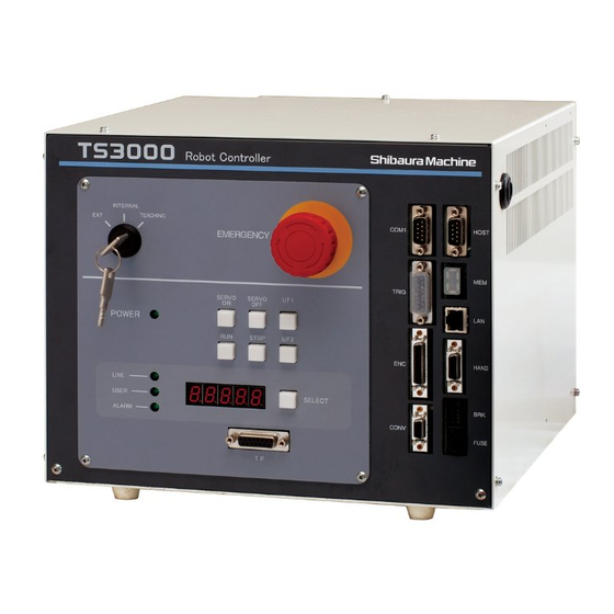
TP3000 OPERATOR S MANUAL series Robot Controller Main Power and Servo Power of the TS3000 Controller 2.2.1 Control Panel (TS3000) The control panel of the TS3000 controller is shown in the figure below. INTERNAL TEACHING EMERGENCY SERVO SERVO POWER STOP LINE USER SELECT... -
Page 47: Turning On The Main Power
TP3000 OPERATOR S MANUAL series Robot Controller ALARM: Alarm number currently generated in the controller. If two (2) or more alarms have occurred, such alarm numbers are displayed at intervals of two (2) seconds. When an alarm occurs, this switch flashes. (7) UF1 &... - Page 48 TP3000 OPERATOR S MANUAL series Robot Controller Goes ON Cautions The following reserved files are required in the RAM drive. MACHINE. PAR SCOL. LIB * EXTRNSEL. PAR* SERVO. PAR AUTOSTR. BAT * ETHERNET. PAR* ROBOT. PAR PALLET. LIB * CONVEYOR. PAR* USER.
-
Page 49: Turning On The Servo Power (Ts3000)
TP3000 OPERATOR S MANUAL series Robot Controller 2.2.3 Turning ON the Servo Power (TS3000) CAUTION If the robot moves abnormally at servo power ON, immediately press the EMERGENCY stop pushbutton switch to turn the servo power off. If you enter the dangerous area of the robot, turn off the servo power beforehand. -
Page 50: Turning Off The Servo Power (Ts3000)
TP3000 OPERATOR S MANUAL series Robot Controller Cautions While the EMERGENCY stop switch is pressed, the servo power will not turn on. Be sure to cancel an emergency stop before turning on the servo power. The servo power can be turned on through the teach pendant only when the TEACHING mode is selected. -
Page 51: Turning Off The Main Power (Ts3000)
TP3000 OPERATOR S MANUAL series Robot Controller Goes ON Cautions DO NOT turn off the servo power while the robot is operating. When you have to stop the robot urgently, press the EMERGENCY stop switch instead. Before you have to enter the robot working area, or when no operator is to be present at other than automatic operation, turn off the servo power for safety reasons. - Page 52 TP3000 OPERATOR S MANUAL series Robot Controller Goes OFF Cautions DO NOT turn off the main power while the servo power is on or during file operation or any other processing. Before turning off the main power, make sure that the servo power is off and that no active processing is present.
-
Page 53: Main Power And Servo Power Of The Tsl3000 Controller
TP3000 OPERATOR S MANUAL series Robot Controller Main Power and Servo Power of the TSL3000 Controller 2.3.1 Front Panel of the Controller (TSL3000) The front panel of the TSL3000 controller is shown in the figure below. (1) Key switch Used to select the master operation mode. (2) POWER Indicates that the main power is ON. -
Page 54: Main Power On (Tsl3000)
TP3000 OPERATOR S MANUAL series Robot Controller 2.3.2 Main Power ON (TSL3000) CAUTION If an abnormality occurs when the main power switch of the controller is turned on or if the POWER LED lamp on the control panel remains off after the main power switch of the controller is turned on, turn off the main power immediately and check the wiring. - Page 55 TP3000 OPERATOR S MANUAL series Robot Controller Caution The following reserved files are required on the RAM drive. MACHINE.PAR SCOL .LIB * EXTRNSEL.PAR* SERVO .PAR AUTOSTR.BAT * ETHERNET.PAR* ROBOT .PAR PALLET .LIB * CONVEYOR.PAR* USER .PAR Files indicated by * are optional. An error will occur only if a function requiring these optional files is executed.
- Page 56 TP3000 OPERATOR S MANUAL series Robot Controller Goes ON Cautions While the EMERGENCY stop switch is pressed, the servo power will not turn on. Be sure to cancel an emergency stop before turning on the servo power. The servo power can be turned on through the teach pendant only when the TEACHING mode is selected.
-
Page 57: Turning Off The Servo Power (Tsl3000)
TP3000 OPERATOR S MANUAL series Robot Controller 2.3.4 Turning OFF the Servo Power (TSL3000) Functional Explanation Turns off the main circuit power of the servo driver. The servo-controlled axes are set free and any brake is activated. Operating Procedure Step 1: Turning off the servo power. In the TEACHING mode, release the Enable switch on the teach pendant. -
Page 58: Turning Off The Main Power (Tsl3000)
TP3000 OPERATOR S MANUAL series Robot Controller 2.3.5 Turning OFF the Main Power (TSL3000) Functional Explanation Turns off the main power and stops controller processing. Operating Procedure Step 1: Turning off the main power. Switch the no fuse breaker installed at the exterior of the controller to the OFF side. The "POWER"... -
Page 59: Teaching Operation
series Robot Controller TP3000 OPERATOR’S MANUAL Section 3 Teaching Operation Selecting the Teaching Mode Functional Explanation Changes over to the TEACHING mode in which the robot is manually guided, points are taught, files are operated and the system is controlled. Operating Procedure Step 1: Teaching mode selection. - Page 60 series Robot Controller TP3000 OPERATOR’S MANUAL Step 2: Calling the JOG key sheet. Lightly grip the Enable switch on the rear panel of the TP3000 teach pendant and open the contact of the Safety switch. While the safety switch contact is open, the key sheet switches to the manual guidance key sheet (JOG key sheet) and the guide coordinates (COORD), guide speed (SPEED) as well as the work coordinate system and tool coordinate system currently being set up are displayed in the upper part of the screen.
-
Page 61: Setting Up The Guide Coordinates
series Robot Controller TP3000 OPERATOR’S MANUAL Setting Up the Guide Coordinates Functional Explanation Sets up the coordinate system to be used during manual guide. You can select from the joint coordinates (JOINT), world coordinates, work coordinates and tool coordinates. Operating Procedure Step 1: Coordinate selection. -
Page 62: Setting Up The Guide Mode
series Robot Controller TP3000 OPERATOR’S MANUAL Setting Up the Guide Mode The guide mode consists of two modes of jog and inching. [Jog Guide] While a guide key is being held down, the robot operates in the direction where the key is being held down (positive or negative direction). -
Page 63: Guide Mode
series Robot Controller TP3000 OPERATOR’S MANUAL Guide Mode Functional Explanation Selects the speed or travel distance for manual guide. When the JOG mode is selected, speed selection becomes effective. When the INCHING mode is selected, travel distance selection prevails. Select the speed or travel distance according to the distance to the target position. When the guide mode is JOG, the SPEED key is used to select the seed. -
Page 64: Guidance
series Robot Controller TP3000 OPERATOR’S MANUAL Guidance CAUTION • When guiding the robot manually, DO NOT enter the dangerous area of the robot. • If the robot moves abnormally, immediately effect an emergency stop. Functional Explanation While the JOG or INCHING mode is selected, the robot can be moved in a desired direction by pressing the appropriate guide key. - Page 65 series Robot Controller TP3000 OPERATOR’S MANUAL Step 2: Guide operation. Lightly hold the Enable switch to turn ON the servo and then press the guide key (a key indicating the axis and direction) of the desired axis. The robot operates on the specified coordinates in the direction of the axis you manipulated.
- Page 66 series Robot Controller TP3000 OPERATOR’S MANUAL Cautions The guide keys are operative only when they are pressed with the servo being turned on. Pressing the Enable switch two levels down completely sets the same state as releasing the Enable switch. ...
-
Page 67: Program Editing
series Robot Controller TP3000 Section 4 Program Editing Starting Up the Program Editor [EDIT] Functional Explanation Starts the program editor. Operating Procedure Step 1: Mode selection. Change over the mode switch equipped on the control panel to "TEACHING". TS3000 TSL3000 Select TEACHING Step 2: Selections in the program editor Press the [EDIT] key on the top key sheet in the TEACHING mode. - Page 68 series Robot Controller TP3000 Step 3: Specify File A list of the program files in the controller is displayed on the screen. To select an existing file, select the desired file with the up and down cursor keys and then press the [EXE] key. The program editor starts.
- Page 69 series Robot Controller TP3000 Related Function The file display sort functions include <display by name>, <display by file creation time> and <file search function>. <Display by name> Press the [NAME] key. The file list is sorted by name. Each time the [NAME] key is pressed, the sorting order changes between ascending order and descending order.
-
Page 70: Structure Of The Program Editor
series Robot Controller TP3000 Cautions If a file with large memory size is specified, it will take a long time until the progress bar is shown and editing is enabled. Please wait until the progress bar disappears. Even if the Master Mode key switch is changed to "TEACHING" during editing, the editing mode does not finish. -
Page 71: Move Cursor
series Robot Controller TP3000 For more information about the operation methods of the [ALPH], [NUM] and [SMBL] keys, please see Section 1. Move Cursor Functional Explanation Moves the cursor by one character in the direction of an arrow key. Operating Procedure Step 1: Cursor operation Among the arrow keys, press the one pointing the direction you want to move the cursor to. -
Page 72: Move Cursor In Word Units
series Robot Controller TP3000 Move Cursor in Word Units Functional Explanation Performs the lateral movement of the cursor in units of words starting with an alphabetic character. Operating Procedure Step 1: Move the cursor in word units. Press the [ ] or [ ] key. The cursor can be moved laterally in units of words starting with an alphabetic character. - Page 73 series Robot Controller TP3000 Step 2: Move the cursor to the beginning of the line. While holding down the [ALT] key, press the move to the beginning-of-line key ([|]). STE 85412...
-
Page 74: Backspace
series Robot Controller TP3000 Step 3: Move the cursor to the end of the line. While holding down the [ALT] key, press the move to the end-of-line key ([|]). Backspace Functional Explanation Deletes one character in front of the cursor. Operating Procedure Step 1: Execution of backspace Press the [BS] key. -
Page 75: Delete
series Robot Controller TP3000 Delete Functional Explanation Deletes one character behind the cursor. Operating Procedure Step 1: Calling the [DEL] key Press the [ALT] key. While the [ALT] key is being held down, the key sheet changes and the [DEL] key is displayed. Step 2: Execution of delete Press the [DEL] key. -
Page 76: Line Feed
series Robot Controller TP3000 Line Feed Functional Explanation Executes a line feed on the PRG EDIT screen. Operating Procedure Step 2: Execution of line feed Move the cursor to the position where you want to perform line feed and then press the [EXE] key. - Page 77 series Robot Controller TP3000 Insert Mode Replace Mode Step 2: Entering text in the insert mode If text is entered in the insert mode, the entered text will be inserted at the cursor position. Step 3: Entering text in the replace mode In the replace mode, the text on which the cursor is being placed will be displayed in reverse video.
-
Page 78: Scroll Screen Vertically
series Robot Controller TP3000 4.11 Scroll Screen Vertically Functional Explanation Moves the cursor across multiple lines vertically. When the cursor moves exceeding the number of lines displayed on the screen, screen scrolling is performed. Operating Procedure Step 1: Calling the vertical screen scroll keys Press the [ALT] key. -
Page 79: Candidate Input Function
series Robot Controller TP3000 Step 3: Scrolling down the screen While holding down the [ALT] key, press the scroll down key. Scroll down the screen. 4.12 Candidate Input Function Functional Explanation Displays the reserved words starting with the entered character string in the candidate Entry window when text is entered. - Page 80 series Robot Controller TP3000 Candidate entry window As text input continues, the content of the candidate entry window is filtered further more. If no candidate exists from the beginning or there are no candidates left, the candidate entry window is not displayed. Step 3: Selecting from candidates Press the up and down cursor keys while the candidate entry window is being displayed.
-
Page 81: Program Hierarchy Display
series Robot Controller TP3000 Step 4: Execution of direct entry Press the [EXE] key. Once direct entry is executed, the candidate entry window closes automatically. Cautions It is not possible to switch to enable or disable the function while the candidate entry window is being displayed. - Page 82 series Robot Controller TP3000 The hierarchy can be opened and closed with the left and right cursor keys. Step 2: Moving to each block from hierarchical display Select the name of the block you want to move from hierarchical display and then press the [EXE] key.
-
Page 83: Move To Beginning Of Program
series Robot Controller TP3000 Step 3: Finishing hierarchical display Press the [ESC] or [OUTLINE] key. 4.14 Move to Beginning of Program Functional Explanation Moves the cursor to the beginning (GLOBAL section) of the program being edited. Operating Procedure Step 1: Moving to the beginning of the program Press the [GLOBAL] key. -
Page 84: Program Edit Functions
series Robot Controller TP3000 4.15 Program Edit Functions The TP3000 has the following program edit functions. A list of these functions is outlined in the table below. Menu Key Icon Description of Operation [COPY] Copies a character string. [CUT] Cuts a character string. Pastes a copied or cut character string to the position [PEST] immediately after the cursor. -
Page 85: Copy
series Robot Controller TP3000 4.15.1 Copy Functional Explanation Copies a character string. Operating Procedure Step 1: Calling the [COPY] key ], [CUT] and [PAST] keys are displayed on the key sheet. Step 2: Setting up the copy range Press the [COPY] key. The display of the [COPY] key changes to the [COPY SET] key. When the cursor is manipulated at this time, the range traced with the cursor is displayed in reverse video. - Page 86 series Robot Controller TP3000 Step 3: Execution of copy After specifying a block of the range you want to copy, press the [COPY SET] or [EXE] key. Related Functions During block specification, the cursor can also be moved in word units and to the end of the line.
-
Page 87: Cut
series Robot Controller TP3000 4.15.2 Cut Functional Explanation Cuts a character string. Operating Procedure Step 1: Calling the [CUT] key The [COPY], [CUT] and [PAST] keys are displayed on the key sheet. Step 2: Setting up the cut range Press the [CUT] key. The display of the [CUT] key changes to the [CUT SET] key. When the cursor is manipulated at this time, the range traced with the cursor is displayed in reverse video. - Page 88 series Robot Controller TP3000 Step 3: Execution of cut After specifying a block of the range you want to cut, press the [CUT SET] or [EXE] key. Related Functions Related Functions During block specification, the cursor can also be moved in word units and to the end of the line.
-
Page 89: Paste
series Robot Controller TP3000 4.15.3 Paste Functional Explanation Pastes a copy or cut character string. Operating Procedure Step 1: Calling the [PAST] key The [COPY], [CUT] and [PAST] keys are displayed on the key sheet. Step 2: Execution of paste Move the cursor to the position where you want to paste to and then press the [PAST] key. -
Page 90: Search
series Robot Controller TP3000 4.15.4 Search Functional Explanation Searches for a character string. If there are search candidate character strings, you can move among the candidates using the up and down cursor keys. Operating Procedure Step 1: Calling the [SRCH] key displayed on the key sheet. - Page 91 series Robot Controller TP3000 After specifying a block of the character string you want to search for, press the [SRCH SET] key. The cursor moves to the command line. * If you are not selecting the character string you want to search for in the program, press the [SRCH] key and then immediately press the [SRCH SET] key.
-
Page 92: Replace
series Robot Controller TP3000 Step 5: Quitting the search function To finish moving search candidates, press a key other than the up and down cursor keys. The cursor appears and the search function finishes. Caution Neither kanji nor kana characters can be searched for in a file containing kanji and kana characters in a program. - Page 93 series Robot Controller TP3000 When the cursor is manipulated at this time, the range traced with the cursor is displayed in reverse video. After specifying a block of the character string you want to search for, press the [CHNG SET] key. The cursor moves to the command line (BEFORE).
- Page 94 series Robot Controller TP3000 * If you are not selecting a replacement candidate in the program, press the [CHNG] key and then immediately press the [CHNG SET] key. Step 3: Extracting a replacement candidate Edit the search character string by editing the command line. Once the character string you want to search has been determined, press the [EXE] key.
- Page 95 series Robot Controller TP3000 Step 6: Execution of replacement To execute the replacement of the replacement candidate, press the [EXE] key. Step 7: Quitting the replace function To finish moving replacement candidates, press a key other than the up and down cursor keys.
-
Page 96: Calling A Subprogram Or Label
series Robot Controller TP3000 Step 2: Calling a subprogram or label Position the cursor on a subprogram name or label in the main program, and then press the [CALL] key. Move the cursor to the beginning of a subprogram or label. Step 3: Returning from a subprogram or label to the calling source Press the [CALL RET] key. -
Page 97: Jump To Specified Line
series Robot Controller TP3000 Caution If the cursor is not positioned on a subprogram name or label, the [CALL] key does not take effect. 4.15.7 Jump to Specified Line Functional Explanation Moves the cursor to the beginning of the specified line. Operating Procedure Step 1: Execution of jump Press the [JUMP] key. -
Page 98: Edit Data
series Robot Controller TP3000 Related Function If a line number exceeding the last line number containing a file is entered, the cursor moves to that last line number. 4.15.8 Edit Data Functional Explanation Starts the data editor. Operating Procedure Step 1: Starting the data editor Press the [DATA] key. -
Page 99: Discard Changes And Quit
series Robot Controller TP3000 Step 2: Execution of save Press the [SAVE] key. A save confirmation message appears on the command line. Next, press the [EXE] key. Save the file to the controller and quit the program editor. If the [ESC] key is pressed while a confirmation message is being displayed, [SAVE] is canceled and program editing can be continued. -
Page 100: Automatic Start File
series Robot Controller TP3000 Step 2: Discards the changes made and quits the program editor. Press the [NO SAVE] key. A no-save confirmation message appears on the command line. Press the [EXE] key. Discard the changes made and quits the program editor. If the [ESC] key is pressed while a confirmation message is being displayed, [NO SAVE] is canceled and program editing can be continued. - Page 101 series Robot Controller TP3000 DATE : Displays the day. TIME : Displays the time. SVON : Servo ON command : Program RUN command The SVON command takes effect when the mode of the controller is the internal automatic (INTERNAL) mode or external automatic (EXT) mode. Step 3: Quitting the program editor Press the [SAVE] key and quits the program editor.
-
Page 102: Data Editing
series Robot Controller TP3000 Section 5 Data Editing The data editing function allows input and editing of positional data, coordinate data and load data. Each data is saved in a file together with a program, and can be edited on the file basis. - Page 103 series Robot Controller TP3000 Step 2: Selecting the data editor Press the [EDIT] key on the top key sheet in the TEACHING mode. The key sheet and screen displays change, and the [PRG EDIT], [DATA EDIT] and [PAR EDIT] keys appear.
- Page 104 series Robot Controller TP3000 Related Functions The file display sort functions include <display by name>, <display by file creation time> and <file search function>. <Display by name> Press the [NAME] key. The file list is sorted by name. Each time the [NAME] key is pressed, the sorting order changes between ascending order and descending order.
-
Page 105: Configuration Of The Data Editor
series Robot Controller TP3000 Cautions If a file with large memory size is specified, it will take a long time until the progress bar is shown and editing is enabled. Please wait until the progress bar disappears. Even if the Master Mode key switch is changed to "TEACHING" during editing, the editing mode does not finish. -
Page 106: Basic Operations Of The Data Editor
series Robot Controller TP3000 Basic Operations of the Data Editor 5.3.1 Add New Data Functional Explanation Adds new position data, coordinate data, and load data. Operating Procedure Step 1: Adding new data Press the [INS](insert line) key. The cursor moves to the command line. Step 2: Entering a new data name Enter a data name on the command line, and press the [EXE] key. -
Page 107: Edit Various Elements
series Robot Controller TP3000 Cautions The position data name can consist of up to 10 characters. When entering a name on the command line, if "(" is not entered within the first eight characters, no more than eight characters can be entered. ... -
Page 108: Delete Various Elements
series Robot Controller TP3000 Step 2: Entering data Edit a value on the command line. Press the [EXE] key. The edited value is reflected in the data. The cursor returns to the data table. The cursor automatically moves to the next item. 5.3.3 Delete Various Elements Functional Explanation... -
Page 109: Move Cursor
series Robot Controller TP3000 Step 2: Execution of deletion While holding down the [ALT] key, press the position data delete key. The line on which the editing is focused is deleted. Cautions If coordinate data is deleted, all the position data which has been added to the coordinate data will also be deleted. -
Page 110: 3-Element Scroll
series Robot Controller TP3000 Operating Procedure Step 1: Moving the cursor Press any of the horizontal and vertical arrow keys. The cursor moves to an adjacent cell. 5.3.5 3-Element Scroll Functional Explanation Horizontal scrolling of 3 elements can be performed while a data list is being displayed. Operating Procedure Step 1: 3-element scroll Press one of the double arrow keys. -
Page 111: Move To End-Of-Line Cell
series Robot Controller TP3000 5.3.6 Move to End-of-Line Cell Functional Explanation The cursor moves to the end of the line of a data element. Operating Procedure Step 1: Calling the arrow keys to move to the end of the line Press the [ALT] key. -
Page 112: Scroll Screen Vertically
series Robot Controller TP3000 Caution To move the cursor to the NAME cell, press the left arrow key at the position of element X. 5.3.7 Scroll Screen Vertically Functional Explanation Scrolls the screen vertically. Operating Procedure Step 1: Calling the vertical screen scroll keys Press the [ALT] key. -
Page 113: Position Data Editing
series Robot Controller TP3000 Position Data Editing 5.4.1 Position Data List Display Functional Explanation Displays the position data of each coordinate on a single line. From the position data list display, position data can be added, deleted and edited. The position data displayed immediately after starting the data editor is the position data on the world coordinates. - Page 114 series Robot Controller TP3000 Indicates the position data on the world coordinates. Elements in list display are arranged in the following order. Data name Element X: X-axis Element C: Rotation angle coordinate around the Z axis Element Y: Y-axis Element T: Expanding axis coordinate Element Z: Z-axis CONFIG: Configuration and...
-
Page 115: Editing Form Data
series Robot Controller TP3000 5.4.2 Editing Form Data Functional Explanation Edits the CONFIG (configuration) data of each joint. Operating Procedure Step 1: Editing CONFIG data Position the cursor on a CONFIG data cell and press the [EXE] key, or press the [CONFIG] key on the key sheet. -
Page 116: Adding Position Data To Coordinate Data
series Robot Controller TP3000 Step 2: Editing each joint Press any of the CONFIG edit keys of the joint you want to change. Each time the key is pressed, the CONFIG data switches. Changes to CONFIG data is executed and reflected at the timing when these keys are pressed. - Page 117 series Robot Controller TP3000 Step 2: Selecting a coordinate system Select coordinate data with the up and down keys, and press the [EXE] key. The selected coordinate data name appears in the upper left of the screen. Step 3: Adding position data Press the [INS] key and add position data.
-
Page 118: Teaching Position Data
series Robot Controller TP3000 5.4.4 Teaching Position Data CAUTION In principle, the teaching operation should be performed outside the dangerous area of the robot. If it must be performed inevitably within the dangerous area, strictly observe the following matters. (1) The teaching operation should always be performed by two (2) persons. One person performs the job and the other person watches outside the dangerous area. - Page 119 series Robot Controller TP3000 Functional Explanation Guide the tool tip of the robot to a teach point, and then register (overwrite) the current position of the robot to the position data where the cursor is positioned. Operating Procedure Step 1: Calling the [TEACH] key Lightly grip the Enable switch when editing position data in order to open the contact of the Safety switch.
- Page 120 series Robot Controller TP3000 When the [TEACH] key is pressed, a confirmation message appears on the command line. To execute teaching, press the [EXE] key. When the current position and the position data of the point currently being selected match, the current position display is highlighted in reverse video. To cancel teaching, press the [ESC] key.
-
Page 121: Moving To Teach Point
series Robot Controller TP3000 5.4.5 Moving to Teach Point Functional Explanation Moves the robot position to the position data pointed by the cursor in synchronous operation. Operating Procedure Step 1: Calling the [M-TO] key Lightly grip the Enable switch when editing position data in order to open the contact of the Safety switch. -
Page 122: Move To Teach Point Function [Bypas]
series Robot Controller TP3000 Step 3: Starting to move to a teach point In the servo ON state, keep holding down the [MOVE] key. The robot moves toward the teach point while performing synchronous operation. When the [MOVE] key is released, movement to the teach point stops. - Page 123 series Robot Controller TP3000 Preparation In order to use the bypass function, it is necessary to enable the bypass function and set the bypass distance in the Z-axis direction in [U23] Bypass function parameter of the user parameter file in advance. The meanings of the user parameters and sample settings are shown below.
- Page 124 series Robot Controller TP3000 Z axis offset parameter (parameter dedicated to the LCDR) { Z Axis offset parameter } = 0.0 0.0 This is a parameter dedicated to the LCDR (glass transport robot). It is not used by SCARA robots, When parameter editing is finished, save the file and then turn the power to the controller off/on.
- Page 125 series Robot Controller TP3000 Step 3: Starting bypass movement In the servo ON state, keep holding down the [MOVE] key. The robot moves toward the teach point while performing bypass operation. As shown in the figure below, the robot operates (P0)→(P0a)→(P1b)→(P1). When the [MOVE] key is released, movement to the teach point stops.
-
Page 126: Detailed Position Data Display
series Robot Controller TP3000 5.4.7 Detailed Position Data Display Functional Explanation The detailed positional data display mode displays one positional data element on the full screen. In this mode, position data can be added, deleted and edited. Operating Procedure Step 1: Switching detailed position data display Press the [DIR/FULL] key. -
Page 127: Coordinate Data Editing
series Robot Controller TP3000 Coordinate Data Editing 5.5.1 Coordinate Data List Display Functional Explanation Displays coordinate data in a list. Coordinate data is classified into work coordinates and tool coordinates in terms of usage. Whether coordinate data added in this operation will be used as work coordinates or tool coordinates needs to be determined by the user. -
Page 128: Setting Up And Clearing Work Coordinates
series Robot Controller TP3000 Step 2: Using coordinate data as the work coordinate system When using coordinate data as the work coordinate system, enter setting values in elements as if viewed from the world coordinate system. Teaching can be performed to the work coordinate system using functions such as in Section 5.5.4, "Coordinate Data 1-Point Teaching", Section 5.5.5, "Coordinate Data 2-Point Teaching (SCARA), and Section 5.5.6, "Coordinate Data 3-Point Teaching (6 axes). - Page 129 series Robot Controller TP3000 Step 2: Setting Up and Clearing Work Coordinates Position the cursor on the coordinate data you want to use as work coordinates, and press the [WORK] key. The selected coordinate name appears in the work coordinate display field on the screen.
-
Page 130: Selecting And Clearing Tool Coordinates
series Robot Controller TP3000 Cautions When coordinates are selected during position data editing, these coordinates will automatically be set as work coordinates. The work coordinates which have been set up are maintained regardless of the execution of [SAVE] or [NO SAVE] to files. ... - Page 131 series Robot Controller TP3000 Step 2: Setting up the tool coordinates Position the cursor on the coordinate data you want to use as tool coordinates, and press the [TOOL] key. The selected coordinate name appears in the tool coordinate display field on the screen.
-
Page 132: Coordinate Data 1-Point Teaching
series Robot Controller TP3000 Once set up, the tool coordinates will not be cleared until the tool coordinates are cleared (see the next item) or a program is selected in the test operation mode. 5.5.4 Coordinate Data 1-Point Teaching CAUTION In principle, the teaching operation should be performed outside the dangerous area of the robot. - Page 133 series Robot Controller TP3000 1TEACH key Enable switch Step 2: Selecting the bypass function Select the coordinate data you want to teach by moving the cursor up and down, and press the [1TEACH] key. The "1PNT>>Coordinate" message appears on the command line. Step 3: Execution of 1-point teaching Guiding manually, move the tool tip of the robot to the coordinate position you want to teach, and press the [EXE] key.
- Page 134 series Robot Controller TP3000 To cancel teaching halfway, press the [ESC] key. Step 4: Returning to data editing Release the Enable switch or press the [ESC] key. The data editor returns to the editing of coordinate data. Related Function Teaching can also be performed with the [1TEACH] key on the Edit Function menu which is displayed on the key sheet during coordinate data editing.
-
Page 135: Coordinate Data 2-Point Teaching
series Robot Controller TP3000 5.5.5 Coordinate Data 2-Point Teaching CAUTION In principle, the teaching operation should be performed outside the dangerous area of the robot. If it must be performed inevitably within the dangerous area, strictly observe the following matters. (1) The teaching operation should always be performed by two (2) persons. - Page 136 series Robot Controller TP3000 2TEACH key Enable switch Step 2: Selecting the 2-point teach function Select the coordinate data you want to teach by moving the cursor up and down, and press the [2TEACH] key. The "2PNT>>Origin" message appears on the command line. Step 3: Execution of teaching (Origin) Guiding manually, move the tool tip of the robot to the position you want to set as the origin of the coordinates.
- Page 137 series Robot Controller TP3000 Step 4: Execution of teaching (Direction) Guiding manually, move the tool tip of the robot to the point where you want to set as the direction (positive X direction) of the coordinates. Once the position has been determined, press the [EXE] key.
-
Page 138: Detailed Coordinate Data Display
series Robot Controller TP3000 Step 5: Returning to data editing Release the Enable switch or press the [ESC] key. The data editor returns to the editing of coordinate data. Related Function Teaching can also be performed with the [2TEACH] key on the Edit Function menu which is displayed on the key sheet during coordinate data editing. -
Page 139: Load Data Editing
series Robot Controller TP3000 DIR Display FULL Display Cautions The procedures to add, delete and edit coordinate data in the detailed coordinate data display mode are the same as those in the coordinate data list display mode. The "3-element scroll", "move to end of line" and "vertical screen scroll" operations do not take effect in the detailed coordinate data display mode. -
Page 140: Detailed Load Data Display
series Robot Controller TP3000 Elements in list display are arranged in the following order. Data name Weight Center of gravity (kg) offset (mm) Caution The basic operations of adding, editing and deleting load data are the same as those in position data editing. 5.6.2 Detailed Load Data Display Functional Explanation... - Page 141 series Robot Controller TP3000 DIR Display FULL Display Cautions The procedures to add, delete and edit load data in the detailed load data display mode are the same as those in the load data list display mode. The "3-element scroll", "move to end of line" and "vertical screen scroll" operations do not take effect in the detailed load data display mode.
-
Page 142: Data Editing Functions
series Robot Controller TP3000 Data Editing Functions The editing functions common to position data, coordinate data and load data are outlined in the table below. Menu Key Icon Description of Operation Inserts lines with specified names by [INS NAME] assigning sequential numbers when adding lines. -
Page 143: Insert Sequential Lines
series Robot Controller TP3000 5.7.1 Insert Sequential Lines Functional Explanation Inserts lines by assigning sequential numbers according to the name registered in the base name field. Operating Procedure Step 1: Registering the base name Press the [NAME] key. Enter the base name when entering sequentially numbered lines on the command line. Once the base name has been determined, press the [EXE] key. - Page 144 series Robot Controller TP3000 Base name Step 2: Execution of sequentially numbered line insertion Press the [INS] key. Each time the [INS] key is pressed, a line having a name consisting of the base name and a sequential number is added. Step 3: Clearing the insertion of sequentially numbered lines To return the insertion of sequentially numbered lines back to regular line insertion, press the [NAME] key again and delete the NAME field to make it blank.
-
Page 145: Copy
series Robot Controller TP3000 Cautions If data to be added by sequentially numbered line insertion already exists, sequential numbers will be assigned beginning with its maximum value. The base name for sequentially numbered line insertion can be set individually for position data, coordinate data, and load data. -
Page 146: Cut
series Robot Controller TP3000 Step 2: Execution of copy Position the cursor on the numeric value you want to copy, and press the [COPY] key. Cautions Data names cannot be copied. Copies crossing over different data types (POINT, TRANS, PYLD) cannot be performed. - Page 147 series Robot Controller TP3000 Step 2: Setting up the cut range Press the [CUT] key. The display of the [CUT] key changes to the [CUT SET] key. The elements on the line on which the cursor is positioned are all highlighted in reverse video.
-
Page 148: Paste
series Robot Controller TP3000 Cautions The position data belonging to each coordinate will all be deleted. World coordinates cannot be selected. (They cannot be deleted.) 5.7.4 Paste Functional Explanation Pastes data on a multiple number of copied or cut lines. Operating Procedure Step 1: Calling the [PAST] key The [COPY], [CUT] and [PAST] keys are displayed on the key sheet. - Page 149 series Robot Controller TP3000 Step 3: Execution of pasting cut data Press the [PAST] key. The line you have cut is inserted under the line on which the cursor is positioned. STE 85412 5-48...
-
Page 150: Search
series Robot Controller TP3000 5.7.5 Search Functional Explanation Searches for character strings corresponding to position data names, coordinate data names, and load data names. Operating Procedure Step 1: Calling the [SRCH] key Press the key sheet. Step 2: Specifying a search character string Press the [SRCH] key. -
Page 151: Character String Filter
series Robot Controller TP3000 Cautions If search is performed in the character string filtering function, search will only be performed to a group of data whose display is restricted with a character string filter. If no search name is found, the message "NOT FOUND" is displayed on the command line, and the function is closed. - Page 152 series Robot Controller TP3000 Step 2: Entering a filtering character string Press the [FILT] key. Enter a filtering character string on the command line. Step 3: Execution of character string filtering Once the filtering character string has been determined, press the [EXE] key. Only the data starting with the filtering character string is displayed.
- Page 153 series Robot Controller TP3000 Caution If data that is not applicable to the display is newly added during the execution of character string filtering, character string filtering will be canceled. 5.7.7 Table Sorting Functional Explanation Sorts data in a table in ascending or descending order. Operating Procedure Step 1: Calling the [SORT] key Press the...
-
Page 154: Program Editing
series Robot Controller TP3000 Caution Table sorting is performed to data hidden by a character string filter. 5.7.8 Program Editing Functional Explanation Starts the program editor. Operating Procedure Step 1: Starting the program editor Press the [PRG→] key and start the program editor. For details on program editing, please see Section 4, "Program Editing". -
Page 155: Save And Quit
series Robot Controller TP3000 5.7.9 Save and Quit Functional Explanation Saves data and quits the program editor. Operating Procedure Step 1: Calling the [SAVE] key Press the [FILE] key. The [SAVE] and [NO SAVE] keys are displayed on the key sheet. Step 2: Execution of save Press the [SAVE] key. -
Page 156: Discard Changes And Quit
series Robot Controller TP3000 5.7.10 Discard Changes and Quit Functional Explanation Discards edited data and quits the program editor. Operating Procedure Step 1: Calling the [NO SAVE] key Press the [FILE] key. The [SAVE] and [NO SAVE] keys are displayed on the key sheet. Step 2: Discarding edited data and quitting the program editor Press the [NO SAVE] key. -
Page 157: Parameter Editing
TP3000 series Robot Controller Section 6 Parameter Editing The parameter editing function edits the parameter files inside the controller. After editing the parameter files, turn the power to the controller on/off in order to make the changes effective. Starting the Parameter Editor Functional Explanation Starts the parameter editor. - Page 158 TP3000 series Robot Controller Step 2: Selecting the parameter editor Press the [EDIT] key on the top key sheet in the TEACHING mode. The key sheet and screen displays change, and the [PRG EDIT], [DATA EDIT] and [PAR EDIT] keys appear. Next, press the [DATA EDIT] key.
- Page 159 TP3000 series Robot Controller <Display by file creation time> Press the [TIME] key. The file list is sorted by file creation time. Each time the [TIME] key is pressed, the sorting order changes between ascending order and descending order. <File search function> Press the [INPUT] key.
-
Page 160: Overview Of The Parameter Editor
TP3000 series Robot Controller Overview of the Parameter Editor The screen structure of the parameter editor is shown below. Parameter Editor Screen and Key Sheet Description of Display ① Data editing screen ② Displays the name of the file being selected. ③... -
Page 161: Move Cursor
TP3000 series Robot Controller Move Cursor Functional Explanation When the cursor is manipulated, the cursor moves only to the applicable editing area. Operating Procedure Step 1: Cursor operation Press the arrow key pointing the direction you want to move the cursor to. The cursor moves to the applicable editing area. -
Page 162: Horizontal Scroll
TP3000 series Robot Controller Horizontal Scroll Functional Explanation Scrolls the screen horizontally. Operating Procedure Step 1: Cursor operation Press the [<<] or [>>] key. The screen scrolls horizontally. Editing Parameter Elements Functional Explanation Edit parameter elements. STE 85412... - Page 163 TP3000 series Robot Controller Operating Procedure Step 1: Starting to edit Select the parameter element you want to edit with the cursor, and then press the [EXE] key. Edit the parameter element on the command line. Step 2: Reflecting changes made Once the changes have been determined, press the [EXE] key.
-
Page 164: Parameter Editing Function
TP3000 series Robot Controller To abort, press the [ESC] key. Parameter Editing Function The editing functions of the parameter editor are outlined in the table below. Menu Key Icon Description of Operation Searches the specified character [SRCH] string. Moves the cursor to the beginning of [JUMP] the specified line. - Page 165 TP3000 series Robot Controller The specified character string is searched from the beginning of the file being edited, and the cursor moves to the beginning of the first line where the specified character string exists. If no search candidate is found, the function is canceled. Caution ...
- Page 166 TP3000 series Robot Controller Caution If a line number exceeding the last line number containing a file is entered, the cursor moves to that last line number. 6.6.3 Save and Quit Functional Explanation Saves the program data and quits the parameter editor. Operating Procedure Step 1: Execution of save Press the [SAVE] key.
- Page 167 TP3000 series Robot Controller Press the [EXE] key. Discards the changes made and quit the parameter editor. If the [ESC] key is pressed while a confirmation message is being displayed, [NO SAVE] is canceled and parameter editing can be continued. STE 85412 6-11...
-
Page 168: Test Operation
series Robot Controller TP3000 Section 7 Test Operation DANGER NEVER enter the dangerous area of the robot during automatic operation. If you still have to enter the dangerous area, be sure to terminate the automatic operation and turn the servo power off beforehand. CAUTION 1. -
Page 169: Selecting Internal Automatic Operation Mode
series Robot Controller TP3000 Selecting Internal Automatic Operation Mode The functions that can be used in the test operation are listed in the table below. Functional Explanation Step 1: Selection of internal automatic mode. Set the master mode switch on the controller panel to "TEACHING". TS3000 TSL3000 Select TEACHING... - Page 170 series Robot Controller TP3000 Step 2: Selecting a test operation mode The screen and key sheet in the TEACHING mode are shown below. Test Operation Mode Screen and Key Sheet Description of Display ① Displays the mode of the controller. TEACHING: Test operation mode ②...
-
Page 171: File Selection
series Robot Controller TP3000 File Selection Functional Explanation Select a file (or program) to be executed. Operating Procedure Step 1: Displaying files Press the [SEL] key. A list of the program files in the controller is displayed. [SEL] Screen and Key Sheet Description of Display ①... - Page 172 series Robot Controller TP3000 Step 2: Selecting a file Select a file with the up and down cursor keys, and then press the [EXE] key. When an execution file is selected, its file name appears in the SEL field on the screen. Related Function The file display sort functions include <display by name>, <display by file creation time>...
-
Page 173: Selecting Run Mode
series Robot Controller TP3000 Cautions Once the execution file has been selected, it remains effective until another file is selected. If a compile error has occurred, however, selection of the execution file is canceled. To reset the execution environment without changing the execution file, execute [RESET] and [PROG]. -
Page 174: Speed Override
series Robot Controller TP3000 Cautions The run mode can be selected even while the program is being executed. The selected run mode also takes effect in test operation and external automatic operation. The selected run mode remains valid until another run mode is selected. ... - Page 175 series Robot Controller TP3000 Step 2: Entering the speed override rate Press one of the [5], [10], [15], [20] and [25] keys on the keyboard. The value of the key you pressed is copied to the command line, and the key sheet changes to number input. A fine value can be set on the command line.
- Page 176 series Robot Controller TP3000 Step 3: Execution of changing of the speed override rate Press the [EXE] key. When changing of the speed override rate is executed, the changed override rate is displayed in the OVRD field on the status bar at the bottom of the screen. Caution ...
-
Page 177: Step Execution
series Robot Controller TP3000 Step Execution Functional Explanation Starts a test operation in the Step mode where the program stops on a per-instruction basis. Step 1: Calling the Mode Setting keys Press the [MODE] key. The [CONT], [CYCLE], [SEG] and [STEP] keys are displayed on the keyboard. - Page 178 series Robot Controller TP3000 Step 3: Step execution Press the [RUN] key in the Servo ON state. After the program is executed for one instruction, it stops. The [STOP] key of the TP3000 switches to the [RUN] key, and the operation to wait for the next step (waiting for the [RUN] key) is activated.
-
Page 179: Startup [Run]
series Robot Controller TP3000 Startup [RUN] Functional Explanation Starts a test operation under the predetermined conditions. It is used for program verification operation. It is also used for resuming an operation after the stop. Operating Procedure Step 1: Setting of running conditions. Set the conditions for executing the file selection, run mode selection speed override setting. - Page 180 series Robot Controller TP3000 Step 3: Execution of RUN Press the [RUN] key on the key sheet. When the [RUN] key is pressed, the key sheet changes to the top key sheet of the TEACHING mode. JOG Key Sheet TEACHING Mode Top Key Sheet Press the EXE key.
-
Page 181: Stop
series Robot Controller TP3000 Cautions The RUN switch equipped on the control panel and "startup command" external control signal are inoperative in the test operation mode. To execute a program from the top, execute [RESET] and [PROG] followed by [RUN]. Stop 7.7.1 CYCLE Stop... -
Page 182: Stop
series Robot Controller TP3000 When the program has been executed to the end, the automatic operation stops at the same time that the RUN switch LED on the control panel goes out and the STOP switch LED goes on. Also, the display of the [STOP] key on the teach pendant changes to the [RUN] key. - Page 183 series Robot Controller TP3000 Operating Procedures Step 1: Stop execution Press the STOP switch in the case of the controller panel. Then the STOP switch LED on the control panel goes on, and when the execution of the instruction currently being executed is completed, the automatic operation stops. When automatic operation is stopped, the RUN switch LED on the control panel goes off.
-
Page 184: Break
series Robot Controller TP3000 7.7.3 BREAK Functional Explanation Immediately decelerates and stops the robot, and stops an automatic operation. This function is used to interrupt the automatic operation. Operating Procedures Step 1: Entering BREAK Press the [BREAK] key. The robot in operation immediately decelerates and stops, and the automatic operation stops. -
Page 185: Emergency Stop
series Robot Controller TP3000 Operating Procedures Step 1: Entering FEED HOLD Press the [FEED HOLD] key. If the robot is in operation, it decelerates and stops. When the robot has stopped, the RUN switch LED on the control panel goes out and the STOP switch LED goes on. -
Page 186: Reset
series Robot Controller TP3000 Operating Procedures Press the EMERGENCY stop pushbutton switch equipped on the control panel or teach pendant, or use the "emergency stop" external control signal. The servo power is turned off and the SERVO ON switch LED on the control panel goes out and the SERVO OFF switch LED goes on. -
Page 187: Program Reset
series Robot Controller TP3000 Operating Procedure Step 1: Calling the various reset keys Press the [RESET] key. The [PROG], [CYCLE], [STEP], [SIG] and [SEL keys are displayed on the key sheet. 7.8.1 Program Reset Functional Explanation Resets all execution conditions (execution steps, variables) for a current file and allows execution of that program from the top. -
Page 188: Step Reset
series Robot Controller TP3000 7.8.2 Step Reset Functional Explanation Resets all execution conditions (excluding variables) for a current file and allows execution of that program from the top. This function is useful to set the repetitive counts in a variable and execute the remaining counts. -
Page 189: Output Signal Reset
series Robot Controller TP3000 Step 2: Execution of cycle reset To reset, press the [EXE] key in succession. To cancel reset, press the [ESC] key. Cautions Use label RCYCLE in a desired step of the main program. Also, specify the GOTO RCYCLE command just before the END command so that the END command of the main program will not be executed. -
Page 190: Execution Line Display [Ldisp]
series Robot Controller TP3000 Operating Procedure Step 1: Selecting execution file reset Press the [SEL] key. Step 2: Execution of execution file reset Press the [SEL] key. The execution file is reset, and the SELECT field in the upper right of the screen is emptied. - Page 191 series Robot Controller TP3000 [LDISP] Screen and Key Sheet Description of Display ① Displays the execution program. Step 2: Asynchronous display of the execution line Press the [SCRLL] key. The synchronization between the execution line and screen scroll is cleared, and the screen can now be scrolled using the up and down cursor keys.
-
Page 192: Variable Monitor [Watch]
series Robot Controller TP3000 Step 4: Returning to execution line display (synchronization) Press the [CURRE] key. Screen scroll synchronizes according to the execution line. Cautions RUN, STOP and BREAK operations can be performed even during execution line display. 7.10 Variable Monitor [WATCH] Functional Explanation Displays the values of a desired global variable. - Page 193 series Robot Controller TP3000 [WATCH] Screen and Key Sheet Description of Display ① Enter the global variable names you want to reference. ② The values of global variables are displayed. STE 85412 7-26...
- Page 194 series Robot Controller TP3000 Step 2: Registering global variables Press the [EXE] key on the desired NAME cell. The command line appears to allow you to enter a global variable name. Once the variable name you want to monitor has been determined, press the [EXE] key. The current variable value is displayed according to the variable type.
- Page 195 series Robot Controller TP3000 ● Coordinate variable display ● Load variable display Step 3: Changing a variable value [CHG] Program values can be changed temporarily. Position the cursor on a variable value, and press the [CHG] key. Change the value on the command line, and execute to overwrite the value by pressing the [EXE] key.
-
Page 196: Direct Execution [Do]
series Robot Controller TP3000 Step 4: Changing a variable value [CHG REST] Overwrite the program file values. Position the cursor on a variable value, and press the [CHG REST] key. (The value input procedure is the same as that in Step 3.) Cautions ... - Page 197 series Robot Controller TP3000 Direct Execution Screen and Key Sheet Description of Display ① Command line for direct execution Step 2: Entering an SCOL program Using the [NUM], [ALPH], [SYMBOL] and other keys, enter an SCOL program on the command line. STE 85412 7-30...
- Page 198 series Robot Controller TP3000 Also, by pressing the [MOVEA] or [DOUT] key, a character string can be copied onto the command line. Step 3: Execution of the program While the SCOL program is being entered on the command line, turn on the servo, and then press the [EXE] key in succession.
-
Page 199: Internal Automatic Operation
series Robot Controller TP3000 OPERATOR S MANUAL Section 8 Internal Automatic Operation The internal automatic operation is a function of the TS3000 robot controller. The internal automatic operation function is not supported for the TSL3000. DANGER NEVER enter the dangerous area of the robot during automatic operation. If you still have to enter the dangerous area, be sure to terminate the automatic operation and turn the servo power off beforehand. -
Page 200: Selecting Internal Automatic Operation Mode
series Robot Controller TP3000 OPERATOR S MANUAL Selecting Internal Automatic Operation Mode Selects the internal automatic mode where you can execute a program by a start command given through the control panel. Operating Procedure Step 1: Selection of internal automatic mode. Change over the master mode switch on the control panel to "INTERNAL"... - Page 201 series Robot Controller TP3000 OPERATOR S MANUAL The screen and key sheet when the internal automatic mode is being selected are shown below. Internal Automatic Mode Screen and Key Sheet Description of Display ① Displays the mode of the controller. INTERNAL: Internal operation mode ②...
-
Page 202: Start [Run]
series Robot Controller TP3000 OPERATOR S MANUAL Start [RUN] Functional Explanation Starts an automatic operation under the predetermined conditions. While in the internal automatic operation mode, it is not possible to execute [RUN] from the teach pendant Operating Procedure Step 1: Selecting step execution Set the running conditions for file selection, run mode selection, and speed override. -
Page 203: Speed Override
series Robot Controller TP3000 OPERATOR S MANUAL Caution The "startup command" external control signal is inoperative in the internal automatic operation mode. While in the internal automatic operation mode, it is not possible to execute [RUN] from the teach pendant Speed Override Functional Explanation Sets the speed override for automatic operation. -
Page 204: External Automatic Operation
series Robot Controller TP3000 OPERATOR S MANUAL Section 9 External Automatic Operation DANGER NEVER enter the dangerous area of the robot during automatic operation. If you still have to enter the dangerous area, be sure to terminate the automatic operation and turn the servo power off beforehand. -
Page 205: Selecting External Automatic Operation Mode
series Robot Controller TP3000 OPERATOR S MANUAL Selecting External Automatic Operation Mode Functional Explanation Selects the external automatic mode where you can execute a program by external control signals or commands given from the host computer. Operating Procedure Step 1: Selection of external automatic mode. Change over the master mode switch on the control panel to TS3000 TSL3000... - Page 206 series Robot Controller TP3000 OPERATOR S MANUAL * Regarding the TSL3000 controller, the speed override can be set from the teach pendant in the external automatic operation mode. The screen and key sheet of the TP3000 when the external automatic operation mode is being selected are outlined in the table below.
-
Page 207: Selecting File
series Robot Controller TP3000 OPERATOR S MANUAL Cautions For the functions and use of the external control signals, see the Interface Manual. For the data communication function with the host computer, see the Communication Manual. In the external automatic mode, only the MODE select switch, STOP switch, SERVO ON switch, SERVO OFF switch and EMERGENCY stop pushbutton switch provided on the control panel are operative. -
Page 208: Selecting Run Mode
series Robot Controller TP3000 OPERATOR S MANUAL (d) File selection via data transmission. A file can be selected by data transmission in either "EX. 232C" or "EX. ETHER" mode. For details, see the Communication Manual. When the execution file is selected, the following display appears on the screen. Cautions ... -
Page 209: Speed Override
series Robot Controller TP3000 OPERATOR S MANUAL Cautions In the external control signal mode, the run mode is selected by the cycle operation mode signal. In the "EX. 232C" mode and "EX. ETHER" mode, the cycle operation mode signal is ineffective. When in the "EX. -
Page 210: Startup
series Robot Controller TP3000 OPERATOR S MANUAL Startup Functional Explanation Starts an automatic operation under the predetermined conditions. Operating Procedure (a) Startup by using the start signal in the external signal mode: Input the start signal. For the start signal, see the Interface Manual. (b) Starting via data communication When in the "EX. -
Page 211: Stop
series Robot Controller TP3000 OPERATOR S MANUAL Cautions In the external control signal mode, the cycle operation mode is selected by the input of "cycle operation mode" signal. When the program has been executed to the end in the cycle operation mode, the automatic operation stops with the "cycle end"... -
Page 212: Break
series Robot Controller TP3000 OPERATOR S MANUAL (On the TS3000, the STOP LED on the front panel of the controller goes on when STOP is input.) When automatic operation stops, the RUN LED on the front panel of the controller goes off. -
Page 213: Feed Hold
series Robot Controller TP3000 OPERATOR S MANUAL Caution To restart the operation after the stop by the BREAK command, perform the startup operation. 9.6.4 FEED HOLD Functional Explanation Holds robot motion and program execution. When this function is specified during robot operation, the robot immediately slows down and stops. -
Page 214: Emergency Stop
series Robot Controller TP3000 OPERATOR S MANUAL (On the TS3000, when FEED HOLD is cleared, the STOP LED on the front of the controller goes off.) When execution is restarted, the execution status of the teach pendant changes to "RUN". Cautions If the feed hold is commanded during program execution, program execution can be restarted by canceling the feed hold. -
Page 215: Reset
series Robot Controller TP3000 OPERATOR S MANUAL While the EMERGENCY stop switch is ON, the servo power cannot be turned on. Reset Functional Explanation (1-1) Program reset Resets all execution conditions (execution steps, variables) for a current file and allows execution of that program from the top. - Page 216 series Robot Controller TP3000 OPERATOR S MANUAL In the host mode, reset by external control signal is not possible. For details, see the Communication Manual. Cautions In the program reset mode, all variables used in the program are reset. If you do not wish to reset the variables, use the step reset function instead.
-
Page 217: Section 10 File Operation
series Robot Controller TP3000 OPERATOR S MANUAL Section 10 File Operation With the File Operation function, it is possible to display, copy, delete and rename files in the RAM drive and the USB drive (inside a TS3000 folder). Files can be copied between RAM and USB drives. 10.1 Calling the File Operation Function Functional Explanation Calls the File Operation function. - Page 218 series Robot Controller TP3000 OPERATOR S MANUAL File Operation Screen and Key Sheet Description of Display ① Displays the drive. ② Displays file names. ③ Displays file sizes. ④ Displays dates of creation. ⑤ Displays the number of files. Caution ...
-
Page 219: File List Display
series Robot Controller TP3000 OPERATOR S MANUAL 10.2 File List Display Functional Explanation Displays a list of files registered in the RAM drive or USB drive (TS3000 folder). Operating Procedure Step 1: Displaying files in RAM Press the [FILE] key on the top screen in the TEACHING mode (Section 10.1). A list of files registered in the RAM drives displayed. - Page 220 series Robot Controller TP3000 OPERATOR S MANUAL Related Functions The file list sort functions include <display by name>, <display by file creation time> and <file search function>. <Display by name> Press the [NAME] key. The file list is sorted by name. Each time the [NAME] key is pressed, the sorting order changes between ascending order and descending order.
-
Page 221: File Copy
series Robot Controller TP3000 OPERATOR S MANUAL Caution If the "TS3000" folder (directory) does not exist when the USB drive is selected in each operation, the error message "USB not found" appears and any succeeding operation for the USB drive is disabled. If there is no TS3000 folder (directory) in the USB drive, create one. - Page 222 series Robot Controller TP3000 OPERATOR S MANUAL Step 3: Execution of copy Once the file name has been determined, press the [EXE] key. Copy is executed and the file is copied to the same directory (from RAM to RAM, from USB to USB) as that of the original file.
-
Page 223: File Delete
series Robot Controller TP3000 OPERATOR S MANUAL If the copied file size exceeds the capacity of the RAM drive, an error message "RAM file I/O error" is displayed, and copying ends. In such a case, delete unnecessary files to make space and then copy again. ... -
Page 224: File Rename
series Robot Controller TP3000 OPERATOR S MANUAL Step 3: Execution of parameter file deletion When the file to be deleted is a parameter file, a confirmation message appears again after the [EXE] key for executing deletion. To execute parameter file deletion, press the [EXE] key. To cancel parameter file deletion, press the [ESC] key. - Page 225 series Robot Controller TP3000 OPERATOR S MANUAL Step 2: Entering the file name after renaming The cursor moves to the command line. Enter the desired file name to rename on the command line. Once the file name has been determined, press the [EXE] key. A rename confirmation message appears.
-
Page 226: File Copy Between Ram And Usb
series Robot Controller TP3000 OPERATOR S MANUAL Step 4: Renaming a parameter file When the file to be renamed is a parameter file, a confirmation message appears again after the [EXE] key operation in Step 3. To execute parameter file renaming, press the [EXE] key. To cancel file renaming, press the [ESC] key. - Page 227 series Robot Controller TP3000 OPERATOR S MANUAL File Transfer key Step 2: Setting up the copy direction Press the [RAM/USB] key. Every time the key is pressed, the arrow symbol at the center of the screen switches to set up the desired copy direction. Indicates the copy direction.
- Page 228 series Robot Controller TP3000 OPERATOR S MANUAL Step 4: Execution of copy Press the [EXE] key. File copy is executed according to the direction of the arrow symbol at the center of the screen. If a file having the same name already exists at the copy destination, a message stating such will be displayed.
- Page 229 series Robot Controller TP3000 OPERATOR S MANUAL To overwrite the file, press the [EXE] key. To not overwrite the file, press the [ESC] key. When copying multiple files and files having the same names already exist at the copy destination, a message stating such will be displayed for each of duplicate file names. Related Function <Select directory files collectively>...
-
Page 230: Utility
TP3000 OPERATOR’S MANUAL series Robot Controller Section 11 Utility The utility functions are made up of the various monitoring functions and maintenance functions. The utility functions can be used regardless of the controller's mode (teaching, internal automatic operation and external automatic operation). 11.1 Calling the Utility Functions Functional Explanation Calls the utility functions. - Page 231 TP3000 OPERATOR’S MANUAL series Robot Controller The operations of the utility function menu items are shown below. Menu Descriptions [AUX] Used to display the auxiliary signals. [I/O] Used to display the external input/output signals. [POS] Used to display the robot positions. [TRANS] Used to select the work coordinate system or tool coordinate system.
-
Page 232: Exit Key
TP3000 OPERATOR’S MANUAL series Robot Controller Cautions This function can be used in the teaching, internal automatic and external automatic modes. The utility functions cannot be started while the program editor or parameter editor is running. 11.2 EXIT Key Functional Explanation Immediately quits each of the utility functions, and moves to the top mode screen. -
Page 233: Utility Function Shortcut
TP3000 OPERATOR’S MANUAL series Robot Controller 11.3 Utility Function Shortcut Functional Explanation Each of the utility functions and the top mode screen can be shortcut. When the utility functions are closed by pressing the [ESC] or [EXIT] key, the shortcut function is cleared. -
Page 234: Auxiliary Signal Display [Aux]
TP3000 OPERATOR’S MANUAL series Robot Controller TEACHING Mode Top Key Sheet AUX Key Sheet Step 3: Finishing shortcut While executing a utility function, when that utility function is closed by pressing the [ESC] or [EXIT] key, the shortcut function is cleared. Caution ... - Page 235 TP3000 OPERATOR’S MANUAL series Robot Controller [AUX] Screen and Key Sheet Description of Display ① Displays the port of the output signal. ② Two output signal ports indicate double solenoids. ③ One output signal port indicates a single solenoid. ④ Displays arbitrary signal names described in user parameter [U09].
- Page 236 TP3000 OPERATOR’S MANUAL series Robot Controller Step 2: Switching auxiliary signal display Press the [NEXT] key. Auxiliary signals that can be operated switch. Step 3: Auxiliary signal operation Press the [AUX "#"] key assigned to the auxiliary signal you want to operate. Each time the [AUX "#"] key is pressed, ON/OFF of the auxiliary signal switches.
-
Page 237: External Input/Output Signal Display [I/O]
TP3000 OPERATOR’S MANUAL series Robot Controller Cautions The output signal port and solenoid type corresponding to each command menu should be defined in the user parameter file in advance. For more information, see the User Parameter Manual. • During emergency stop, auxiliary signals can be turned on and off. The initial state at power ON, including signals which are set for the double solenoid, is OFF. - Page 238 TP3000 OPERATOR’S MANUAL series Robot Controller Step 2: Determining display items Position the cursor on the item you want to display from the display list, and press the [EXE] key. In the [I/O] function, the screen is split into two so that different items can be displayed in the left and right windows.
- Page 239 TP3000 OPERATOR’S MANUAL series Robot Controller Focus Change key Focus of editing Focus of editing is is disabled. enabled. Step 5: DIN (user external input) The DIN signal consists of five pages. Pages are switched with the [NEXT] key. Each time the [NEXT] key is pressed, display switches. page (general-purpose output) page (extended output) page (system output)
- Page 240 TP3000 OPERATOR’S MANUAL series Robot Controller Step 6: DOUT (user external output) The DOUT signal consists of five pages. Pages are switched with the [NEXT] key. Each time the [NEXT] key is pressed, display switches. page (general-purpose output) page (extended output) page (system output) page (fieldbus output 1) page (fieldbus output 2)
- Page 241 TP3000 OPERATOR’S MANUAL series Robot Controller Step 8: SYSTEM IN (system input) The display content of the system input signal is shown below. Step 9: SYSTEM OUT (system output) The display content of the system output signal is shown below. Step 10: HAND (hand I/O signal) ON/OFF operation can be performed for the hand output signal.
- Page 242 TP3000 OPERATOR’S MANUAL series Robot Controller The Enable switch is released (lightly grip the Enable switch). Position the cursor on the axis you want to release the brake, and control the motor brake. The motor brake at the axis specified in [LOCK] mode is locked. The motor brake at the axis specified in [FREE] mode is released.
-
Page 243: Current Position Display [Pos]
TP3000 OPERATOR’S MANUAL series Robot Controller 11.6 Current Position Display [POS] Functional Explanation Displays the robot position in the joint, world or work coordinate system. Procedures Step 1: Calling the [POS] function Press the [POS] key among the utility function selection keys. The current position (current work and tool positions) and the key sheet are displayed. -
Page 244: Selecting And Clearing Work/Tool Coordinates [Trans]
TP3000 OPERATOR’S MANUAL series Robot Controller Step 2: Switching display items Press the [JOINT/P-FBK] key on the key sheet. The display changes to joint/position feedback display. Joint Position and Position Current World/Work Position Feedback Display Screen Display Screen Caution These items can be displayed even during automatic operation. 11.7 Selecting and Clearing Work/Tool Coordinates [TRANS] Functional Explanation Selects and clears the work and tool coordinates from the coordinate data in the... - Page 245 TP3000 OPERATOR’S MANUAL series Robot Controller [TRANS] Screen and Key Sheet Description of Display ① Indicates the current work coordinate system. ② Indicates the current tool coordinate system. ③ Displays a list of the coordinate data in the program file being selected.
-
Page 246: Work Time Display [Wk-Tm]
TP3000 OPERATOR’S MANUAL series Robot Controller 11.8 Work Time Display [WK-TM] Functional Explanation Displays the work time of the robot. Operating Procedure Step 1: Calling the [WK-TM] function Press the [WK-TM] key among the utility function selection keys. The current controller power ON time and program run time are displayed on the screen. -
Page 247: Setting Up Date And Time [Date]
TP3000 OPERATOR’S MANUAL series Robot Controller Step 2: Editing the work time Position the cursor on the item you want to change, and press the [EXE] key. Edit its value on the command line. Once the change has been determined, press the [EXE] key. Caution ... - Page 248 TP3000 OPERATOR’S MANUAL series Robot Controller [DATE] Screen and Key Sheet Description of Display ① Displays the date. ② Displays the time. ③ Indicates the command line for editing values. Step 2: Editing the date and time Position the cursor on the item you want to change, and press the [EXE] key. Edit its value on the command line.
-
Page 249: Reproducing The Origin [Reorg]
TP3000 OPERATOR’S MANUAL series Robot Controller Cautions Because the internal calendar of the controller is battery backed-up, its setting is normally not required. Reset the calendar only if the date is incorrect. The input range of each data is as shown below. Year: 0 to 99 (2000 to 2099) Month:... - Page 250 TP3000 OPERATOR’S MANUAL series Robot Controller [REORG] Screen and Key Sheet Description of Display ① Indicates the origin reproducing position HOME1. ② Indicates the origin reproducing position HOME2. ③ Indicates the page number. * When the [NEXT] key is pressed, the origin reproducing positions HOME3 and HOME4 are displayed.
-
Page 251: Joint Limit Setting [J Lim]
TP3000 OPERATOR’S MANUAL series Robot Controller 11.11 Joint Limit Setting [J–LIM] Functional Explanation Displays the joint limit setting values and sets up the joint limit values. Operating Procedure Step 1: Calling the [J-LIM] function Press the [J-LIM] key among the utility function selection keys. The current joint limit setting values are displayed on the screen. - Page 252 TP3000 OPERATOR’S MANUAL series Robot Controller Step 2: Entering data Position the cursor on the item you want to edit, and press the [EXE] key. The cursor moves onto the command line and you can edit its value. To confirm changes, press the [EXE] key. To cancel editing of the command line, press the [ESC] key.
-
Page 253: Motor Load Display [Motor]
TP3000 OPERATOR’S MANUAL series Robot Controller 11.12 Motor Load Display [MOTOR] Functional Explanation Displays the torque, electronic thermal and load factor of each servo motor. Operating Procedure Step 1: Calling the [MOTOR] function Press the [MOTOR] key among the utility function selection keys. The torque values of the motors are displayed first. - Page 254 TP3000 OPERATOR’S MANUAL series Robot Controller Step 2: Displaying the integrated thermal value of each motor. Press the [THERM] key. The integrated thermal value of each motor is displayed. Step 3: Displaying the load factor of each motor. Press the [LOAD] key. The load factor of each motor is displayed. Step 4: Displaying the torque value of each motor (MOTOR Function Default Screen) Press the [TORQU] key.
-
Page 255: Servo Encoder Data Display [Enc]
TP3000 OPERATOR’S MANUAL series Robot Controller 11.13 Servo Encoder Data Display [ENC] Functional Explanation Displays the servo encoder data and the encoder errors currently occurring. Encoder error reset and multi-turn reset can also be performed on this screen. This function is a maintenance function. For details, refer to the Maintenance Manual. Operating Procedure Step 1: Calling the [ENC] function Press the [ENC] key among the utility function selection keys. - Page 256 TP3000 OPERATOR’S MANUAL series Robot Controller Step 2: Displaying error history Press the [ERR] key. The information of the encoder errors occurred so far (number of errors) is displayed. The function menu on the key sheet changes. To display the servo motor information again, press the [STATUS] key. Cautions ...
-
Page 257: Plc Monitor [Plc M]
TP3000 OPERATOR’S MANUAL series Robot Controller 11.14 PLC Monitor [PLC–M] Functional Explanation Displays the PLC data. Operating Procedure Step 1: Calling the [PLC-M] function Press the [PLC-M] key among the utility function selection keys. Description of Display [PLC-M] Screen and Key Sheet ①... - Page 258 TP3000 OPERATOR’S MANUAL series Robot Controller G PLC>ROBOT H ROBOT>PLC X PLC-INPUT Y PLC-OUTPUT List Menu Description of Display G PLC>ROBOT Input from TCmini to the robot main section (G000 to G27F) H ROBOT>PLC Output from the robot main section to TCmini (H000 to H27F) Input from the external source to TCmini (X000 to X07F, X200 X PLC-INPUT to X27F)
-
Page 259: Zero Position Setting [Zerop]
TP3000 OPERATOR’S MANUAL series Robot Controller Step 3: Displaying the next page Press the [NEXT] key. The displayed information changes. The page number is shown in the upper right of the screen. Caution For details on displayed information, refer to the Simplified PLC Manual. 11.15 Zero Position Setting [ZEROP] Functional Explanation Sets the zero position (or origin). - Page 260 TP3000 OPERATOR’S MANUAL series Robot Controller [ZEROP] Screen and Key Sheet Description of Display ① Displays the encoder origin value of each axis. Cautions To edit the origin values, it is necessary to unlock the password (see Section 1.6). ...
-
Page 261: Version Display [Ver]
TP3000 OPERATOR’S MANUAL series Robot Controller 11.16 Version Display [VER] Functional Explanation Displays the system version. Operating Procedure Step 1: Calling the [VER] function Press the [VER] key among the utility function selection keys. [VER] Screen and Key Sheet Description of Display ①... - Page 262 TP3000 OPERATOR’S MANUAL series Robot Controller Step 2: Displaying the system version Press the [SYSTEM] key. Display Item Description BOOT Displays the version information of the boot system. MAIN Displays the version information of the main system. SEQUENCE Displays the version information of the sequence system. SERVO Displays the version information of the servo system.
- Page 263 TP3000 OPERATOR’S MANUAL series Robot Controller Display Item Description MODEL Displays the type of the [R01] robot specified in ROBOT. PAR. ROBOT.PAR Displays [R02] FHT number and [R03] FHT version specified in ROBOT. PAR. SERVO.PAR Displays [S02] FHT number and [S03] FHT version specified in SERVO.
-
Page 264: Ethernet Status Display [Ether]
TP3000 OPERATOR’S MANUAL series Robot Controller Step 5: Displaying the servo amplifier information Press the [AMP] key. Item Description Item Description A-slot Displays the axis-setting rotary SW on the Ext1 Displays the axis-setting slot A. rotary SW. B-slot Displays the axis-setting rotary SW on the Ext2 slot B. - Page 265 TP3000 OPERATOR’S MANUAL series Robot Controller [ETHER] Screen and Key Sheet Description of Display ① Displays the Ethernet setting values of the controller's main body. ② Displays the connection port information. Displayed Data (1) STE 85412 – 11-36 –...
- Page 266 TP3000 OPERATOR’S MANUAL series Robot Controller Display Item Description IP ADDRESS IP address of the robot controller itself that is written in the "ETHERNET. PAR" [E01] file SUBNET MASK Subnet mask of the network that is written in the "ETHERNET. PAR"...
- Page 267 TP3000 OPERATOR’S MANUAL series Robot Controller Displayed Data (3) Item Description Displays the names of the applications using the channels. HOST App. indicates the connection using a simplified protocol, and SCOL indicates the connection in the state in which control is performed with the robot language using a non-procedure protocol.
-
Page 268: Setting Up Payload For Manual Guide [Pyld]
TP3000 OPERATOR’S MANUAL series Robot Controller • Use a cross connect cable if connecting the robot controller directly to the external device, and use a straight cable if the connection passes through a hub. 11.18 Setting Up Payload for Manual Guide [PYLD] Functional Explanation Displays and sets up payload values for manual guide. - Page 269 TP3000 OPERATOR’S MANUAL series Robot Controller Step 2: Editing Payload Position the cursor on the item you want to edit, and press the [EXE] key. Edit its value on the command line. * For more information about the items, please see "Payload Data Editing" (Section 5.6) in Section 5, "Data Editing".
-
Page 270: Ram Disk Backup [Bckup]
TP3000 OPERATOR’S MANUAL series Robot Controller 11.19 RAM Disk Backup [BACKUP] Functional Explanation Backs up the data in the RAM disk to the internal flash memory. Provides a recovery method if the data in the RAM disk is inadvertently erased or if the RAM disk is damaged due to low battery voltage or other cause. - Page 271 TP3000 OPERATOR’S MANUAL series Robot Controller Step 2: Execution of backup Unlock the password, and press the [SAVE] key. A progress bar appears during backup operation. When backup is completed, the progress bar disappears, and the write state to the flash memory is displayed on the screen.
-
Page 272: Reproducing The Mark Origin [Mkorg]
TP3000 OPERATOR’S MANUAL series Robot Controller 11.20 Reproducing the Mark Origin [MKORG] Functional Explanation Sets up the mark origin. This function is a maintenance function. For details, refer to the Maintenance Manual. Operating Procedure Step 1: Calling the [MKORG] function Press the [MKORG] key among the utility function selection keys in the servo OFF state. -
Page 273: Usb Boot [Boot]
TP3000 OPERATOR’S MANUAL series Robot Controller Servo ON and JOG operation are disabled during this function. 11.21 USB Boot [BOOT] Functional Explanation Performs version update of the main system of the control. This function is a maintenance function. For details, refer to the Maintenance Manual. Operating Procedure Step 1: Calling the [BOOT] function Press the [BOOT] key among the utility function selection keys in the servo OFF state. - Page 274 TP3000 OPERATOR’S MANUAL series Robot Controller Cautions To use this USB BOOT function, it is necessary to unlock the password (see Section 1.6). For details on displayed information, refer to the Maintenance Manual. Servo ON and JOG operation are disabled during this function. ...
-
Page 275: Section 12 Self-Diagnosis
series Robot Controller TP3000 Section 12 Self-Diagnosis 12.1 Classification of Errors Errors detected by the self-diagnosis function are grouped and processed as described in the attached "Alarm Manual". 12.2 Display at Error Generation TS3000 If an error occurs, the buzzer sounds intermittently. When "ALARM" is selected with the SELECT switch on the control panel, the relevant error number of ALARM flashes on the 7-segment LED. -
Page 276: Error Display
series Robot Controller TP3000 12.3 Error Display Functional Explanation Displays the code number and description of the error currently being detected. Operating Procedure Step 1: Error display Press the [ERROR] key. The code number and description of the error currently being detected is displayed on the screen. -
Page 277: Error Reset
series Robot Controller TP3000 Step 2: Displaying the date and time of error generation Press the "Right Arrow" key. The date and time of error generation is displayed. To return to the error description, press the "Left Arrow" key. Step 3: Page feed Press the "Down Arrow"... -
Page 278: Error Reset By External Signal
series Robot Controller TP3000 Operating Procedure Step 1: Execution of error reset Press the [RESET] key during error display. The display of errors that have been resolved, fault signals and buzzer are reset. Cautions The soft limit and emergency stop are automatically reset after a relevant error has been corrected. -
Page 279: All Errors Reset
series Robot Controller TP3000 12.6 All Errors Reset Functional Explanation Resets all the errors whose cause has been removed. Operating Procedure Step 1: Execution of all errors reset Select "ALARM" by pressing the SELECT switch on the control panel. Press the [STOP] key on the control panel. All errors whose cause has been removed are reset. - Page 280 series Robot Controller TP3000 Step 2: Displaying the date and time of error (history) Press the "Right Arrow" key. The date and time of error generation is displayed. To return to the error description, press the "Left Arrow" key. Step 3: Switching to error display Press the [CURRE] key.
-
Page 281: Compile Error Display
series Robot Controller TP3000 Caution If the number of errors in the error history exceeds the maximum, errors are erased from the oldest one. 12.8 Compile Error Display Functional Explanation If an SCOL program containing a syntax error is selected as an execution file, a compiler error will occur. -
Page 282: Parameter Error Detail Display
series Robot Controller TP3000 12.9 Parameter Error Detail Display Functional Explanation If there is an error in a parameter file when the controller is powered on, a parameter error will occur. The details of a parameter error can be viewed on the error screen. Operating Procedure Step 1: Parameter error display Press the [8-015] key (parameter error detail display). - Page 283 series Robot Controller TP3000 Related Function Regarding the parameter error "Item count shortage", the parameter file can be fixed automatically. Press the [UPDATA] key during parameter error detail display. The error-causing parameter file is fixed automatically. After the parameter has been fixed, turn the power to the controller on/off.
Need help?
Do you have a question about the TS3000 Series and is the answer not in the manual?
Questions and answers