Table of Contents
Advertisement
Quick Links
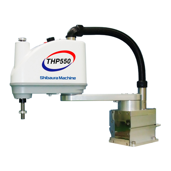
THP550-IP
TH450A-IP
TH550A-IP/TS3000
INDUSTRIAL ROBOT SPECIFICATIONS
1.
Make sure that this instruction manual is delivered to the final
user of Toshiba Machine's industrial robot.
2.
Before operating the industrial robot, read through and
completely understand this manual.
3.
After reading through this manual, keep it nearby for future
reference.
INSTRUCTION MANUAL
DUST- & DRIP-PROOF TYPE
Notice
March, 2010
TOSHIBA MACHINE CO., LTD.
STE80783-0
Advertisement
Table of Contents

Related Manuals for Toshiba THP550-IP


Summary of Contents for Toshiba THP550-IP
- Page 1 INDUSTRIAL ROBOT SPECIFICATIONS Notice Make sure that this instruction manual is delivered to the final user of Toshiba Machine’s industrial robot. Before operating the industrial robot, read through and completely understand this manual. After reading through this manual, keep it nearby for future reference.
- Page 2 DUST- & DRIP-PROOF TYPE SPECIFICATIONS MANUAL Copyright 2010 by Toshiba Machine Co., Ltd. All rights reserved. No part of this document may be reproduced in any form without obtaining prior written permission from Toshiba Machine Co., Ltd. The information contained in this manual is subject to change without prior notice to effect improvements.
- Page 3 DUST- & DRIP-PROOF TYPE SPECIFICATIONS MANUAL Preface This manual describes the specifications of the THP550/TH450A/TH550A dust- and drip-proof type industrial robot. This manual is essential to keep the robot performance for a long time, to prevent failures and to assure safety. Be sure to look through this manual and set up a maintenance program before actually starting the robot.
- Page 4 Disassembly caused. prohibited • Always use the Toshiba Machine's designated spare parts when replacing the parts. • Maintenance and inspection should be performed regularly. Otherwise, the system may malfunction or accidents will be Mandatory caused.
- Page 5 DUST- & DRIP-PROOF TYPE SPECIFICATIONS MANUAL This manual is comprised of the following seven (7) sections: Section 1 Specifications This section describes the basic specifications and names of respective parts for the dust- and drip-proof type industrial robot. Section 2 Transportation This section describes how to remove the dust- and drip-proof type robot from its box and how to transport it to the installation site.
-
Page 6: Table Of Contents
DUST- & DRIP-PROOF TYPE SPECIFICATIONS MANUAL Table of Contents Page Specifications ......................7 Name of Each Part ..................7 Outer Dimensions ....................8 Specifications Table ..................14 Transportation ......................16 Unpacking......................16 Transportation....................16 2.2.1 Mass and Outer Dimensions .............17 2.2.2 Transporting the Robot..............19 Installation ......................21 Installation Environment ................21 Ingress Protection (IP) Class of Dust- and Drip-Proof Specification ....22 Air Purge......................23 Coordinate System ..................24... - Page 7 DUST- & DRIP-PROOF TYPE SPECIFICATIONS MANUAL Mounting and Dismounting Covers..............42 5.5.1 Base Cover ..................42 5.5.2 Arm 1 Covers ..................44 5.5.3 Arm 2 Cover ..................45 Cleaning Robot Body....................47 Replacement Parts for Maintenance...............48 Replacement Parts List for Maintenance ............48 Optional Parts......................49 List of Optional Parts ..................49 STE80783 –...
-
Page 8: Specifications
DUST- & DRIP-PROOF TYPE SPECIFICATIONS MANUAL Specifications Name of Each Part The names of respective parts of the dust- and drip-proof type robot are shown in Fig. 1.1 below. The figure shows the THP550-IP. Axis 2 (rotation) Wiring panel Cover... -
Page 9: Outer Dimensions
Brake OFF switch Mounting hole (4×φ14) Hand air joint: For 4×φ 4 tube Z150: Upper limit Z300: Upper limit Space required for cable connection Z150: Origin Z300: Origin Fig. 1.2 Outer dimensions of the robot (THP550-IP) STE80783 – 8 –... - Page 10 DUST- & DRIP-PROOF TYPE SPECIFICATIONS MANUAL Mounting hole (4×φ14) Hand air joint: For 4×φ 4 tube Hand I/O connector Brake OFF switch Space required for cable connection Fig. 1.3 Operating range of the robot (TH450A-IP) STE80783 – 9 –...
- Page 11 DUST- & DRIP-PROOF TYPE SPECIFICATIONS MANUAL Mounting hole (4×φ14) Hand air joint: For 4×φ 4 tube Hand I/O connector Brake OFF switch Space required for cable connection Fig. 1.4 Operating range of the robot (TH550A-IP) STE80783 – 10 –...
- Page 12 DUST- & DRIP-PROOF TYPE SPECIFICATIONS MANUAL (Axis 1 operating range) (Axis 1 operating range) Fig. 1.5 Operating range of the robot (THP550-IP) STE80783 – 11 –...
- Page 13 DUST- & DRIP-PROOF TYPE SPECIFICATIONS MANUAL (Axis 1 operating range) (Axis 1 operating range) Fig. 1.6 Operating range of the robot (TH450A-IP) STE80783 – 12 –...
- Page 14 DUST- & DRIP-PROOF TYPE SPECIFICATIONS MANUAL (Axis 1 operating range) (Axis 1 operating range) Fig. 1.7 Operating range of the robot (TH550A-IP) STE80783 – 13 –...
-
Page 15: Specifications Table
DUST- & DRIP-PROOF TYPE SPECIFICATIONS MANUAL Specifications Table Item Specifications Structure Horizontal multi-joint type SCARA robot Model THP550-IP Ingress protection (IP) class of dust- and IP65 (*1) drip-proof structure Applicable controller TS3000 (*2) Mass of robot body 27 kg No. of controlled axes... - Page 16 DUST- & DRIP-PROOF TYPE SPECIFICATIONS MANUAL Item Specifications Structure Horizontal multi-joint type SCARA robot Model TH450A-IP TH550A-IP Ingress protection (IP) class of dust- and IP65 (*1) drip-proof structure Applicable controller TS3000 (*2) Mass of robot body 28 kg 29 kg No.
-
Page 17: Transportation
DUST- & DRIP-PROOF TYPE SPECIFICATIONS MANUAL Transportation Unpacking The robot and controller are shipped separately in wooden crates or corrugated cardboards. Open the packages in a location easily accessible, where the equipment is to be installed. Take careful precautions not to damage the robot and controller. After opening the packages, make sure that all the accessories are present and that no part has been damaged during transport. -
Page 18: 2.2.1 Mass And Outer Dimensions
DUST- & DRIP-PROOF TYPE SPECIFICATIONS MANUAL 2.2.1 Mass and Outer Dimensions The mass and outer dimensions of the robot are shown in Fig. 2.1 to Fig. 2.3. Fig. 2.1 Outer dimensions at transport (THP550-IP) Mass of main robot = 27 kg Fixture Fig. - Page 19 DUST- & DRIP-PROOF TYPE SPECIFICATIONS MANUAL Mass of main robot = 28 kg Fixture Fig. 2.2 Outer dimensions at transport (TH450A-IP) Mass of main robot = 29 kg Fixture Fig. 2.3 Outer dimensions at transport (TH550A-IP) STE80783 – 18 –...
-
Page 20: 2.2.2 Transporting The Robot
DUST- & DRIP-PROOF TYPE SPECIFICATIONS MANUAL 2.2.2 Transporting the Robot The dust- and drip-proof type robot equals the standard robot added with a cap and bellows. The precautions to be taken at transport are stated below. The precautions other than the below are the same as in the standard robot. See the TH650A Installation and Transportation Manual provided separately. - Page 21 DUST- & DRIP-PROOF TYPE SPECIFICATIONS MANUAL CAUTION • When lifting up the robot by workers, hold the shaded locations by hands, as shown in Fig. 2.4. If the ball screw spline shaft is held by hands, an unusually large force is exerted, resulting in a malfunction. •...
-
Page 22: Installation
DUST- & DRIP-PROOF TYPE SPECIFICATIONS MANUAL Installation Installation Environment Table 3.1 shows the environmental conditions for the location in which the robot and controller are to be installed. Table 3.1 Environmental conditions for robot and controller Item Specifications Temperature In operation 0 to 40°C In storage –10 to 50°C... -
Page 23: Ingress Protection (Ip) Class Of Dust- And Drip-Proof Specification
DUST- & DRIP-PROOF TYPE SPECIFICATIONS MANUAL Ingress Protection (IP) Class of Dust- and Drip-Proof Specification For the dust- and drip-proof specification of THP550, the ingress protection (IP) class against dust and water is IP65 or equivalent. Be sure to perform air purge. Under some operating environment, water or dust may enter. -
Page 24: Air Purge
DUST- & DRIP-PROOF TYPE SPECIFICATIONS MANUAL Air Purge The dust- and drip-proof type robot is provided with an air supply port for air purge in its base connector unit. See Para. 1.1. (Quick-operated joint with speed controller) By feeding air into the air supply port, entry of dust into the robot can be prevented. The air supply unit (reducer or pressure reducing valve, air filter, etc.) and air tube (8 mm-dia.) should be provided by the customer. -
Page 25: Coordinate System
Axis 2 Axis 1 Origin of base coordinate system When Z-axis stroke is 150 mm Origin of base coordinate system When Z-axis stroke is 300 mm Fig. 3.1 Base coordinate system and joint angle origin (THP550-IP) STE80783 – 24 –... - Page 26 DUST- & DRIP-PROOF TYPE SPECIFICATIONS MANUAL Reference surface Reference surface Axis 2 Axis 1 Origin of base coordinate system When Z-axis stroke is 150 mm Fig. 3.2 Base coordinate system and joint angle origin (TH450A-IP/TH550A-IP) STE80783 – 25 –...
-
Page 27: Installing The Robot
DUST- & DRIP-PROOF TYPE SPECIFICATIONS MANUAL Installing the Robot The robot is secured, using the set holes on the base (four (4) places). Use M12 hexagon socket head cap screws. The robot installation method is shown in Fig. 3.3. The reference surfaces are provided on the base. -
Page 28: Cable Connection
DUST- & DRIP-PROOF TYPE SPECIFICATIONS MANUAL Cable Connection The connector layout and connection method on the controller side are the same as in the standard robot. See the THP550 Installation and Transportation Manual and TH450A/TH550A Installation and Transportation Manual provided separately. For the dust- and drip-proof type robot, the connector on the robot side differs from that of the standard robot. -
Page 29: Connector Terminal Layout
DUST- & DRIP-PROOF TYPE SPECIFICATIONS MANUAL To connect the connector, make sure of the top and bottom sides of the connector, completely insert the cable side connector into the robot side connector, then lock the lever of the robot side connector completely. An incomplete lock can cause a contact failure or other accident. -
Page 30: Tool Interface
DUST- & DRIP-PROOF TYPE SPECIFICATIONS MANUAL Tool Interface Mounting of a tool and tool signals are the same as in the standard robot. For details, see the THP550 Installation and Transportation Manual and TH450A/ TH550A Installation and Transportation Manual provided separately. Tool Wiring Five (5) input signals are provided for sensors, etc. -
Page 31: How To Connect Connectors
DUST- & DRIP-PROOF TYPE SPECIFICATIONS MANUAL Type of connector: JOES SMP–10V–BC (Maker: J.S.T. Mfg.) JOFS SMP–11V–BC (Maker: J.S.T. Mfg.) Type of contact: BHF–001T–0.8SS (Maker: J.S.T. Mfg.) Adaptive cable: Conductive cross section area: 0.2 mm ~ 0.3 mm Opposite connector type Type of connector: JOEP SMR–10V–B (Maker: J.S.T. - Page 32 DUST- & DRIP-PROOF TYPE SPECIFICATIONS MANUAL Cable clamp Rubber bushing Terminal crimping Filler From PLC, etc. Connectors Cover (rubber) Rubber (JOFS, JOES) User cable bushing Fig. 4.2 How to connect connectors Remove the motor cover of the base unit. For the dust- and drip-proof specification, liquid gasket is coated on the motor cover set surface.
- Page 33 DUST- & DRIP-PROOF TYPE SPECIFICATIONS MANUAL Input/output signal connector CN0 Signal Input/output circuit Signal name (Cannon) and example of connections D-IN0 Input signal 0 P24V Customer’s side D-IN1 Input signal 1 D-IN2 Input signal 2 D-IN3 Input signal 3 D-IN4 Input signal 4 D-IN5 Input signal 5...
- Page 34 DUST- & DRIP-PROOF TYPE SPECIFICATIONS MANUAL By using the DC24 V power of the controller, a relay, solenoid valve, etc., can be driven. When the external power is used, GND of the external power should be common to GND (PG) of the robot controller. Output specification: Rated voltage DC24 V (max.
- Page 35 DUST- & DRIP-PROOF TYPE SPECIFICATIONS MANUAL Fig. 4.4 Tool wiring diagram STE80783 – 34 –...
-
Page 36: Tool Air Piping
DUST- & DRIP-PROOF TYPE SPECIFICATIONS MANUAL Tool Air Piping The robot is provided four (4) air lines for the tool. The outer diameter of the air pipelines is 4 mm. Fig. 4.5 shows the tool air piping. The air control unit (oiler, regulator with gage and filter) and solenoid valves should be provided by the user. -
Page 37: Maintenance
DUST- & DRIP-PROOF TYPE SPECIFICATIONS MANUAL Maintenance The basic structure of the dust- and drip proof type robot is the same as that of the standard robot. For the contents of inspection, etc., see the THP550 Maintenance Manual and TH450A/TH550A Maintenance Manual provided separately. This section deals with the layout of the robot mechanical components and the procedures for mounting and dismounting the covers and for replacing the bellows. -
Page 38: Layout Of Robot Components
Axis 2 motor Axis 2 reduction gear Axis 3 timing belt Axis 4 timing belt Axis 1 reduction gear Bellows Ball screw spline shaft Battery box Axis 1 motor Fig. 5.1 Layout of robot mechanical components (THP550-IP) STE80783 – 37 –... -
Page 39: Tools And Supplies For Maintenance
DUST- & DRIP-PROOF TYPE SPECIFICATIONS MANUAL Axis-4 motor Axis-3 motor Bellows Axis 4 reduction gear Axis 2 motor Axis 2 reduction gear Axis 1 reduction gear Axis 3 timing belt Axis 4 timing belt Bellows Ball screw spline shaft Battery box Axis 1 motor Fig. -
Page 40: Replacing Bellows
DUST- & DRIP-PROOF TYPE SPECIFICATIONS MANUAL Replacing Bellows Replacement of the bellows is performed by our after-sale service engineer. If bellows is replaced by the customer, we will not guarantee any consequential troubles or accidents. DANGER • Before replacing the bellows with a new one, be sure to turn off the controller power and remove the power plug. -
Page 41: Replacing Upper Bellows
DUST- & DRIP-PROOF TYPE SPECIFICATIONS MANUAL To mount the bellows, observe the above steps in the reversed order. Be sure to attach the gasket, and apply the Loctite adhesives to all set bolts. CAUTION • When dismantling the bellows, DO NOT pull it out by force. Otherwise, the bellows may rupture. - Page 42 DUST- & DRIP-PROOF TYPE SPECIFICATIONS MANUAL Shaft for bellows Bellows Setscrew Gasket Attached to the Lower keep plate keep plate Upper keep plate Gasket Attached to the Setscrew bearing case Wiring guide Bearing case Bellows mounting ring Bellows mounting ring No need to be removed No need to be removed Arm-2 cover...
-
Page 43: Mounting And Dismounting Covers
DUST- & DRIP-PROOF TYPE SPECIFICATIONS MANUAL Mounting and Dismounting Covers A gasket (i.e., rubber packing) is attached to each cover set surface of the dust- and drip-proof type robot. Also, as the liquid gasket is coated to some areas, the mounting and dismounting procedures of each cover differ from those of the standard robot. - Page 44 DUST- & DRIP-PROOF TYPE SPECIFICATIONS MANUAL Also, apply the Loctite adhesives to all set bolts. CAUTION • Do not forget to install the gasket. Also, be sure to coat the Loctite adhesives to all set bolts. Otherwise, the dust- and drip-proof performance is damaged to cause entry of water or dust.
-
Page 45: Arm 1 Covers
1 with eight (8) cross-recessed truss head screws (M4 × 6) by inserting the gasket. Arm cover Gasket Fig. 5.7 Arm 1 covers (THP550-IP) Apply the Loctite adhesives to all set bolts. Arm cover Gasket Fig. 5.7 Arm 1 covers (TH450A-IP/TH550A-IP) STE80783 –... -
Page 46: Arm 2 Cover
DUST- & DRIP-PROOF TYPE SPECIFICATIONS MANUAL CAUTION • Do not forget to install the gasket. Also, be sure to coat the Loctite adhesives to all set bolts. Otherwise, the dust- and drip-proof performance is damaged to cause entry of water or dust. - Page 47 DUST- & DRIP-PROOF TYPE SPECIFICATIONS MANUAL When mounting the cover, apply the liquid gasket to the area shown in Fig. 5.8 above. Also, apply the Loctite adhesives to all set bolts. CAUTION • When using the cutter, take careful precautions not to cut the gasket body. •...
-
Page 48: Cleaning Robot Body
DUST- & DRIP-PROOF TYPE SPECIFICATIONS MANUAL Cleaning Robot Body To clean and wash the robot body, be sure to use a neutral detergent. Use a soft sponge and waste cloth, and take careful precautions not to cut or scratch the robot body. -
Page 49: Replacement Parts For Maintenance
Our dwg. Type Unit code Maker Q’ty Remarks name Bellows S849728 Y610A3F90 Toshiba When Z-axis stroke is Machine 150 mm THP550-IP Bellows S854887 Y610A3FT0 Toshiba When Z-axis stroke is Machine 300 mm THP550-IP Bellows Toshiba When Z-axis stroke is S854575 Y610A3GH0... -
Page 50: Optional Parts
Optional Parts List of Optional Parts Part name Type Our dwg. No. Unit code Maker Q’ty Remarks S854768 Y610A3F40 Toshiba Set of assembly Machine connectors and clamps • Contact us for the purchase of optional parts. STE80783 – 49 –... - Page 51 DUST- & DRIP-PROOF TYPE SPECIFICATIONS MANUAL APPROVED BY: CHECKED BY: PREPARED BY: STE80783 – 50. –...
Need help?
Do you have a question about the THP550-IP and is the answer not in the manual?
Questions and answers