Cabletron Systems SmartSwitch 6500 User Manual
Cabletron systems user guide smartswitch 6500
Hide thumbs
Also See for SmartSwitch 6500:
- Reference manual (358 pages) ,
- Installation and setup manual (62 pages) ,
- Overview and setup manual (50 pages)
Table of Contents
Advertisement
Quick Links
Download this manual
See also:
Reference Manual
Advertisement
Table of Contents
Troubleshooting

Related Manuals for Cabletron Systems SmartSwitch 6500


Summary of Contents for Cabletron Systems SmartSwitch 6500
- Page 1 SmartSwitch 6500 User Guide 35 Industrial Way Rochester, NH 03866 (603) 332-9400 Part Number 04-0050-01 Rev. A Order Number 9032706...
- Page 2 Cabletron Systems reserves the right to make changes in specifications and other information contained in this document without prior notice. The reader should in all cases consult Cabletron Systems to determine whether any such changes have been made. The hardware, firmware, and software described in this manual are subject to change without notice.
-
Page 3: Fcc Class A Notice
This equipment uses, generates, and can radiate radio frequency energy and if not installed in accordance with the SmartSwitch 6500 User Guide, may cause harmful interference to radio communications. Operation of this equipment in a residential area is likely to cause interference in which case the user will be required to correct the interference at his own expense. -
Page 4: Declaration Of Conformity Addendum
Equipment Type/Environment: We the undersigned, hereby declare, under our sole responsibility, that the equipment packaged with this notice conforms to the above directives. Manufacturer: Legal Repersentative in Europe: iv SmartSwitch 6500 User Guide 89/336/EEC 73/23/EEC Cabletron Systems, Inc. 35 Industrial Way P. - Page 5 Do not use optical instruments to view the laser output. The use of optical instruments to view laser output increases eye hazard. When viewing the output optical port, you must remove power from the network adapter. watts. or 8x10 SmartSwitch 6500 User Guide v sr-1.
- Page 6 Reconnect cable and check for proper mating. If problems remain, gently wipe out optical port with a DRY fiber port cleaning swab and repeat step 1. To avoid contamination, replace port caps on all fiber optic devices when not Warning in use. vi SmartSwitch 6500 User Guide...
- Page 7 REGULATORY COMPLIANCE SUMMARY SAFETY The SmartSwitch 6500 meets the safety requirements of UL 1950, CSA C22.2 No. 950, EN 60950, IEC 950, and 73/23/EEC. The SmartSwitch 6500 meets the EMC requirements of FCC Part 15, EN 55022, CSA C108.8, VCCI V-3/93.01, EN 50082-1, and 89/336/EEC.
-
Page 8: Revision History
REVISION HISTORY Document Name: SmartSwitch 6500 User Guide Document Part Number: 04-0050-01 Rev. A Document Order Number: 9032706 Author: Bruce Jordan Editor: Carre Gibson Illustrator: Mike Fornalski Date Revision #VÍœLiÀÊ£™™n " viii SmartSwitch 6500 User Guide Description Initial release... -
Page 9: Table Of Contents
TABLE OF CONTENTS Introducing the SmartSwitch 6500 ....... . 1-1 SmartSwitch 6500 Modules . - Page 10 Connecting to Local Switch Client Through a PVC ....... . .
- Page 11 SmartSwitch 6500 MIB Support ........
- Page 12 Index ............I-1 SmartSwitch 6500 User Guide...
-
Page 13: List Of Figures
Cabletron SmartSwitch 6500 object identifier example ........ - Page 14 List of Figures xiv SmartSwitch 6500 User Guide...
-
Page 15: List Of Tables
Module combinations in 6500 chassis ........ - Page 16 List of Tables SmartSwitch 6500 User Guide...
-
Page 17: Introducing The Smartswitch 6500
SmartSwitch 6C110 chassis with other Cabletron networking devices. For example, the slots of the 6C110 chassis can be populated by a mix of SmartSwitch 6500 modules and SmartSwitch 6000 Ethernet switches. Both the CSM and TSM are hot swappable. This means that you can install and remove TSMs and CSMs from the 6C110 chassis without turning of chassis power. -
Page 18: Smartswitch 6500 Modules
For redundancy, the SmartSwitch 6500 supports up to two CSMs in a single 6C110 chassis. When one CSM is active, the other CSM is in standby mode. If the active CSM fails, the standby CSM can be made to assumes the active role. -
Page 19: Input/Output Modules (Ioms)
Input/Output Modules (IOMs) IOMs provide the physical ATM ports for the SmartSwitch 6500 and are mounted as daughter cards on the TSMs. The TSMs of the SmartSwitch 6500 support a number of different I/O modules with a variety of interfaces and media types;... - Page 20 SmartSwitch 6500 Modules Introducing the SmartSwitch 6500 1-4 SmartSwitch 6500 User Guide...
-
Page 21: Switch Installation And Setup
For detailed information about setting up the SmartSwitch Chassis (6C110), see the 6C110 SmartSwitch 6500 Overview and Setup Guide. RECEIVING THE SMARTSWITCH 6500 Your SmartSwitch 6500 is shipped to you in several cartons. The number of cartons and their contents depends on which components you order. 2.1.1 Inspecting the Order The following is a general list of cartons and their contents that comprise a SmartSwitch 6500. -
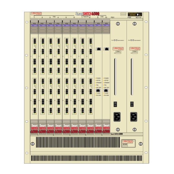
Page 22: Figure 2-1 Smartswitch 6500 Chassis
Receiving the SmartSwitch 6500 Switch Installation and Setup Figure 2-1 SmartSwitch 6500 chassis 2-2 SmartSwitch 6500 User Guide... -
Page 23: Unpacking
2.1.2 Unpacking Carefully unpack each component of the SmartSwitch 6500 (chassis, TSMs, CSM, and so on). Inspect each component for damage. Do not attempt to install damaged components. Contact the Cabletron Systems Global Contact Center immediately (see Appendix C, "Technical Support") Inspect the TSMs. -
Page 24: Check Accessory Carton Contents
— CD-ROM containing SmartSwitch ATM Administrator software for Windows 95/98, Windows NT, and Solaris 2.4/2.5 — CD-ROM containing the SmartSwitch 6500 User Guide, Reference Manual, related manuals, and Acrobat Reader If any of these items is missing, contact the Cabletron Systems Global Contact Center immediately. -
Page 25: Switch Installation And Assembly
Switch Installation and Setup SWITCH INSTALLATION AND ASSEMBLY The following is a list of steps for assembling your SmartSwitch 6500. Refer to Figure 2-4 for proper module placement. 2.2.1 Mounting the Chassis Find someone to assist you. The SmartSwitch 6500 chassis is heavy enough to make this a two-person task. - Page 26 Insert the power cord into its receptacle on the front of the power supply. Plug the other end of the power cord into an appropriate power outlet. If your SmartSwitch 6500 has a second power supply, repeat steps 1 through 5. 2-6 SmartSwitch 6500 User Guide...
-
Page 27: Installing The Csm
Remove the metal blank that covers either slot 9 or slot 10 of the chassis (CSMs can reside only in slots 9 and 10). See the legend on the top edge of the SmartSwitch 6500 chassis. Open the ejectors at the top and bottom of the CSM module. - Page 28 T X D A T A R X D A T A Circuit Card Metal Backpanel Card Guides Figure 2-5 Installing CSM in slot 9 2-8 SmartSwitch 6500 User Guide Rotate ejector to lock in place Switch Installation and Setup...
-
Page 29: Installing The Tsm With Cpu Daughter Board
Remove the metal blank that covers either slot 7 or slot 8 of the chassis (TSMs with CPU daughter cards can reside only in slots 7 and 8). See the legend on the top edge of the SmartSwitch 6500 chassis. - Page 30 Switch Installation and Assembly Circuit Card Metal Backpanel Card Guides Figure 2-7 Installing a TSM/CPU module in slot 8 2-10 SmartSwitch 6500 User Guide Rotate ejector to lock in place Switch Installation and Setup...
-
Page 31: Installing Additional Tsm Modules
Installing Other Modules in the SmartSwitch 6500 Chassis If all SmartSwitch 6500 chassis slots are not occupied by TSMs, other Cabletron SmartSwitch double-wide devices can reside within the chassis. For example, if slots are available, the chassis can also contain Ethernet switches, other ATM switches, and so on (see Figure 2-8 for an example). -
Page 32: Figure 2-8 Smartswitch 6500 Chassis With Ethernet Switch, Tsms, And Csms
17 18 19 20 21 22 23 24 Figure 2-8 SmartSwitch 6500 chassis with Ethernet switch, TSMs, and CSMs Table 2-2 Module combinations in 6500 chassis Number of double-wide 6000 modules Installed Number of TSM modules that can be installed... -
Page 33: Configuring The Switch
RJ-45 jack labeled ENET (see Figure 2-9). Start the dumb terminal or workstation terminal emulation software. As soon as power is applied to the SmartSwitch 6500, the module emits a series of diagnostic messages. After the diagnostics are finished, the switch prompts for a password. Enter the default password, “admin.”... - Page 34 Configuring the Switch Switch Installation and Setup • Default router — IP address of router (if any) that exists between the switch and its TFTP server. 2-14 SmartSwitch 6500 User Guide...
- Page 35 Only one console connection is allowed at any time. To reach the SmartSwitch Note 6500 through telnet, you must exit the local terminal connection by entering the command. exit < “admin” is the default password...
-
Page 36: Backup/Redundancy Configuration
2.3.2 Backup/Redundancy Configuration Backup/redundancy configuration consists of setting up the SmartSwitch 6500 to save configuration backup files used by the master TSM/CPU and slave TSM/CPU (if any). The backup configuration file contains all configuration changes made to the master TSM/CPU. For example, the backup file contains ELAN information, port configuration changes, PVCs, and so on. - Page 37 Perform the following steps to configure backup capabilities. On a workstation that can be reached by your SmartSwitch 6500 and is running TFTP server software, create a file under the /tftpboot directory. This file is used as the backup file by the master TSM/CPU and can initially be blank.
- Page 38 Redundancy Configuration for CSMs The SmartSwitch 6500 can use two CSM modules: one active (master), the other in standby (slave). By default, the CSM in slot 9 is recognized as the active (master) CSM by the active TSM/CPU module. To set the slave CSM as the...
-
Page 39: Led Descriptions
CSM not active CSM is not in standby mode Normally off Ethernet interface not active Unlit TSM not initialized No CPU on TSM No data is passing through port. Normally off when connected, Framer is receiving sync SmartSwitch 6500 User Guide 2-19... -
Page 40: Using The Console
RX DATA Ejector Figure 2-10 CSM and TSM LEDs USING THE CONSOLE Use the SmartSwitch 6500 console interface to configure and manage your switch. The following is a description of the console interface and its operation. 2.5.1 Port Numbering The following convention is used for numbering physical ports on the SmartSwitch 6500:... -
Page 41: Console Commands
Switch Installation and Setup 2.5.2 Console Commands For detailed descriptions of all console commands, see the SmartSwitch 6500 Note Reference Manual. All console commands use the syntax: operator switch-attribute [<parameter 1> <parameter 2>... <parameter n>] Where the is one of the following: operator : Make a connection active. - Page 42 In the example above, the default of “ you can enter a specific port number. Note When you accept the ( abridged. 2-22 SmartSwitch 6500 User Guide is the parameter indicating that you want to show configuration Current pnni10 symmetric...
-
Page 43: Console Time-Out
The console can be configured to exit if it does not sense a key stroke within a defined length of time. By default, the SmartSwitch 6500 is set to never time out (value = 0). To activate the time-out feature, use the... -
Page 44: Console Help
Ptse Smart6500 # 2.5.6 Console Help The console provides several levels of help for console commands. For example, to list the switch attributes that can be used with a particular operator, enter the word Smart6500 # help add HELP ----... -
Page 45: Smartswitch Atm Administrator
Use a graphical user interface • Perform drag and drop operations • Manage all switches from one console • Perform transactions across multiple switches (for example, create an ELAN when the servers are not co-located) SmartSwitch ATM Administrator SmartSwitch 6500 User Guide 2-25... -
Page 46: Figure 2-11 Smartswitch Atm Administrator
For Solaris 2.4/2.5, the following hardware configuration is required: • Ultra-1 Sparc workstation or equivalent • CD-ROM drive • 100 MB free disk space • 64 MB RAM • 200 MB virtual memory (swap space) 2-26 SmartSwitch 6500 User Guide Switch Installation and Setup... -
Page 47: Pc Installation
Table 2-5 Default accounts and passwords User Name Access Level admin read/write guest read only setup.exe pkgadd -d /cdrom/<cd drive> . The SmartSwitch ATM Administrator Login dialog box ssadmin Default Password admin guest SmartSwitch ATM Administrator SmartSwitch 6500 User Guide 2-27... -
Page 48: Default Community Strings
The SmartSwitch ATM Administrator window appears. On the Applications menu, select User Management. 2.6.5 Default Community Strings The following is a list of the default community strings used by the SmartSwitch 6500: • public — Used for all standard SNMP communication •... -
Page 49: Ip Over Atm And Lane
3 IP OVER ATM AND LANE This chapter describes working with the SmartSwitch 6500 IP over ATM VLAN and emulated LAN capabilities. At the end of this chapter you will be able to use your SmartSwitch 6500 switch to •... - Page 50 IP over ATM VLAN is functional by pinging from one end device to another. To make certain that all end devices are registered with the ARP server, you can inspect the switch’s ARP table using command. For example, if three end devices with IP addresses 90.1.1.2, 90.1.1.3, and 90.1.1.4 are...
-
Page 51: Default Atm Addressing For Ip Over Atm
IP over ATM client address = 39:00:00:00:00:00:00:00:00:00:A3:87:0B:00:00:5A:01:01:01:00 CREATING AN EMULATED LAN This section describes the steps for implementing an Ethernet Emulated LAN (ELAN) on your SmartSwitch 6500. The following assumptions are made: • The SmartSwitch 6500 switch will contain a client on the ELAN •... - Page 52 SmartCell ZX # start lecs NOTICE - 'LECS' ***** LECS started ***** SmartCell ZX # Create an ELAN on your SmartSwitch 6500 switch by executing the following is an example. SmartCell ZX # add elan ELANNumber(0) : 1...
- Page 53 Your ELAN is now operational. Additional ELANs can be created in the same way. Note While it is possible for a single ELAN on the SmartSwitch 6500 switch to support multiple subnets, in general, switch performance is best (and management easiest) when the “One-subnet-per-ELAN”...
-
Page 54: Atm Addressing For Lan Emulation
Creating an Emulated LAN 3.2.1 ATM Addressing for LAN Emulation The SmartSwitch 6500 provides default formats for ATM addresses used by LAN emulation entities (local client, LECS, LES, and BUS). The default formats are constructed as follows. Default Netprefix The default netprefix is constructed from... -
Page 55: Elans Across Multiple Switches
VLAN and the SmartSwitch 6500 CPU; this CPU connection appears as if the switch is an end station on the VLAN. The SmartSwitch 6500 uses local clients to connect itself to the VLANs that it supports. This is analogous to a phone company that supports a communication system. Even though the phone company maintains the circuits, a call to the phone company itself cannot be made unless the phone company has its own number and connection on its own phone system. -
Page 56: Distributed Lane Services
Distributed LANE Services LANE services (LECS, LES, and BUS) can reside on different SmartSwitch 6500s. For example, the LECS can reside on one SmartSwitch 6500, while the LES and BUS reside on another. Use the to distribute LANE services among SmartSwitch 6500s. -
Page 57: Elan Join Policies
3.2.5 ELAN Join Policies The SmartSwitch 6500 provides control over the assigning of clients to ELANs. Control is accomplished by ELAN join policies. By default, the SmartSwitch 6500 has a single ELAN join policy defined — attempts to join LANE services, the SmartSwitch 6500 uses information provided by the client to performs the Effort ELAN join test. - Page 58 If the default ELAN (ELAN 0) has been deleted, the client is dropped. Note By using ELAN join policies, clients attempting to join LANE services can be assigned to specific ELANs. Table 3-1 lists the ELAN join policies that can be configured on the SmartSwitch 6500. Table 3-1 ELAN Join Policies Policy No.
- Page 59 Priority Value 65001 < The created policy, its index number, and its priority 1000 add lecselanlec list by one (or a combination of) the following attributes: Creating an Emulated LAN Best Effort command. Use the SmartSwitch 6500 User Guide 3-11...
- Page 60 To specify a TLV set with the Note currently exist. Use the detailed information on the Reference Manual. 3-12 SmartSwitch 6500 User Guide : 39:00:00:00:00:00:00:00:00:00:44:55:66:11:22:33:44:55:66:00 < No MAC address is specified : 204.123.91.7 < ELAN is specified by ELAN number <...
-
Page 61: Pnni Routing
The SmartSwitch 6500 assigns default Node ATM Addresses based on the following format: Default Node ATM Address = 39 + nine zero (00) bytes + last three bytes of chassis MAC address + switch MAC address with 127 summed with the last byte + byte containing node index starting at... -
Page 62: Multi-Level Pnni Topology
Set the peer group IDs of SmartSwitch 6500s to differentiate their peer group membership. • Select one (or more) SmartSwitch 6500 within each peer group as the Peer Group Leader (PGL). • Add a higher-level PNNI node to each PGL switch. This higher-level node represents its peer group as a Logical Group Node (LGN) within the next highest (parent) peer group. -
Page 63: Figure 4-1 Physical Connectivity For Multi-Peer Group Example
Console: You will have to reboot for the new node configuration to take effect. A1 # Reboot the switch, and repeat the process for switches SWA2 and SWA3. SWA3 SWB3... - Page 64 =========================================================================== 206.61.237.20 206.61.237.19 A3 # Select switch SWA3 to be the PGL of group A and switch SWB3 to be the PGL of group B. Use the command to add a second, higher-level, node to switch SWA3: add pnninode A3 # add pnninode...
- Page 65 ParentNodeIndex(0) InitTime(15) OverrideDelay(30) ReElectTime(15) B3 # Use the show pnnipglelection the PGLs of their respective peer groups. For example, on switch SWA3, enter the following: A3 # show pnnipglelection NodeIndex(1) PGL Election Information ================================================================================ Node Index Leadership Priority : 100...
-
Page 66: Physical Connections Between Peer Groups
Multi-level PNNI Topology Connectivity is now established between the two peer groups. For example, if LANE services are running on a switch within peer group A, LANE clients can exist in group B. The clients in group B will traverse the link between the two groups, find the LANE server in group A, and join the ELAN. -
Page 67: Figure 4-3 Adding A Third Pnni Node For Next Level Connectivity
PNNI Routing Add a third node (at level 64) to either switch SWA3 or SWB3. Use the command to designate the switch’s second node (not third) as the set pnnipglelection PGL for the parent peer group, and specify the third node as the parent node of the second. -
Page 68: Managing Parallel Pnni Links
By default, parallel links are considered to have equal capabilities with regard to call set ups. For example, if a second link is added between switch A3 and switch B3 (from the example above), this parallel link can be seen using the... -
Page 69: Aggregation Tokens
Continuing with the earlier example of multi-level topologies, add a second physical PNNI link between peer groups A and B by physically connecting switch SWA2 to switch SWB2. By setting the aggregation token of this physical link to a value different from the physical link connecting switches SWA3 and SWB3, a second logical link appears within the parent group. -
Page 70: Figure 4-4 Aggregation Token Values And Parallel Links
Managing Parallel PNNI Links PNNI Routing The physical connection from switch SWA2 to switch SWB2 is now advertised as a second logical link within the parent peer group (see Figure 4-4). Second Logical Link First Logical link Level 72 First Physical... -
Page 71: Routing
The proper route type is determined by the SmartSwitch 6500 through interface signaling information. IISP ROUTES Use the command to create an IISP route that links the SmartSwitch 6500 to a device that supports only add atmroute IISP routing. For example, Physically connect port of the SmartSwitch 6500 to the IISP device. -
Page 72: Iisp Routing Considerations
SmartSwitch 6500. Conversely, there must be a SmartSwitch 6500 that has a direct physical link (and a route over that link) to the IISP device. The following two examples illustrate this point. -
Page 73: Figure 5-1 Iisp Route Across Pnni Domain
IISP Routing Example Two A second IISP device (Switch D) is added behind Switch A. If Switch D also needs to reach Switch C for LANE support, additional IISP routes must be defined between Switches D and C, B and D, and A and D. Figure 5-2 shows the typical “route to every point reached”... -
Page 74: Uni Routes
00:11:22:33:44:55) to port 7A2 of the SmartSwitch 6500. If the adapter does not support ILMI or its ILMI is incompatible with the SmartSwitch 6500, you must create a static UNI route between the adapter and port 7A2 of the SmartSwitch 6500. The following is an example:... -
Page 75: Route Metrics
< 1st pair member, we accept the default (Outgoing) : cbr : 200 : 1000 : 750 < 2nd pair member, we set as incoming : incoming : cbr : 200 : 1000 : 750 SmartSwitch 6500 User Guide 5-5 Route Metrics ). The metric tag... -
Page 76: Ip Routing
Smart6500 # IP ROUTING The SmartSwitch 6500 switch provides limited IP routing. IP routing allows switches that are not connected directly to Ethernet to communicate with an Ethernet-based network management system (NMS). The connection is made by adding IP routes on the non-connected switches that specify a client on a connected switch as their gateway to the Ethernet. -
Page 77: Figure 5-3 Ip Routing Through Sw1 For Connectivity To The Ethernet Network
SW2 is connected to SW1 through PNNI, and both switches are part of the same emulated LAN. To reach SW2 with the Ethernet-based NMS, create an IP route that assigns SW1's switch client as SW2's default gateway to the network 128.205.99.0. Enter the following on SW2 (see Figure 5-3): Smart6500 # add route <... - Page 78 IP Routing The NMS must also contain a route that specifies the Ethernet interface of the Note Ethernet connected switch as the gateway to the ELAN subnet. 5-8 SmartSwitch 6500 User Guide Routing...
-
Page 79: Virtual Ports And Static Connections
6.1.1 Point-to-Point PVCs The procedure for setting up a PVC connection between two end nodes through the SmartSwitch 6500 consists of specifying the ports and the Virtual Path Connection Identifier and Virtual Channel Identifiers (VPCI and VCI). add trafficdescriptor... -
Page 80: Point-To-Multipoint Pvcs
6.1.2 Point-to-Multipoint PVCs Instructions in this section describe how to set up a point-to-multipoint connection through your SmartSwitch 6500. Example: Create a point-to-multipoint connection between a broadcasting workstation on port 7a1 and three other workstations connected to ports 7a2, 7a3, and 7a4. - Page 81 Sust Cell Rate Max Burst Size (Kb/s) (Kb/s) CLP_0+1 CLP_0 CLP_0+1 CLP_0 10872 5436 2052 1585 : pmp : 7a1 : 101 : 7a2 : 101 PVC Connections Min Cell Aal Type Rate CLP_0+1 (Kb/s) SmartSwitch 6500 User Guide 6-3...
-
Page 82: Connecting To Local Switch Client Through A Pvc
6.1.3 Connecting to Local Switch Client Through a PVC All PVC connections to the SmartSwitch 6500 local clients use the CPU port. This port is either 7b4 or 8b4 depending on the slot in which the master TSM/CPU module resides. - Page 83 < 1 bit for VPIs: 2 < Specify the second port : 7b1 : down : nnipvc < 1 bit for VPIs: 2 -1 = 1 VPI PVP Connections MaxVpiBits MaxVpiBits -1 = 1 VPI SmartSwitch 6500 User Guide 6-5...
-
Page 84: Connecting Pvps
When connecting to another PVP switch, the VPI numbers assigned to the ports carrying the PVP on each switch must match. For example if a PVP exits switch 1 on port 7a1 and enters switch 2 on port 3b4, the VPI number assigned to port 7a1 on switch 1 and port 3b4 on switch 2 must be the same (see Figure 6-1). -
Page 85: Virtual Ports
Figure 6-1 Terminating PVPs VIRTUAL PORTS The SmartSwitch 6500 supports the ability to create virtual ports. Typically, virtual ports are used for terminating Permanent Virtual Path (PVP) connections. Virtual ports are designated by the following convention: number of the physical port + a period + virtual port number For example, , and so on. - Page 86 UNI, refer to the ATM Forum specification for ILMI 4.0.). The following is a practical, step-by-step example of creating a virtual port on physical port 7a1 that controls a single VPI. 6-8 SmartSwitch 6500 User Guide command to set the number of bits to use set portconfig...
- Page 87 < Set to 1 — this translates to VPIs = 2 < Notice that MaxVciBits has reduced itself by 1 bit is used here twice for the purposes of clarity only. set portconfig Virtual Ports -1 = 1 within the same MaxVpiBits SmartSwitch 6500 User Guide 6-9...
- Page 88 VPI specified by the set portconfig because the Base VPI is beyond the eight VPIs used by 7b2.12 6-10 SmartSwitch 6500 User Guide parameters of the command to create the virtual add port < The .1 means our Base VPI is one (1) : 7a1.1...
- Page 89 Make certain that the traffic descriptors used by the virtual ports were created with the appropriate bandwidth and category of service. in the MaxVpiBits set portconfig in the MaxVpiBits set portconfig Virtual Ports does MaxVpiBits command. command. SmartSwitch 6500 User Guide 6-11...
- Page 90 Virtual Ports Virtual Ports and Static Connections 6-12 SmartSwitch 6500 User Guide...
-
Page 91: Traffic Management
For example, it might be necessary to adjust parameters for a port that carries a large amount of CBR traffic or a very large number of simultaneous connections. The SmartSwitch 6500 provides console commands that affect traffic flow on a global, port, or category of service level. These console commands affect switch traffic flow by controlling •... - Page 92 Traffic Management Capabilities SmartSwitch 6500 user data cells are classified according to the state of a cell loss priority (CLP) bit in the header of each cell. A CLP 1 cell has a lower priority than a CLP 0 cell and is discarded first. Source traffic descriptors can specify CLP 0 cell traffic, CLP 1 cell traffic, or the aggregate CLP 0+1 traffic.
-
Page 93: Call Admission Control Policy
Call Admission Control Policy Call Admission Control (CAC) policy defines the bandwidth allocation scheme used by the CAC when setting up connections. The SmartSwitch 6500 offers three schemes that can be set on a per-port, per-service class basis, • Conservative •... - Page 94 Notice in the example above that the total percentage for all service classes on the port must not exceed 100 percent. Furthermore, if the set cacserviceclassbw virtual ports on that physical port. 7-4 SmartSwitch 6500 User Guide to view the current CAC policies used by each port for each class of set caceqbwallocscheme : 7a1...
-
Page 95: Queue Buffers
7.1.3 Queue Buffers The SmartSwitch 6500 performs buffering using a shared-memory architecture. Buffer space is divided into queues for each class of service. In turn, ports are allocated some portion of each of the service class queues. This allocation is controlled on a per-port basis by the Qos is defined on an end-to-end basis in terms of cell loss ratio, cell transfer delay, and cell delay variation. - Page 96 From the table, we’ll select 128 ( MinIndex 9 for port Smart6500 # set porttrafficcongestion Port(ALL) QueueNumber() MinIndexNumber() MaxIndexNumber() 7-6 SmartSwitch 6500 User Guide : 7a3 1024 4096 4096 8192 8192 ) as its minimum threshold. Use the MinIndex 10 ).
-
Page 97: Efci, Epd, And Rm Cell Marking
7.1.4 EFCI, EPD, and RM Cell Marking To control switch congestion, the SmartSwitch 6500 implements standard resource management cell (RM-cell) marking, explicit forward congestion indicator cell marking (with backward RM cell marking), and early packet discard (EPD). These congestion control schemes are triggered when the number of cells within shared memory reaches user-definable thresholds. - Page 98 Traffic Management Capabilities Traffic Management 7-8 SmartSwitch 6500 User Guide...
-
Page 99: Upgrades And Firmware
Accessing the Boot Load Prompt Boot load commands are executed from the boot load prompt. The boot load prompt is not part of the switch console, and is accessible only after a reboot and before the switch firmware is loaded. Consequently, the boot load commands can be used only through a terminal connection. -
Page 100: Boot Load Commands
POST on or off: ponf Changes start-up action: either run POST before running switch firmware or skip POST and go directly to switch firmware. 8-2 SmartSwitch 6500 User Guide Upgrades and Firmware Parameters = set boot load image 0 as default chpi 0... -
Page 101: Figure 8-1 Memory Locations Affected By The Boot Load Commands
Table 8-1 Boot load commands (Continued) Command Action Switch to the redundant CSM: scsm Tells the SmartSwitch 6500 to transfer CSM mastership to the slave CSM. Switches CPU mastership to other swms TSM/CPU: Changes the slave TSM/CPU to the master. -
Page 102: Upgrading Boot Load Firmware
1 becomes the new default image. Reboot the SmartSwitch 6500 to run the new boot load firmware. Notice that the boot load message at start-up indicates that the SmartSwitch 6500 is now loading and running boot load image 1. -
Page 103: Upgrading Post Diagnostic Firmware
New Default Primary Image Number: 0 => Reboot the SmartSwitch 6500. Boot load image 0 is now used as the default image. Preparing to run Default Primary Image: 0 Enter 0 or 1 to override and force one of these primary image sectors to run: 8.1.4... -
Page 104: Upgrading Switch Operating Firmware
Set up the TFTP/Bootp server software on a workstation. Connect both the TFTP/Bootp server and the SmartSwitch 6500 to your Ethernet network. Make sure that the TFTP/Bootp server can be reached by the SmartSwitch 6500 Ethernet interface. Connect a dumb terminal (or workstation running terminal emulation software) to the SmartSwitch 6500 Terminal port. -
Page 105: Using The Update Firmware Command
RAM is copied into system memory and then run. To use the hot upgrade feature, the SmartSwitch 6500 must have network access to an end station running TFTP server software. The SmartSwitch 6500 operating firmware file must reside within the directory specified by the TFTP server software. - Page 106 Copy the SmartSwitch 6500 operating firmware image into the appropriate location on the TFTP/Bootp server. Set up the TFTP/Bootp server tables (or equivalent file) with the SmartSwitch 6500 MAC address and IP address. You may also need to specify the path to the image file to be downloaded.
-
Page 107: Troubleshooting
You have configured an IP over ATM VLAN, but your network applications are not working. Use these questions and tests to help determine the cause of the problem. Check for connectivity: Try pinging between end nodes and from the SmartSwitch 6500 (using ) to its end nodes. If you cannot ping, check physical connectivity (disconnected cable and so ping on). -
Page 108: Troubleshooting Lan Emulation
You have configured an Emulated LAN and your network applications are not working. Use these questions and tests to help determine the cause of the problem. Check for connectivity. Try pinging between end nodes. Ping from the SmartSwitch 6500 (using ) to its end nodes. If you cannot ping, check physical connectivity (disconnected cable and so ping on). -
Page 109: Troubleshooting Pnni Links
ID. If not the same peer group, perform the following: pnninode Set the peer group ID on either switch to match the other. On the SmartSwitch 6500, use the command to change the peer group ID. -
Page 110: Troubleshooting Congestion
Troubleshooting Congestion Make certain that the switches in the other peer group support multi-level PGLs and border nodes. If not, the other switches must be placed in the same peer group as the SmartSwitch 6500 if you want them to connect. -
Page 111: Port Congestion
Is the UBR queue by a small amount, then wait a few minutes. . Is the number of cells dropped command and set call admission control for this port to a more conservative Troubleshooting Congestion command)? large? MaxValue SmartSwitch 6500 User Guide 9-5... -
Page 112: Events And Alarms
EVENTS AND ALARMS The SmartSwitch 6500 switch records and reports its operation in real-time through the use of events and alarms. An event is an occurrence of a significant activity. For instance, a port going down or a client joining an ELAN are examples of events. -
Page 113: Viewing Events And Alarms
Both events and alarms are stored in shared RAM. However, the 40 most recent alarms are also stored in flash RAM. Storing these 40 alarms in flash RAM makes them persistent between reboots of the SmartSwitch 6500, and provides information about the state of the switch prior to reboot. Note Alarms are collected and stored in flash RAM in groups of four. -
Page 114: Deleting Events And Alarms
Events and Alarms Depending on the activity of your SmartSwitch 6500, the appearance of events on Note the SmartSwitch 6500 may be too frequent to use the SmartSwitch 6500 console comfortably. It is recommended that you turn on the automatic display of events only when troubleshooting. -
Page 115: Saving Core Dumps
SAVING CORE DUMPS The SmartSwitch 6500 core dump feature allows you to specify a local Ethernet host where, in the event of a system failure, the SmartSwitch 6500 sends a copy of its memory. SmartSwitch 6500 system memory is saved to two files, one containing CPU memory (core_cpu), the other common memory (core_cmn). - Page 116 Saving Core Dumps If a system failure occurs while the core dump feature is enabled, the SmartSwitch 6500 console appears similar to the example below. The SmartSwitch 6500 then begins sending images of its memory to the core dump files on the TFTP server.
-
Page 117: Appendix A Specifications
APPENDIX A SPECIFICATIONS This appendix lists the technical specifications for the SmartSwitch 6500 switch. Table A-1 Hardware Specifications Specification Processor Switching engine Max I/O ports* Port-to-port latency CPU DRAM memory Buffer memory (cells) Flash memory Serial port Ethernet port *On TSM/CPU modules, ports 7b4... -
Page 118: Table A-2 Physical Specifications
75 ohm 34.3 Mbps E-3 nonchannelized BNC, coax Table A-4 Protocols Standards and Specifications Protocol Signaling A-2 SmartSwitch 6500 User Guide Value 5 to +40 C (41 to 104 F) 5% to 90% RH, non-condensing Connector Max. Tx Min. Tx Power... - Page 119 Interface Table MIB (RFC 1573) AToM MIB (RFC 1695) AToM2 MIB (pre-standard) LANE MIB (ATM Forum) ILMI 4.0 MIB (ATM Forum) IP over ATM MIB (pre-standard) PNNI MIB SmartSwitch 6500 MIBs (proprietary) DB-9 Pin DB-9 Description Receive Transmit Ground SmartSwitch 6500 User Guide A-3...
- Page 120 Specifications A-4 SmartSwitch 6500 User Guide...
-
Page 121: Appendix B Agent Support
APPENDIX B AGENT SUPPORT This appendix briefly describes the support provided for managing the SmartSwitch 6500 using Simple Network Management Protocol (SNMP). MIB, SMI, MIB FILES AND INTERNET MIB HIERARCHY A MIB (Management Information Base) is the term used to represent a virtual store of management data on a device. -
Page 122: Zeitnet Cabletron Proprietary Mibs
The location of some of ZeitNet proprietary MIBs in the Internet hierarchy is shown in Figure B-2. All nodes starting with “zn” represent Zeitnet objects. The private ZeitNet MIB is represented by the object identifier 1.3.6.1.4.1.1295, or iso.org.dod.internet.private.enterprise.zeitnet. The ZeitNet proprietary MIBs include the subtrees shown in Figure B-2. B-2 SmartSwitch 6500 User Guide root joint ISO/CCITT... -
Page 123: Relation Between Object Identifier And The Represented Value
Private enterprise CSI ZeitNet starts here ZeitNet 1295 znProducts znManagedObjects znCommonObjs MIB, SMI, MIB Files and Internet MIB Hierarchy Label from the root to this point is 1.3.6.1 znSwitchObjedcts 3333 znAdminPolicyVal znTrapObjs znIpAtm SmartSwitch 6500 User Guide B-3... -
Page 124: B.1.3 Supported Protocols
Figure B-3 Cabletron SmartSwitch 6500 object identifier example B.1.3 Supported protocols The SmartSwitch 6500 supports Simple Network Management Protocol (SNMP). Both the SNMPv1 and SNMPv2c formats of the protocol are supported. B.1.4 Supported SMI Formats Zeitnet proprietary MIBs are defined using SNMPv2c format of the SMI. - Page 125 Lan Emulation Configuration Server Info SSCOP Configuration Event table Alarm table Proprietary extensions to atmTrafficDescrParamTable CAC Statistics Group Hardware Characteristics of the Switch Group Table of I/O Slots Table of CPU Ports Table of I/O Modules Extensions to znPortTable SmartSwitch 6500 User Guide B-5...
-
Page 126: B.1.7 Mib Exceptions
Along with the MIBs, the CD-ROM also contains a README file and the release note. B.1.7 MIB Exceptions With the current implementation of MIB files, conformance to ATM standards for the SmartSwitch 6500 ATM switch includes the following exceptions. Non-Conformance •... -
Page 127: Managing The Smartswitch 6500
SmartSwitch 6500 and the NMS is the SmartSwitch 6500 Ethernet interface. Use the command to find the IP address of the SmartSwitch 6500. An NMS can use this IP address to reach the SmartSwitch 6500 through Ethernet. An NMS can also manage the SmartSwitch 6500 through one of its ATM ports if the SmartSwitch 6500 has a client connection into a VLAN or emulated LAN. -
Page 128: Default Community Strings
B.2.2 Default Community Strings The following is a list of the default community strings used by the SmartSwitch 6500: • public — Used for all standard SNMP communication • ILMI — Used by ILMI channels between switches •... -
Page 129: C.1 Telephone Assistance
APPENDIX C TECHNICAL SUPPORT This appendix tells you what to do if you need technical support for your SmartSwitch 6500. Cabletron offers several support and service programs that provide high-quality support to our customers. For technical support, first contact your place of purchase. If you need additional assistance, contact Cabletron Systems, Inc. There are several easy ways to reach Cabletron Customer Support and Service. -
Page 130: C.5 Hardware Warranty
Cabletron offers an out-of-warranty repair service for all our products at our Santa Clara Repair Facility. Products returned for repair will be repaired and returned within 5 working days. A product sent directly to Cabletron Systems, Inc. for repair must first be assigned a Return Material Authorization (RMA) number. A product sent to Cabletron Systems, Inc., without an RMA number displayed outside the box will be returned to the sender unopened, at the... -
Page 131: Appendix D Acronyms
Application Programming Interface Address Resolution Protocol ASCII American Standard Code for Information Interchange Asynchronous Transfer Mode Available Cell Rate Bridged Ethernet Bit Error Ratio (Rate) B-ICI Broadband Inter-Carrier Interface B-ISDN Broadband Integrated Services Digital Network SmartSwitch 6500 User Guide D-1... - Page 132 Congestion Indicator Cell Loss Priority Cell Loss Ratio CMIP Common Management Information Protocol Communication Class of Service Customer Premise Equipment Central Processing Unit Cyclic Redundancy Check Cell Relay Service Convergence Sublayer Cell Transfer Delay D-2 SmartSwitch 6500 User Guide Acronyms...
- Page 133 Explicit Forward Congestion Indicator EISA Extended Industry Standard Architecture ELAN Emulated Local Area Network Electro-Magnetic Interference Enterprise Network Roundtable End of Frame Early Packet Discard EPROM Erasable Programmable Read-Only Memory Electro-Static Device End System Identifier Expansion Switch Module SmartSwitch 6500 User Guide D-3...
- Page 134 Generic Cell Rate Algorithm Generic Flow Control Header Error Check IEEE Institute of Electrical and Electronic Engineers ICMP Internet Control Message Protocol Identification Number Information Element IETF Internet Engineering Task Force IISP Interim Inter-Switch Signaling Protocol D-4 SmartSwitch 6500 User Guide Acronyms...
- Page 135 LAN Emulation LAN Emulation LE-ARP LAN Emulation-Address Resolution Protocol LANE Client LECS LAN Emulation Configuration Server LECSELAN LAN Emulation Configuration Server Emulated LAN LANE Server LESELAN LANE Server Emulated LAN Logical IP Subnetwork Logical Link Control SmartSwitch 6500 User Guide D-5...
- Page 136 Multi-Mode Fiber Multi-Point Main Switch Module Maximum Transfer Unit NAKS Negative Acknowledges NDIS Network Driver Interface Specification NETBEUI NetBIOS Extension User Interface Network File System Network Interface Controller/Card Natural Language Syntax Network Management System D-6 SmartSwitch 6500 User Guide Acronyms...
- Page 137 Out of Band Open Systems Interconnection Personal Computer Priority Control Peripheral Component Interconnect Peak Cell Rate Protocol Data Unit Peer Group Leader Physical Media Dependent Sub-layer Point-to-Multipoint PNNI Private Network Node Interface or Private Network-to-Network Interface SmartSwitch 6500 User Guide D-7...
- Page 138 Routing Control Channel Raw Cell Received Receive Deactivated Request for Comment Resource Management Return Merchandise Authorization Receive Queue Underrun RS-# Recommended Standard defined by Electronic Industries Association RT-VBR Real Time - Variable Bit Rate D-8 SmartSwitch 6500 User Guide Acronyms...
- Page 139 STS-1 Synchronous Transport Signal 1 STS-N Synchronous Transport Signal n (where ‘n' is an integer) STS-NC Synchronous Transport Signal n - concatenated (where ‘n' is an integer) Switched Virtual Circuit SVCC Switched Virtual Channel Connection SmartSwitch 6500 User Guide D-9...
- Page 140 UNI Management Entity User-Network Interface Unnumbered Poll Usage Parameter Control UTOPIA Universal Test and Operations Physical Interface for ATM Unshielded Twisted Pair VBR/RT Variable Bit Rate/Real Time VBR/NRT Variable Bit Rate/Non-real Time Virtual Circuit D-10 SmartSwitch 6500 User Guide Acronyms...
- Page 141 Acronyms Virtual Channel Connection Virtual Channel Identifier Virtual Channel Link VLAN Virtual LAN Virtual Path Virtual Path Connection Virtual Path Identifier Virtual Private Network Virtual Tributary Wide Area Network SmartSwitch 6500 User Guide D-11...
- Page 142 Acronyms D-12 SmartSwitch 6500 User Guide...
- Page 143 ...7-3 ... 7-3 ... 7-3 ... 7-3 ... 7-4 ... 7-3 policy... 7-3 Module... 1-2 ...8-5 ... 2-15 ... A-1 ... 2-7 ...7-4 buffers... 7-5 ... 2-13 configuration... 2-13 ... 2-23 3-10 ... 3-4 3-12 SmartSwitch 6500 User Guide Index-1...
- Page 144 ... 9-8 show atmroute...5-2, show caceqbwallocscheme ... 7-4 show client ...3-2, show events... 9-7 show ipatmarp... 3-2 show lecselanpolicy ... 3-11 Index-2 SmartSwitch 6500 User Guide show minmax ...7-6 show netprefix...5-1 show pnniinterface...4-8 show pnnilink...4-4 show pnnimetric...5-6 show pnninode...
- Page 145 ... 3-2 ... 2-20 numbers... 2-4 ... 2-20 specification... 2-4 ... 5-2 ... 2-13 ...1-3 ... 2-11 ... 2-11 supplies... 2-5 ... 2-7 Board... 2-9 ... B-1 ... 2-4 ... 2-4 ... 2-4 ... 3-3 SmartSwitch 6500 User Guide Index-3...
- Page 146 2-19 data... 2-19 descriptions...2-19 LEDs... 2-19 LES... 3-4 LGN... 4-2 logical group node... 4-2 logical link... 4-5 Index-4 SmartSwitch 6500 User Guide Management Standards master TSM/CPU ...2-17 MaxIndex...7-6 MaxVpiBits metrics ...5-5 exceptions ... B-6 object identifier ... B-3 zeitnet...
- Page 147 TSM/CPU reset ... 2-20 groups4-6 ... 4-3 ... 4-4 ... 9-3 PVCs... 6-2 ... 6-1 ... 9-5 ... 2-20 ... A-1 ... 6-3 client... 6-4 ... 6-1 ... 6-5 ... 6-5 ... 8-3 ... 2-17 SmartSwitch 6500 User Guide Index-5...
- Page 148 SNMP agent... B-1 supported MIBs ... B-6 traffic management ... 7-1 unpacking... 2-1 SmartSwitch 6500 Modules ... 1-2 Index-6 SmartSwitch 6500 User Guide SmartSwitch 6C110 chassis SmartSwitch ATM Administrator default community strings ...2-28, initial set online help...2-28 passwords...2-27 installation...2-27 requirements...2-26 Solaris installation...2-27...
- Page 149 UNI... 6-8 ... 9-2 ... 9-3 groups... 9-3 ... 9-3 ... 2-7 image... 8-5 ... 8-6 ... 8-7 ... 8-7 Firmware... 8-1 ... 2-20 ... 9-7 ... 6-8 ... 6-7 ... 6-11 SmartSwitch 6500 User Guide Index-7...
- Page 150 UNI ... 6-8 VLAN creating ... 3-1 IP over ATM... 3-1 ... 6-2 VPI/VCI pair ... 6-2 warranty hardware ... C-2 software... C-2 ZeitNet Cabletron proprietary MIBs ZeitNet MIB ... B-1 Index-8 SmartSwitch 6500 User Guide ... B-2 Index...
Need help?
Do you have a question about the SmartSwitch 6500 and is the answer not in the manual?
Questions and answers