Cabletron Systems SmartSwitch 6500 Installation And Setup Manual
Enterasys smartswitch 6500: install guide
Hide thumbs
Also See for SmartSwitch 6500:
- Reference manual (358 pages) ,
- User manual (150 pages) ,
- Overview and setup manual (50 pages)

Related Manuals for Cabletron Systems SmartSwitch 6500


Summary of Contents for Cabletron Systems SmartSwitch 6500
- Page 1 SmartSwitch 6500 Installation and Setup Guide 35 Industrial Way Rochester, NH 03866 (603) 332-9400 Part Number 04-0058-01 Rev. A Order Number 9033007...
- Page 2 EPIM, EPIMA, EPIM-F1, EPIM-F2, EPIM-F3, EPIM-T, EPIM-X, FOT-F, FOT-F3, HubSTACK, SEH, SEHI, and TMS-3 are trademarks of Cabletron Systems, Inc. All other product names mentioned in this manual may be trademarks or registered trademarks of their respective companies. ii SmartSwitch 6500 Installation and Setup Guide...
- Page 3 This equipment uses, generates, and can radiate radio frequency energy and if not installed in accordance with the SmartSwitch 6500 Installation and Setup Guide, may cause harmful interference to radio communications. Operation of this equipment in a residential area is likely to cause interference in which case the user will be required to correct the interference at his own expense.
- Page 4 We the undersigned, hereby declare, under our sole responsibility, that the equipment packaged with this notice conforms to the above directives. Manufacturer: Legal Repersentative in Europe: iv SmartSwitch 6500 Installation and Setup Guide 89/336/EEC 73/23/EEC Cabletron Systems, Inc. 35 Industrial Way P.
- Page 5 Do not use optical instruments to view the laser output. The use of optical instruments to view laser output increases eye hazard. When viewing the output optical port, you must remove power from the network adapter. watts. or 8x10 SmartSwitch 6500 Installation and Setup Guide v sr-1.
- Page 6 Reconnect cable and check for proper mating. If problems remain, gently wipe out optical port with a DRY fiber port cleaning swab and repeat step 1. To avoid contamination, replace port caps on all fiber optic devices when not Warning in use. vi SmartSwitch 6500 Installation and Setup Guide...
- Page 7 REGULATORY COMPLIANCE SUMMARY SAFETY The SmartSwitch 6500 meets the safety requirements of UL 1950, CSA C22.2 No. 950, EN 60950, IEC 950, and 73/23/EEC. The SmartSwitch 6500 meets the EMC requirements of FCC Part 15, EN 55022, CSA C108.8, VCCI V-3/93.01, EN 50082-1, and 89/336/EEC.
-
Page 8: Revision History
SmartSwitch 6500 Installation and Setup Guide Document Part Number: 04-0058-01 Rev. A Document Order Number: 9033007 Author: Bruce Jordan Editor: Ayesha Maqsood Illustrator: Michael Fornalski Date Revision >ÀV…Ê£™™™ £ viii SmartSwitch 6500 Installation and Setup Guide Description Initial release First revision... -
Page 9: Table Of Contents
2.2.6 Installing Other Modules in the SmartSwitch 6500 Chassis ......2-12 Configuring the Switch ......... 3-1 Switch Configuration . - Page 10 Repair Services ..............A-2 SmartSwitch 6500 Installation and Setup Guide...
- Page 11 Module placement in the SmartSwitch 6500 chassis ........
- Page 12 List of Figures SmartSwitch 6500 Installation and Setup Guide...
-
Page 13: List Of Tables
RJ-45 to DB-9 Adapter (PC Serial Port Adapter) ......... 5-5 SmartSwitch 6500 Installation and Setup Guide xiii... - Page 14 List of Tables xiv SmartSwitch 6500 Installation and Setup Guide...
-
Page 15: Introduction
SmartSwitch 6C110 chassis with other Cabletron networking devices. For example, the slots of the 6C110 chassis can be populated by a mix of SmartSwitch 6500 modules and SmartSwitch 6000 Ethernet switches. Both the CSM and TSM are hot swappable. This means that you can install and remove TSMs and CSMs from the 6C110 chassis without turning of chassis power. -
Page 16: Smartswitch 6500 Modules
For redundancy, the SmartSwitch 6500 supports up to two CSMs in a single 6C110 chassis. When one CSM is active, the other CSM is in standby mode. If the active CSM fails, the standby CSM can be made to assumes the active role. -
Page 17: Input/Output Modules (Ioms)
Input/Output Modules (IOMs) IOMs provide the physical ATM ports for the SmartSwitch 6500 and are mounted as daughter cards on the TSMs. The TSMs of the SmartSwitch 6500 support a number of different I/O modules with a variety of interfaces and media types;... - Page 18 SmartSwitch 6500 Modules Introduction 1-4 SmartSwitch 6500 Installation and Setup Guide...
-
Page 19: Switch Installation
This chapter explains how to inspect and install your SmartSwitch 6A000 ATM switch module. RECEIVING YOUR SMARTSWITCH 6500 Your SmartSwitch 6500 is shipped to you in several cartons. The number of cartons and their contents depends on which components you order. -
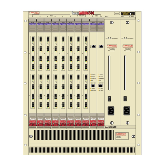
Page 20: Figure 2-1 Smartswitch 6500 Chassis
Receiving Your SmartSwitch 6500 Switch Installation Figure 2-1 SmartSwitch 6500 chassis 2-2 SmartSwitch 6500 Installation and Setup Guide... -
Page 21: Unpacking Your Order
2.1.2 Unpacking Your Order Carefully unpack each component of the SmartSwitch 6500 (chassis, TSMs, CSM, and so on). Inspect each component for damage. Do not attempt to install damaged components. Contact the Cabletron Systems Global Contact Center immediately (see Appendix C, "Technical Support") Inspect the TSMs. -
Page 22: Accessory Carton Contents
— Console cabling instruction sheet — CDROM containing the following: SmartSwitch 6500 operating firmware SmartSwitch ATM switch documentation in Adobe Acrobat format SmartSwitch ATM Administrator software MIB files SmartSwitch 6500 Release Notes 2-4 SmartSwitch 6500 Installation and Setup Guide Switch Installation... -
Page 23: Switch Installation And Assembly
If any of these items are missing, contact Cabletron Global Support Center Note immediately. SWITCH INSTALLATION AND ASSEMBLY The following is a list of steps for assembling your SmartSwitch 6500. Refer to Figure 2-7 for proper module placement. 2.2.1 Mounting the Chassis Find someone to assist you. -
Page 24: Installing The Power Supplies
Remove the metal blank that covers either slot 9 or slot 10 of the chassis (CSMs can reside only in slots 9 and 10). See the legend on the top edge of the SmartSwitch 6500 chassis. Open the ejectors at the top and bottom of the CSM module. -
Page 25: Figure 2-4 Installing Csm In Slot 9
T X D A T A R X D A T A Circuit Card Metal Backpanel Card Guides Figure 2-4 Installing CSM in slot 9 Rotate ejector to lock in place SmartSwitch 6500 Installation and Setup Guide 2-7 Switch Installation and Assembly... -
Page 26: Installing The Tsm With Cpu Daughter Boards
Remove the metal blank that covers either slot 7 or slot 8 of the chassis (TSMs with CPU daughter cards can reside only in slots 7 and 8). See the legend on the top edge of the SmartSwitch 6500 chassis. -
Page 27: Figure 2-6 Installing A Tsm/Cpu Module In Slot 8
Switch Installation Switch Installation and Assembly Rotate ejector to lock in place Circuit Card Metal Backpanel Card Guides Figure 2-6 Installing a TSM/CPU module in slot 8 SmartSwitch 6500 Installation and Setup Guide 2-9... -
Page 28: Installing Additional Tsm Modules
Installing Additional TSM Modules TSM modules without CPU daughter boards can be installed in slots 1 through 6. See the legend on the top edge of the SmartSwitch 6500 chassis. Follow these instructions to install additional TSM modules. Caution Do not attempt to insert a TSM module in either slot 9 or slot 10. -
Page 29: Figure 2-7 Module Placement In The Smartswitch 6500 Chassis
FAIL/OK FAIL/MODE FAIL/MODE Figure 2-7 Module placement in the SmartSwitch 6500 chassis Remove the metal blank that covers one of the chassis’ slots. Open the ejectors at the top and bottom of the TSM module. With the ejector labeled 6A-TSM512 at the top, align the top and bottom of the TSM module with the tracks in the slot. -
Page 30: Installing Other Modules In The Smartswitch 6500 Chassis
Installing Other Modules in the SmartSwitch 6500 Chassis If all SmartSwitch 6500 chassis slots are not occupied by TSMs, other Cabletron SmartSwitch double-wide devices can reside within the chassis. For example, if slots are available, the chassis can also contain Ethernet switches, other ATM switches, and so on (see Figure 2-8 for an example). - Page 31 Switch Installation Table 2-2 Module combinations in 6500 chassis Number of double-wide 6000 modules Installed Number of TSM modules that can be installed Switch Installation and Assembly SmartSwitch 6500 Installation and Setup Guide 2-13...
- Page 32 Switch Installation and Assembly Switch Installation 2-14 SmartSwitch 6500 Installation and Setup Guide...
-
Page 33: Configuring The Switch
Initial network configuration makes the SmartSwitch 6500 accessible by the rest of your network. Backup configuration allows you to save and restore (if necessary) switch configurations. This section also explains SmartSwitch 6500 redundancy and the console commands used to configure and control redundancy. - Page 34 Subnet mask • Default router — IP address of router (if any) that exists between the switch and its TFTP server. The following is an example of the initial network configuration session. For the sake of brevity, the start up messages have been abridged.
-
Page 35: Backup Configuration
3.1.2 Backup Configuration Backup configuration consists of setting up the SmartSwitch 6500 to save configuration backup files. The backup configuration file contains all configuration changes made to the switch. For example, the backup file contains ELAN information, port configuration changes, PVCs, filters, and so on. - Page 36 Perform the following steps to configure backup capabilities. On a workstation that can be reached by your SmartSwitch 6500 and is running TFTP server software, create a file under the /tftpboot directory. This file is used as the backup file by the SmartSwitch 6500, and can initially be blank.
-
Page 37: Tsm/Cpu Redundancy
3.1.4 CSM Redundancy The SmartSwitch 6500 can use two CSM modules: one active (master), the other in standby (slave). By default, the CSM in slot 9 is recognized as the master CSM by the master TSM/CPU module. If the master CSM fails, move the COM port and Ethernet port cables to the slave CSM. Remove the failed CSM from the SmartSwitch 6500 chassis and press the reset button. -
Page 38: Using The Console
Ethernet port cables must be physically moved to the new master CSM. USING THE CONSOLE Use the SmartSwitch 6500 console interface to configure and manage your switch. The following is a description of the console interface and its operation. 3.2.1 Port Numbering The SmartSwitch 6500 is capable of containing both physical and virtual ports. - Page 39 ): Show the current values used by a switch-attribute. show display : Start a process on the switch; for example, start the LAN Emulation Configuration Server. start : Restart a process on the switch; for example, restart : Restore the TSM/CPU configuration from its backup file.
-
Page 40: Console Time-Out
The console can be configured to exit if it does not sense a key stroke within a defined length of time. By default, the SmartSwitch 6500 is set to never time out (value = 0). To activate the time-out feature, use the... -
Page 41: Ambiguous Commands
If you enter part of a command, and that part is not unique, the console displays a numbered list of possible matching commands. For example, entering show pnnin “pnnin.” In response, the SmartSwitch 6500 displays a list of the possible commands: — “pnnin” is ambiguous Smart6500 # show pnnin... -
Page 42: Console Help
Using the Console 3.2.6 Console Help The console provides several levels of help for console commands. For example, to list the switch attributes that can be used with a particular operator, enter the word Smart6500 # help add HELP ----... -
Page 43: Atm Administrator
Perform transactions across multiple switches (for example, create an ELAN when the LANE servers are not co-located • List and sort all connections, virtual connections, ports, modules, and other switch information Capabilities that are not available from the SmartSwitch ATM Administrator are Note debugging and tracing. -
Page 44: Figure 4-1 Atm Administrator Physical Topology View
Introduction ATM Administrator Figure 4-1 ATM Administrator physical topology view 4-2 SmartSwitch 6500 Installation and Setup Guide... -
Page 45: Figure 4-2 Atm Administrator Pnni Topology View
ATM Administrator Introduction Figure 4-2 ATM Administrator PNNI topology view SmartSwitch 6500 Installation and Setup Guide 4-3... -
Page 46: Figure 4-3 View Of Individual Switch In Network
Introduction ATM Administrator Figure 4-3 View of individual switch in network 4-4 SmartSwitch 6500 Installation and Setup Guide... -
Page 47: Starting Atm Administrator
ELAN to another, click on the client, drag it to the symbol that represents the other ELAN, and then drop it on top. Privilege Level Administrator Guest (Cannot affect changes.) SmartSwitch 6500 Installation and Setup Guide 4-5 Starting ATM Administrator... -
Page 48: Managing Your Atm Network
MANAGING YOUR ATM NETWORK SmartSwitch ATM Administrator can connect to your ATM switches through either the switch’s Ethernet interface or through a direct ATM connection to one of the ATM switches. In the later case, your NMS workstation must contain an ATM network adapter card. -
Page 49: Figure 4-5 Atm Administrator Connected Through Nms-Specific Elan
Ethernet may pose connectivity challenges. For example, in figure Figure 4-6, two ATM switches are displayed as generic switch icons (gray boxes, identified by the IP address of their LANE client). In this case, each of these generic switches are not connected to the Ethernet network, but are connected to the other switches through ATM only. -
Page 50: Figure 4-6 Switches That Atm Administrator Cannot Reach Through Ethernet
Figure 4-7 is a diagram of the ATM and Ethernet connectivity of the network map shown in Figure 4-6. Notice that the generic switches, 90.1.1.20 (Switch 4) and 90.1.1.24 (Switch 5), are not connected to the Ethernet network. As a result, switches 4 and 5 do not have direct access to the NMS, and the NMS (using an Ethernet connection) does not know how to reach the subnet 90.0.0.0, which is Switches 4 and 5’s ELAN. - Page 51 ATM networks. For instance, in Figure 4-8, after the route is added to the NMS, a route must be added to Switch 4 that specifies Switch 1’s LANE client as the gateway to the Ethernet network. To add the route on Switch 4, use the...
-
Page 52: Accessing Online Help
(see Figure 4-10). From the Help menu, select SmartSwitch ATM Administrator Help Topics. The Help Topics dialog box appears. You have three options for viewing online help: 4-10 SmartSwitch 6500 Installation and Setup Guide Route on NMS specifying 126.231.44.22 as gateway to 90.0.0.0... -
Page 53: Figure 4-10 Atm Administrator Help Topic Dialog Box
Click the Index tab to select from an alphabetical list of help topics. Click the Find tab to search for a particular topic. Figure 4-10 ATM Administrator Help Topic dialog box Managing Your ATM Network SmartSwitch 6500 Installation and Setup Guide 4-11... - Page 54 Managing Your ATM Network ATM Administrator 4-12 SmartSwitch 6500 Installation and Setup Guide...
-
Page 55: Specifications
5 SPECIFICATIONS This chapter contains SmartSwitch 6500 ATM switch module firmware, hardware, technical, and physical specifications. FRONT PANEL Both the CSM and TSM modules display several LED indicator lights. Table 5-1 and Table 5-2 explain the color, state, and meaning of the CSM and TSM indicator lights. Also, see Figure 5-1. -
Page 56: Figure 5-1 Csm And Tsm Leds
ENET TX DATA TX DATA RX DATA RX DATA Ejector Figure 5-1 CSM and TSM LEDs 5-2 SmartSwitch 6500 Installation and Setup Guide Amber Framer is not receiving sync Ejector TSM FAIL / OK CPU FAIL / MODE Console Terminal... -
Page 57: Technical Specifications
Specifications TECHNICAL SPECIFICATIONS This appendix lists the technical specifications for the SmartSwitch 6500 switch. Table 5-3 Hardware Specifications Specification Processor Switching engine Max I/O ports* Port-to-port latency CPU DRAM memory Buffer memory (cells) Flash memory Serial port Ethernet port *On TSM/CPU modules, ports 7b4... - Page 58 34.3 Mbps E-3 nonchannelized BNC, coax Table 5-6 Protocols Standards and Specifications Protocol Signaling ATM routing protocols LAN protocols 5-4 SmartSwitch 6500 Installation and Setup Guide Connector Max. Tx Min. Tx Power power -8 dBm -15 dBm -8 dBm -15 dBm...
- Page 59 AToM MIB (RFC 1695) AToM2 MIB LANE MIB (ATM Forum) ILMI 4.0 MIB (ATM Forum) IP over ATM MIB PNNI MIB SmartSwitch ATM switch MIBs (proprietary) DB-9 Pin DB-9 Description Receive Transmit Ground SmartSwitch 6500 Installation and Setup Guide 5-5 Technical Specifications...
- Page 60 Technical Specifications Specifications 5-6 SmartSwitch 6500 Installation and Setup Guide...
-
Page 61: Technical Support
APPENDIX A TECHNICAL SUPPORT This appendix tells you what to do if you need technical support for your SmartSwitch 6500 ATM switch. Cabletron offers several support and service programs that provide high-quality support to our customers. For technical support, first contact your place of purchase. If you need additional assistance, contact Cabletron Systems, Inc. There are several easy ways to reach Cabletron Customer Support and Service. -
Page 62: Hardware Warranty
Hardware Warranty • Hardware model number, software version, and switch configuration (that is, what part types are in what slots) HARDWARE WARRANTY Cabletron warrants its products against defects in the physical product for one year from the date of receipt by the end user (as shown by Proof of Purchase).
Need help?
Do you have a question about the SmartSwitch 6500 and is the answer not in the manual?
Questions and answers