
Related Manuals for Cabletron Systems Expansion module 6H122-08


Summary of Contents for Cabletron Systems Expansion module 6H122-08
- Page 1 6H122-08 SmartSwitch 6000 Interface Module User’s Guide 9032159-02 FAST ENET 6H122-08 RESET 100 Mbs...
-
Page 3: Smartswitch
Printed in the United States of America Order Number: 9032159-02 August 1998 Cabletron Systems is a registered trademark and SmartSwitch is a trademark of Cabletron Systems, Inc. All other product names mentioned in this manual may be trademarks or registered trademarks of their respective companies. -
Page 4: Industry Canada Notice
IMPORTANT: Before utilizing this product, carefully read this License Agreement. This document is an agreement between you, the end user, and Cabletron Systems, Inc. (“Cabletron”) that sets forth your rights and obligations with respect to the Cabletron software program (the “Program”) contained in this package. - Page 5 Government is subject to restrictions as set forth in subparagraph (c) (1) (ii) of the Rights in Technical Data and Computer Software clause at 252.227-7013. Cabletron Systems, Inc., 35 Industrial Way, Rochester, New Hampshire 03867-0505. 6H122-08 User’s Guide...
-
Page 6: Declaration Of Conformity
Principal Compliance Engineer ___________________________________ Title Rochester, NH, USA ___________________________________ Location 89/336/EEC 73/23/EEC Cabletron Systems, Inc. 35 Industrial Way PO Box 5005 Rochester, NH 03867 Mr. J. Solari Cabletron Systems Limited Nexus House, Newbury Business Park London Road, Newbury Berkshire RG13 2PZ, England... -
Page 7: Table Of Contents
CHAPTER 1 INTRODUCTION Using This Guide ... 1-1 Structure of This Guide... 1-1 6H122-08 Overview... 1-4 1.3.1 Auto-Negotiation ... 1-4 1.3.2 Connectivity ... 1-4 1.3.3 Full Duplex Switched Ethernet (FDSE)... 1-5 1.3.4 Management ... 1-5 1.3.5 Switching Options ... 1-5 1.3.6 Standards Compatibility ... - Page 8 Contents Connecting to the Network...3-5 3.5.1 Connecting Twisted Pair Cables to Ports 1 Through 6 ...3-5 3.5.2 Connecting a Twisted Pair Segment to the FE-100TX...3-7 3.5.3 Connecting a Fiber Optic Segment to the FE-100FX and FE-100F3 ...3-9 Completing the Installation...3-11 CHAPTER 4 TROUBLESHOOTING Using LANVIEW...4-1...
- Page 9 5.16.1 Establishing Community Names ... 5-57 5.17 SNMP Traps Screen... 5-58 5.17.1 Configuring the Trap Table ... 5-59 5.18 Switch Configuration Screen ... 5-60 5.18.1 Setting the STA... 5-62 5.18.2 Setting the Age Time ... 5-63 5.18.3 Setting (Enabling or Disabling) the Port Status ... 5-63 5.19 Ethernet Interface Configuration...
- Page 10 5.23.1 Changing Source and Destination Ports ...5-80 5.24 Broadcast Suppression Screen ...5-81 5.24.1 Setting the Threshold ...5-82 5.24.2 Setting the Reset Peak Switch ...5-83 5.25 Module Statistics Menu Screen ...5-83 5.26 Switch Statistics Screen...5-85 5.26.1 Using the Clear Counters Command ...5-86 5.27 The Interface Statistics Screen ...5-87...
-
Page 11: Chapter 1 Introduction
Welcome to the Cabletron Systems 6H122-08 SmartSwitch 6000 Interface Module User’s Guide. This guide describes the 6H122-08 Interface Module and provides information concerning network requirements, installation, troubleshooting, and the use of Local Management. USING THIS GUIDE Read through this guide completely to understand the 6H122-08 module features, capabilities, and Local Management functions. - Page 12 FE-100TX pinouts and information concerning cable types used with the FE-100FX and FE100-F3. Appendix Optional Installations and Mode Switch Bank describes how to install optional Fast Ethernet Interface Modules and how to set the Mode Switches. Specifications, Settings, 6H122-08 User’s Guide...
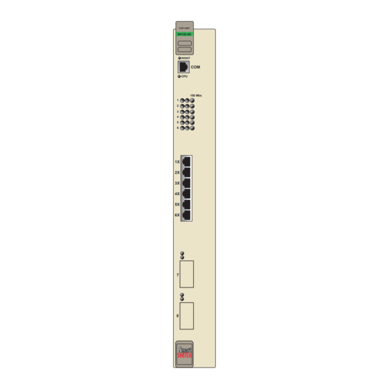
- Page 13 Port Status LEDs Network Ports 1-6 Optional Fast Ethernet Module Ports 7 and 8 6H122-08 User’s Guide FAST ENET 6H122-08 Reset Button COM Port System LED Figure 1-1 The 6H122-08 Structure of This Guide RESET 100 Mbs 2159-01...
-
Page 14: 6H122-08 Overview
Chapter 1: Introduction 6H122-08 OVERVIEW The 6H122-08 is a Fast Ethernet interface module for Cabletron Systems 6C105 chassis that has six RJ45 switched ports and two optional Fast Ethernet Interface Module ports (100BASE-TX and 100BASE-FX) that provide Twisted Pair, Multimode, and Single Mode Fiber Optic cabling connectivity. -
Page 15: Full Duplex Switched Ethernet (Fdse)
MIBs including RFC 1213 (MIB II), RFC 1757 (RMON), RFC 1493 (Bridge MIB) and RFC 1354 (FIB MIB). A full suite of Cabletron Systems Enterprise MIBs provide a wide array of statistical information to enhance troubleshooting. -
Page 16: Lanview Diagnostic Leds
Chapter 1: Introduction 1.3.7 LANVIEW Diagnostic LEDs LANVIEW diagnostic LEDs serve as an important troubleshooting aid by providing an easy way to observe the status of individual ports and overall network operations. Chapter 4 LANVIEW LEDs. 1.3.8 Year 2000 Compliant The 6H122-08 module and 6C105 chassis have an internal clock that can maintain the current time and date beyond the year 1999. -
Page 17: Local Management Features
Statistics, Alarms, Events and History. These groups are enabled on all ports by default. Cabletron Systems RMON Actions is a vendor specific extension of RMON and provides the ability to set an “Action” on any SNMP MIB variable. The Action can be triggered by any RMON Event and/or Alarm. -
Page 18: Port Redirect Function
All purchased bandwidth is used. • Distributed, resilient links increase reliability and performance. • Multiple technologies are supported within a single trunk for maximum flexibility. For more information about SmartTrunk, refer to the Cabletron Systems SmartTrunk User’s Guide. 6H122-08 User’s Guide... -
Page 19: Additional Local Management Functions
1.4.6 Additional Local Management Functions Local Management also allows the following tasks to be performed: • Manage any module installed in the 6C105 via a single terminal connection. • Assign an IP address and subnet mask to the 6H122-08 and 6C105 chassis. -
Page 20: Document Conventions
Chapter 1: Introduction DOCUMENT CONVENTIONS The following conventions are used throughout this document: Note symbol. Calls the reader’s attention to any item of NOTE information that may be of special importance. Tip symbol. Conveys helpful hints concerning procedures or actions. Caution symbol. -
Page 21: Getting Help
Cabletron Systems Technical Writing Department via the following email address: TechWriting@ctron.com Make sure to include the document Part Number in the email message. Before calling the Cabletron Systems Global Call Center, have the following information ready: • Your Cabletron Systems service contract number •... -
Page 22: Related Manuals
These manuals can be obtained from the World Wide Web in Adobe Acrobat Portable Document Format (PDF) at the following site: http://www.cabletron.com/ All documentation for the Cabletron Systems SecureFast VLAN NOTE Manager software is contained on the VLAN Manager CD-ROM. -
Page 23: Chapter 2 Network Requirements
10BASE-T NETWORK When connecting a 10BASE-T segment to any of the 6H122-08 ports, ensure that the network meets the Ethernet network requirements of the IEEE 802.3 standard for 10BASE-T. Refer to the Cabletron Systems Cabling Guide for details. 6H122-08 User’s Guide CHAPTER 2 2.1) -
Page 24: 100Base-Tx Network
100BASE-FX FIBER OPTIC NETWORK Ports 7 and 8 of the 6H122-08 support the Cabletron Systems FE-100FX and FE-100F3 fiber optic interface modules. The device at the other end of the fiber optic segment must meet the 100BASE-FX Fast Ethernet network requirements to operate at 100 Mbps. -
Page 25: Chapter 3 Installation
Only qualified personnel should install the 6H122-08. This chapter covers the following items: • Unpacking the 6H122-08 • Installing options • Installing the 6H122-08 into the 6C105 chassis • Connecting to the network • Completing the installation REQUIRED TOOLS A Phillips screwdriver is required to install the Fast Ethernet Interface Modules in the 6H122-08. -
Page 26: Installing Options
Chapter 3: Installation INSTALLING OPTIONS Install any optional equipment before proceeding to NOTE Section 3.4. If the 6H122-08 will be installed with an optional Fast Ethernet Interface Module refer to Appendix C INSTALLING THE 6H122-08 INTO THE 6C105 CHASSIS Failure to observe static safety precautions could cause damage to the 6H122-08. - Page 27 Observe all precautions to prevent damage from Electrostatic Discharge (ESD). Examine the module for damage. If any damage exists, DO NOT install the module. Immediately contact the Cabletron Systems Global Call Center. To prevent damaging the backplane connectors in the following...
- Page 28 Chapter 3: Installation Slot Number Metal Back-Panel Figure 3-1 Installing an Interface Module FAST ENET 6E122-08 RESET 100 Mbs Circuit Card Card Guides Plastic Locking Tab 2159-01 2159-02 Plastic Locking Tab 6H122-08 User’s Guide...
-
Page 29: Connecting To The Network
CONNECTING TO THE NETWORK This section provides the procedures for connecting Twisted Pair and fiber optic segments from the network or other devices to the 6H122-08. Ports 1 through 6 on the 6H122-08 have RJ45 connectors for Twisted Pair connections. Ports 7 and 8 support FE-100TX, FE-100FX, or FE-100F3 Fast Ethernet Interface Modules. - Page 30 Chapter 3: Installation RX (Receive) LED Column Figure 3-2 6H122-08 Twisted Pair Connection Verify that a link exists by checking that the port RX LED is ON (flashing amber, blinking green, or solid green). If the RX LED is OFF and the TX LED is not blinking amber, perform the following steps until it is on: Verify that the device at the other end of the Twisted Pair segment...
-
Page 31: Connecting A Twisted Pair Segment To The Fe-100Tx
Cabletron Systems Cabling Guide. Refer to Section obtaining this document. If a link is not established, contact the Cabletron Systems Global Call Center. Refer to Section Repeat steps 1 through 3 above, until all connections have been made. - Page 32 Cabletron Systems Cabling Guide. Refer to Section obtaining this document. Confirm that the crossover switch is in the correct position. If a link is not established, contact the Cabletron Systems Global Call Center. Refer to Section FE-100TX 1.8,...
-
Page 33: Connecting A Fiber Optic Segment To The Fe-100Fx And Fe-100F3
FE-100FX and FE-100F3 The FE-100FX and FE-100F3 have an SC style network port (see Figure 3-5). Cabletron Systems supplies fiber optic cable that uses SC style connectors that are keyed to ensure proper crossing over of the transmit and receive fibers. - Page 34 Verify that the fiber connection meets the dB loss specifications outlined in the Cabletron Systems Cabling Guide. If a link has not been established, contact the Cabletron Systems Global Call Center. Refer to Section...
-
Page 35: Completing The Installation
Completing the Installation COMPLETING THE INSTALLATION After installing the 6H122-08 and any optional Fast Ethernet Interface Modules the module is now ready to be set up through Local Management. Refer to Chapter 5 to configure the module and 6C105 chassis. 6H122-08 User’s Guide 3-11... - Page 36 Chapter 3: Installation 3-12 6H122-08 User’s Guide...
-
Page 37: Chapter 4 Troubleshooting
Troubleshooting network and module operational problems • Using the RESET button USING LANVIEW The 6H122-08 uses Cabletron Systems built-in visual diagnostic and status monitoring system called LANVIEW. The LANVIEW LEDs (Figure 4-1) allow quick observation of the network status to aid in the diagnosing of network problems. - Page 38 Chapter 4: Troubleshooting CPU LED Receive (RX) Transmit (TX) Receive (RX) Transmit (TX) FAST ENET 6H122-08 RESET 100 Mbps Figure 4-1 LANVIEW LEDs 10/100 Mbps Operation 2159-07 6H122-08 User’s Guide...
- Page 39 Color Amber Green Amber Green Green Amber 6H122-08 User’s Guide Table 4-1 LANVIEW LEDs State Power off. Blinking. Hardware failure has occurred. Solid. Resetting, normal power up reset. Blinking. Crippled. Solid. Testing. Solid. Functional. Booting. Blinks amber and green while booting.
-
Page 40: Fe-100Tx Led
Recommended Action No action. No action. Port may be disabled due to Spanning Tree. Check network design and eliminate any unnecessary loops. No action. Contact Cabletron Systems Global Call Center for assistance. 6H122-08 User’s Guide... - Page 41 100 LED Receive (RX) LED A link exists if the associated port (port 7 or 8) Receive (RX) NOTE LED is on. No link exists if the associated port (port 7 or 8) Receive (RX) LED is off. Table 4-3 FE-100TX LED Indications Color 10/100 Green...
-
Page 42: Troubleshooting Checklist
Refer to Section 5.15.1 IP address assignment procedure. Enable port. Check link to device. Review network design and delete unnecessary loops. Reenter the lost parameters as necessary. Call the Cabletron Systems Global Cal Center if problem continues. 6H122-08 User’s Guide... -
Page 43: Using The Reset Button
USING THE RESET BUTTON The RESET button located near the upper plastic locking tab of the module (refer to Figure 4-3) resets the 6H122-08 processor without affecting the NVRAM. Pressing the RESET button resets the device, and all current switching being performed by the module is halted. A module CAUTION downtime of up to two minutes will result from this action. - Page 44 Chapter 4: Troubleshooting 6H122-08 User’s Guide...
-
Page 45: Chapter 5 Local Management
6H122-08 module, and the 6C105 chassis. • Monitor the environmental status of the 6C105 chassis. • View switch, interface, and RMON statistics. • Assign ports to operate in standard or full duplex mode. • Enable trunking of ports to perform load sharing. -
Page 46: Local Management Keyboard Conventions
Chapter 5: Local Management LOCAL MANAGEMENT KEYBOARD CONVENTIONS All key names appear as capital letters in this manual. the keyboard conventions and the key functions that are used. Table 5-1 Keyboard Conventions ENTER Key RETURN Key ESCAPE (ESC) Key SPACE bar BACKSPACE Key Arrow Keys [–] Key... -
Page 47: Management Terminal Setup
MANAGEMENT TERMINAL SETUP Use one of the following systems to access Local Management: • An IBM or compatible PC running a VT series emulation software package • A Digital Equipment Corporation VT100 type terminal • A VT type terminal running emulation programs for the Digital Equipment Corporation VT100 series •... - Page 48 Chapter 5: Local Management RJ45 COM Port UTP Cable with RJ45 Connectors RJ45-to-DB9 PC Adapter to PC Figure 5-1 Management Terminal Connection ETHERNET 6E122-08 RESET 100 Mbs 2159-10 FAST ENET 6H122-08 RESET 100 Mbs 6H122-08 User’s Guide...
-
Page 49: Connecting An Uninterruptible Power Supply
Connect the RJ45 connector at one end of the cable to the COM port on the 6H122-08. Plug the RJ45 connector at the other end of the cable into the RJ45-to-DB9 male (UPS) adapter, Cabletron Systems Part No. 9372066. Connect the RJ45-to-DB9 male (UPS) adapter to the female DB9 port on the rear of the UPS device (refer to the particular UPS device’s user... - Page 50 Chapter 5: Local Management RJ45 COM Port UTP Cable with RJ45 Connectors RJ45-to-DB9 PC Adapter Figure 5-2 Uninterruptible Power Supply (UPS) ETHERNET 6E122-08 RESET 100 Mbs 2159-10 DB9 Port FAST ENET 6H122-08 RESET 100 Mbs UPS Device 6H122-08 User’s Guide...
-
Page 51: Management Terminal Setup Parameters
5.3.3 Management Terminal Setup Parameters Table 5-2 lists the setup parameters for the local management terminal. Display Setup Menu Columns -> Controls -> Auto Wrap -> Scroll -> Text Cursor -> Cursor Style -> General Setup Menu Mode -> ID number -> Cursor Keys ->... - Page 52 Chapter 5: Local Management Telnet Connections Once the module or chassis has a valid IP address, the user can establish a Telnet session with Local Management from any TCP/IP based node on the network. Telnet connections to the 6H122-08 require the community name passwords assigned at the SNMP Community Names screen of either the 6C105 chassis, or the module.
-
Page 53: Accessing Local Management
Refer to Section 5.8. 6H122-08 User’s Guide Accessing Local Management Section 5.8. The following steps describe the 6C105 LOCAL MANAGEMENT CABLETRON Systems, Incorporated P.O.Box 5005 Rochester, NH 03866-5005 USA (603) 332-9400 (c) Copyright CABLETRON Systems, Inc, 1997 Enter Password: 2159-12... -
Page 54: Navigating Local Management Screens
802.1D SWITCHING (IEEE 802.1D switching) • 802.1Q SWITCHING (802.1Q port based VLANs) • SECURE FAST VLAN (Cabletron Systems SecureFast Switching) Refer to the Release Notes shipped with the product to verify NOTE which screens are supported in each of the three available switching modes. - Page 55 SNMP Community Names SNMP Traps Chassis Environmental Port Redirect Function Module General Configuration Configuration SNMP Community Names Menu SNMP Traps Switch Configuration Ethernet Interface Configuration SmartTrunk Configuration Module Specific Configuration Menu Switch Statistics Module Interface Statistics Statistics RMON Statistics Menu...
-
Page 56: Selecting Local Management Menu Screen Items
Chapter 5: Local Management Chassis Menu Password Main Menu Module Menu Figure 5-6 SecureFast VLAN Mode, LM Screen Hierarchy 5.4.2 Selecting Local Management Menu Screen Items Select items on a menu screen by performing the following steps: Use the arrow keys to highlight a menu item. Press ENTER. - Page 57 Using the Return Command To exit a Local Management using the RETURN command, proceed as follows: Use the arrow keys to highlight the RETURN command at the bottom of the Local Management screen. Press ENTER. The previous screen in the Local Management hierarchy displays.
-
Page 58: The Main Menu Screen
Chapter 5: Local Management THE MAIN MENU SCREEN The Main Menu Screen is the access point for all Local Management screens for the module and the 6C105 chassis. Menu screen. The following explains each Main Menu screen selection as shown in Figure 5-7: CHASSIS... -
Page 59: Chassis Menu Screen
MODULES The MODULES menu item provides access to the Module Selection screen that is used to select individual modules in the chassis for management purposes. Access the Module Selection screen by using the arrow keys to highlight the MODULES menu item and pressing ENTER. The Module Selection screen displays. -
Page 60: Chassis Configuration Screen
This menu item will only display if one or more modules installed the chassis have been configured to operate as IEEE 802.1Q switches. When selected, this menu item opens the VLAN Main Menu screen. For details, refer to the Cabletron Systems Port Based VLAN User’s Guide. Section 5.7.7,... - Page 61 Access the Chassis Configuration screen from the Chassis Menu screen by using the arrow keys to highlight the CHASSIS CONFIGURATION menu item and pressing ENTER. The Chassis Configuration screen, Figure 5-9, displays. Event Message Line MAC Address: IP Address: Subnet Mask: Operational Mode: [802.1D SWITCHING] SAVE Figure 5-9 Chassis Configuration Screen...
- Page 62 Chapter 5: Local Management Subnet Mask (Modifiable) When a valid IP address is assigned, the Subnet Mask field NOTE automatically enters the default mask that corresponds with class of IP entered in the IP Address field. Some firmware revisions do support changing the chassis subnet mask from the default value.
-
Page 63: Setting The Ip Address
Fast Ethernet Interface Module are bridged to each other. When the operational mode is set to 802.1Q SWITCHING, the 6H122-08 acts as an IEEE 802.1Q switch. The module is able to increase its switching functionality by creating and maintaining port based Virtual LANs (VLANs). -
Page 64: Setting The Subnet Mask
Chapter 5: Local Management Press ENTER. If the IP address is a valid format, the cursor returns to the beginning of the IP address field. If the entry is not valid, the Event Message Line displays “INVALID IP ADDRESS OR FORMAT ENTERED”. -
Page 65: Setting The Chassis Date
5.7.3 Setting the Chassis Date The 6C105 is year 2000 compliant, so the Chassis Date may be set beyond the year 1999. To set the chassis date, perform the following steps: Use the arrow keys to highlight the Chassis Date field. Enter the date in an MM/DD/YYYY format. -
Page 66: Entering A New Screen Refresh Time
Chapter 5: Local Management Use the arrow keys to highlight the SAVE command at the bottom of the screen and press ENTER. If the time entered is a valid format, the Event Message Line at the top of the screen displays “SAVED OK”. If the entry is not valid, Local Management does not alter the current value and refreshes the Chassis Time field with the previous value. -
Page 67: Setting The Operational Mode
If the time entered is within the 1 to 30 minutes range, the Event Message Line at the top of the screen displays “SAVED OK”. If the entry is not valid, Local Management does not alter the current setting, but it does refresh the Screen Lockout Time field with the previous value. -
Page 68: Snmp Community Names Screen
Chapter 5: Local Management If the 6H122-08 has been set to 802.1Q SWITCHING, refer to NOTE your Port Based VLAN User’s Guide to configure the devices for this type of operation. The Operational Mode field in the Chassis Configuration screen does not support the SECURE FAST VLAN operational mode. - Page 69 Event Message Line SAVE Figure 5-11 The SNMP Community Names Screen The following explains each SNMP Community Names screen field: Community Name (Modifiable) Displays the user-defined name through which a user accesses 6C105 management. Any community name assigned here acts as a password to Local/Remote Management.
-
Page 70: Establishing Community Names
Chapter 5: Local Management super-user 5.8.1 Establishing Community Names The password used to access Local Management at the Password screen must have Super-User access in order to view and edit the SNMP Community Names screen. Using a password with read-only or read-write access does not allow the user to view or edit the SNMP Community Names screen. -
Page 71: Snmp Traps Screen
SNMP TRAPS SCREEN Since the 6C105 is an SNMP compliant device, it can send messages to multiple Network Management Stations to alert users of status changes. The SNMP Traps screen is shown in Access the SNMP Traps screen from the Chassis Menu screen by using the arrow keys to highlight the SNMP TRAPS menu item and pressing ENTER. -
Page 72: Configuring The Trap Table
Chapter 5: Local Management Enable Traps (Toggle) Enables transmission of the traps to the network management station with the associated IP address. This field toggles between YES and NO. 5.9.1 Configuring the Trap Table To configure the Trap table, proceed as follows: Using the arrow keys, highlight the appropriate Trap Destination field. -
Page 73: Chassis Environmental Screen
5.10 CHASSIS ENVIRONMENTAL SCREEN The Chassis Environmental menu item allows the user to view chassis environmental information. Access the Chassis Environmental Information screen from the Chassis Menu screen by using the arrow keys to highlight the CHASSIS ENVIRONMENTAL menu item and pressing ENTER. The Chassis Environmental Information screen, Event Message Line Chassis Power Redundancy... -
Page 74: Port Redirect Function Screen
Chapter 5: Local Management 5.11 PORT REDIRECT FUNCTION SCREEN The Port Redirect Function screen may not be available NOTE depending on the operational mode that has been set for the chassis. Refer to your Release Notes to see what operational modes support the Port Redirect Function. - Page 75 Event Message Line Source ============ Module Source Port Source Module [1] SAVE EXIT Figure 5-14 Port Redirect Function Screen The following definitions briefly explain each field of the Port Redirect Function screen. Source Module (Read-Only) Displays which modules are currently set as source modules. Source Port (Read-Only) Displays which ports are currently set as source ports.
-
Page 76: Displaying The Source And Destination Entries
Chapter 5: Local Management Source Port [ n ] (Selectable) Allows a selected port [n] to be configured as a source port. Destination Module [ n ] (Selectable) Allows a selected module [n] to be configured as a destination module. Destination Port [ n ] (Selectable) Allows a selected port [n] to be configured as a destination port. -
Page 77: Changing Source And Destination Ports
5.11.2 Changing Source and Destination Ports Add or delete source/destination module and port entries as follows: Use the arrow keys to highlight the Source Module field. Press the SPACE bar or BACKSPACE one or more times to increment or decrement the module number displayed in the brackets [n] until the appropriate module number is displayed. -
Page 78: Module Selection Screen
Chapter 5: Local Management 5.12 MODULE SELECTION SCREEN The Module Selection screen is the access point to Local Management for all modules installed in the SmartSwitch 6000 chassis. By selecting a module, the Module Menu for the selected device displays. shows the Module Selection screen. -
Page 79: Selecting A Module
Serial # (Read-only) Indicates the serial number of the module. The serial number of the device is necessary when calling the Cabletron Systems Global Call Center. Hardware Revision (Read-only) Reflects the hardware version of the module. 5.12.1 Selecting a Module... -
Page 80: Module Menu Screen
Chapter 5: Local Management 5.13 MODULE MENU SCREEN The Module Menu screen is the access point for all Local Management screens for the 6H122-08. Menu screen. Module Type: 6H122-08 Slot Number: X Figure 5-16 Module Menu Screen The following explains each Module Menu screen field as shown in Figure 5-16: MODULE CONFIGURATION... -
Page 81: Module Statistics
The Module Configuration Menu screen, Local Management screens that allow you to configure and monitor operating parameters, modify SNMP community names, set SNMP traps, configure switch parameters and configure 6H122-08 ports. The following menu items on the Module Configuration Menu NOTE... -
Page 82: General Configuration
For details, refer to 5-38 6H122-08 LOCAL MANAGEMENT Module Configuration Menu Firmware Revision: BOOTPROM Revision: XX.XX.XX GENERAL CONFIGURATION SNMP COMMUNITY NAMES SNMP TRAPS SWITCH CONFIGURATION ETHERNET INTERFACE CONFIGURATION SMARTTRUNK CONFIGURATION MODULE SPECIFIC CONFIGURATION EXIT Section 5.17. XX.XX.XX RETURN 2159-15 Section 5.16. - Page 83 Module Configuration Menu Screen SWITCH CONFIGURATION The Switch Configuration screen provides basic setup options for modifying the switching functions of the modules. For details, refer to Section 5.18. ETHERNET INTERFACE CONFIGURATION The Ethernet Interface Configuration screen indicates the link status, current and desired operational mode, and advertised ability for ports 1 through 8 on the 6H122-08.
-
Page 84: General Configuration Screen
Chapter 5: Local Management 5.15 GENERAL CONFIGURATION SCREEN The General Configuration screen, system date and time, IP address and subnet mask, the default gateway, the TFTP Gateway IP address, the Operational Mode, the Management Mode, and the COM port configuration. The General Configuration screen also allows the user to Clear NVRAM, and enable or disable IP Fragmentation. - Page 85 General Configuration Screen IP Address (Modifiable) This field allows the IP address to be set for the 6H122-08. To set the IP address, refer to Section 5.15.1. Subnet Mask (Modifiable) Displays the subnet mask for the module. A subnet mask “masks out” the network bits of the IP address by setting the bits in the mask to 1 when the network treats the corresponding bits in the IP address as part of the network or subnetwork address, or to 0 if the corresponding bit identifies...
- Page 86 VLANs. When the operational mode is set to SECURE FAST VLAN, the 6H122-08 acts as a SecureFast switch. With the Cabletron Systems VLAN Manager software, the module is able to increase its switching functionality by creating and maintaining Virtual LANs (VLANs).
- Page 87 Management Mode (Toggle) This field toggles between DISTRIBUTED and STAND ALONE. In DISTRIBUTED mode, Local Management is entered via the 6C105 password screen, and all chassis configuration screens are available to the user. All other modules installed in the chassis that are set for distributed management may also be accessed via a connection to a single COM port on one of the modules.
-
Page 88: Setting The Ip Address
Chapter 5: Local Management Clear NVRAM (Toggle) This allows the user to reset NVRAM to the factory default settings. All user-entered parameters, such as IP address and Community Names are then replaced with 6H122-08 default configuration settings. For details, refer to Section 5.15.13. -
Page 89: Setting The Subnet Mask
YOU HAVE ELECTED TO SAVE ONE OR MORE CONFIGURATION ITEMS THAT REQUIRE RESETTING THIS MODULE. ARE YOU SURE YOU WANT TO CONTINUE? Figure 5-19 Configuration Warning Screen Use the arrow keys to highlight the YES command. Press ENTER. The changes are saved and the module reboots. 5.15.2 Setting the Subnet Mask If the management workstation that is to receive SNMP traps from the 6H122-08 is located on a separate subnet, the subnet mask for the... -
Page 90: Setting The Default Gateway
Chapter 5: Local Management Use the arrow keys to highlight the SAVE command, then press ENTER. The warning screen shown in Use the arrow keys to highlight the YES command and press ENTER. The changes are saved and the module reboots. 5.15.3 Setting the Default Gateway If the SNMP management station is located on a different IP subnet than the 6H122-08, a default gateway must be specified. -
Page 91: Setting The Module Date
Press ENTER. If the TFTP gateway IP address entered is a valid format, the cursor returns to the beginning of the TFTP Gateway IP Address field. If the entry is not valid, the Event Message Line displays “INVALID TFTP GATEWAY IP ADDRESS OR FORMAT ENTERED”. -
Page 92: Setting The Module Time
Chapter 5: Local Management 5.15.6 Setting the Module Time To set the module clock, perform the following steps: If the 6C105 chassis has been assigned a chassis time, it is not NOTE necessary to assign a module time to the 6H122-08. All installed modules recognize the chassis time of the 6C105. -
Page 93: Setting The Screen Lockout Time
General Configuration screen, and the module will no longer support Chassis configuration and Module selection screens. If the module will be a SecureFast switch, distributed management is not allowed. The module has been assigned SNMP community names from... -
Page 94: Setting The Management Mode
Chapter 5: Local Management Press the SPACE bar to step to the appropriate operation mode, (802.1D SWITCHING, 802.1Q SWITCHING, or SECURE FAST VLAN). Use the arrow keys to highlight the SAVE command, then press ENTER. The warning screen shown in Use the arrow keys to highlight the YES command and press ENTER. -
Page 95: Configuring The Com Port
5.15.11 Configuring the COM Port Before altering the COM port settings, ensure that a valid IP address is set for the module or chassis. (Refer to CAUTION Section 5.15.1, COM port configuration section before changing the settings of the COM port. The 6H122-08 COM port supports the following applications: Refer to the Release Notes included with the 6H122-08 to NOTE... - Page 96 Chapter 5: Local Management THE COM PORT HAS BEEN RECONFIGURED AND THERE IS NO IP ADDRESS SET FOR THIS DEVICE. YOU WILL NO LONGER BE ABLE TO MANAGE THIS BOARD. DO YOU STILL WISH TO RECONFIGURE THIS COM PORT? Figure 5-20 COM Port Warning Screen If the 6C105 chassis has been configured with a valid IP NOTE address this screen will not appear.
-
Page 97: Changing The Com Port Application
5.15.12 Changing the Com Port Application After enabling the COM port as described in select one of the applications supported by the COM port: LM, and UPS. The default application is LM. To change the COM port application: Use the arrows keys to highlight the Application field. Use the SPACE bar or BACKSPACE to step through the available settings until the operation you require appears. -
Page 98: Clearing Nvram
Chapter 5: Local Management 5.15.13 Clearing NVRAM Clearing NVRAM will result in the loss of all user-entered parameters. Do not proceed unless this procedure is completely understood. CAUTION Clearing NVRAM allows the user to clear all user-entered parameters, such as IP address and Community Names from NVRAM. Clear NVRAM as follows: Use the arrow keys to highlight the Clear NVRAM field. -
Page 99: Enabling/Disabling Ip Fragmentation
5.15.14 Enabling/Disabling IP Fragmentation To enable or disable IP fragmentation, proceed as follows: Use the arrow keys to highlight the IP Fragmentation field. Press the SPACE bar to choose either ENABLED or DISABLED. Use the arrow keys to highlight the SAVE command. Press ENTER. - Page 100 Chapter 5: Local Management Access the SNMP Community Names screen from the Module Configuration Menu screen by using the arrow keys to highlight the SNMP COMMUNITY NAMES menu item and pressing ENTER. The SNMP Community Names screen, Event Message Line Module Type: 6H122-08 Slot Number: X SAVE...
-
Page 101: Establishing Community Names
read-write super-user 5.16.1 Establishing Community Names The password used to access Local Management at the Password Screen must have Super-User access in order to view and edit the SNMP Community Names screen. Using a password with read-only or read-write access does not allow the user to view or edit the SNMP Community Names screen. -
Page 102: Snmp Traps Screen
Chapter 5: Local Management 5.17 SNMP TRAPS SCREEN Since the 6H122-08 is an SNMP compliant device, it can send messages to multiple Network Management Stations to alert users of status changes. The SNMP Traps screen is shown in It is only necessary to assign SNMP traps if the user desires NOTE the traps to be sent to different addresses than those assigned Section 5.8... -
Page 103: Configuring The Trap Table
Trap Community Name (Modifiable) Displays the Community Name included in the trap message sent to the Network Management Station with the associated IP address. Enable Traps (Toggle) Enables transmission of the traps to the network management station with the associated IP address. This field toggles between YES and NO. 5.17.1 Configuring the Trap Table To configure the Trap Table, proceed as follows: Using the arrow keys, highlight the appropriate Trap Destination... -
Page 104: Switch Configuration Screen
The Switch Configuration screen, options to modify switch operations in your network. Access the Switch Configuration screen from the Module Configuration Menu screen by using the arrow keys to highlight the SWITCH CONFIGURATION menu item and pressing ENTER. The Switch Configuration screen, edit the fields for ports 9 to 12, highlight [9-12] at the bottom of the... - Page 105 The module will discard an address from its switch table if it does not receive a valid packet from the applicable address in the amount of time specified in the Age Time field.
-
Page 106: Setting The Sta
Chapter 5: Local Management Port # (Read-Only) Lists each switch port on the module. If the number of ports is greater than eight, then the additional ports are listed on subsequent screens. MAC Address (Read-Only) Displays the hardware address assigned to each listed port. -
Page 107: Setting The Age Time
Use the SPACE bar to toggle to either ENABLED or DISABLED. Use the arrow keys to highlight the SAVE command at the bottom of the screen. Press ENTER. The message “SAVED OK” is displayed. 6H122-08 User’s Guide Switch Configuration Screen 5-63... -
Page 108: Ethernet Interface Configuration
Chapter 5: Local Management 5.19 ETHERNET INTERFACE CONFIGURATION Access the Ethernet Interface Configuration screen from the Module Specific Configuration Menu screen by using the arrow keys to highlight the ETHERNET INTERFACE CONFIGURATION menu item and pressing ENTER. The Ethernet Interface Configuration screen displays. Event Message Line Module Type: 6H122-08 Slot Number: X... - Page 109 Link Status (Read-Only) Indicates whether or not there is a physical connection from a particular port to another 10BASE-T, 100BASE-TX/FX, or 100BASE-TXFD/FXFD device. One of the following values is displayed: • Link – There is a link signal present and a valid physical connection to another 10BASE-T, 100BASE-TX/FX, or 100BASE-TXFD/FXFD device.
-
Page 110: Configuring An Fe-100Tx Interface
Chapter 5: Local Management In normal operation, the port with an FE-100TX installed NOTE automatically establishes a link with the device at the other end of the segment without requiring user setup. However, Local Management provides the user with the option of manually configuring that port. -
Page 111: Setting The Fe-100Tx Advertised Ability
Use the SPACE bar to select the desired mode. Press ENTER. If any mode other than Auto-Negotiation is selected, the port only operates in the chosen mode and auto-negotiation is disabled. Use the arrow keys to highlight the SAVE command. Press ENTER. The message “SAVED OK”... -
Page 112: Configuring An Fe-100Fx Or Fe-100F3 Interface For Port 7 Or 8
Chapter 5: Local Management 5.19.4 Configuring an FE-100FX or FE-100F3 Interface for Port 7 or 8 When an FE-100FX or FE-100F3 is installed in port 7 or 8, it must be manually set to operate in the same technology as the device at the other end of the connected segment. -
Page 113: Module Specific Configuration Menu Screen
5.20 MODULE SPECIFIC CONFIGURATION MENU SCREEN The Module Specific Configuration Menu screen, user to select one of five screens to configure ports or check system resources specific to the 6H122-08. The following menu items on the Module Specific Configuration NOTE Menu screen may not display if the operational mode of the module has been set to SECURE FAST VLAN or 802.1Q SWITCHING:... -
Page 114: System Resources
Chapter 5: Local Management Module Type: 6H122-08 Slot Number: X SAVE Figure 5-26 Module Specific Configuration Menu Screen The following explains each field of the Module Specific Configuration Menu screen: SYSTEM RESOURCES The System Resources screen displays the amount of FLASH memory, DRAM, and NVRAM installed, details how much memory is available and provides information on 6H122-08 operation. -
Page 115: Broadcast Suppression
IEEE 802.1Q switch and the Management Mode has been set to STAND ALONE. When selected, this menu item opens the VLAN Main Menu screen. For details, refer to the Cabletron Systems Port Based VLAN User’s Guide. Section describes how to configure the modules to function as 802.1Q switches. -
Page 116: System Resources Screen
BOOTPROM Revision: XX.XX.XX CPU Type: i960 HT 25Mhz Available: XX MB Available: XX KB Available: Current Switch Utilization: 66% Peak Switch Utilization: 75% Reset Peak Switch Utilization: [NO] EXIT XX.XX.XX XXXXX Bytes XXXXX Bytes XXXXX Bytes RETURN RETURN 2159-40 6H122-08 User’s Guide... -
Page 117: Setting The Reset Peak Utilization
Shows the peak percentage of maximum switching capacity, since last reset. Reset Peak Switch Utilization (Toggle) Allows the user to reset the Peak Switch Utilization field. The switch may be set to either YES or NO as described in Peak Switch Utilization field to the current system traffic. -
Page 118: Flash Download Screen
file from a TFTP server. The user may also force a download by changing the position NOTE of Switch 6 located inside the module. Refer to details. Before downloading a new image to the module, load the image onto the network TFTP server. - Page 119 Download Server IP and Download Server Filename are NOTE displayed only when TFTP or RUNTIME are selected in Download Method. The following briefly explains each field of the Flash Download screen: Download Method (Selectable) This field steps through TFTP, RUNTIME and BOOTP. If set for BOOTP, the module sends out a BootP request to determine the IP address of the TFTP server and the filename of the image to be downloaded.
-
Page 120: Image File Download Using Tftp
Chapter 5: Local Management If TFTP or RUNTIME is selected as the download method (Figure 5-28), the following two additional fields appear: Download Server IP (Selectable) The IP address of the TFTP server to be used for the FLASH download is entered in this field. -
Page 121: Image File Download Using Runtime
5.22.2 Image File Download Using RUNTIME Set the 6H122-08 to download to FLASH using RUNTIME as follows: Use the arrow keys to highlight the Download Method field. Use the SPACE bar to select RUNTIME. Use the arrow keys to highlight the Reboot After Download field. Use the SPACE bar to select either YES or NO. -
Page 122: Port Redirect Function Screen
Chapter 5: Local Management 5.22.3 Image File Download Using BootP Set the 6H122-08 to download to FLASH using BootP as follows: Use the arrow keys to highlight the Download Method field. Use the SPACE bar to select BOOTP. Use the arrow keys to highlight the TFTP Gateway IP Addr field. Set the IP address of the TFTP gateway server (this defaults to the same IP address set in the TFTP Gateway IP Addr field in the General Configuration screen). - Page 123 Access the Port Redirect Function screen from the Module Specific Configuration Menu screen by using the arrow keys to highlight the PORT REDIRECT FUNCTION menu item and pressing ENTER. The Port Redirect Function screen displays. Event Message Line Module Type: 6H122-08 Slot Number: X Source Port: ============...
-
Page 124: Changing Source And Destination Ports
Chapter 5: Local Management Errors (Toggle) Allows the user to configure the source ports to either send errored frames to selected destination ports, or to drop errored frames, and send only valid traffic to the destination ports. The default setting of this field is ON. Status (Toggle) Allows you to add or delete the source and destination ports selected in the Source Port [n] and Destination Port [n] fields. -
Page 125: Broadcast Suppression Screen
5.24 BROADCAST SUPPRESSION SCREEN The Broadcast Suppression screen, desired limit of receive broadcast frames per port per second. The Broadcast Suppression screen may not be available if the NOTE operational mode of the module has been set to SECURE FAST VLAN. Refer to your Release Notes to see what operational modes support Broadcast Suppression. -
Page 126: Setting The Threshold
Chapter 5: Local Management The following explains each field of the Broadcast Statistics screen: PORT # (Read-only) Identifies the number of the port. Total RX (Read-Only) Displays the total number of broadcast frames received. Peak Rate (Read-Only) Displays the number of broadcast frames received per second. Time Since Peak (Read-Only) Displays the time since peak broadcast frames received. -
Page 127: Setting The Reset Peak Switch
5.24.2 Setting the Reset Peak Switch To set the Reset Peak Switch field to YES or NO, proceed as follows: Use the arrow keys to highlight the Reset Peak field for the selected port. Press the SPACE bar to select YES or NO. -
Page 128: Switch Statistics
Figure 5-31 Module Statistics Menu Screen The Module Statistics Menu screen displays the following menu items: SWITCH STATISTICS The Switch Statistics screen lists the number of frames received, transmitted, filtered, and forwarded by each interface. INTERFACE STATISTICS The Interface Statistics screen provides the MIB-II statistics for each switched interface, on an interface-by-interface basis. -
Page 129: Switch Statistics Screen
SECURE FAST VLAN. This screen may only be used by modules configured to operate as traditional or 802.1Q switches. Ports 7 and 8 on the Switch Statistics screen represent the optional Fast Ethernet Interface Modules available for the 6H122-08. -
Page 130: Using The Clear Counters Command
Chapter 5: Local Management The Switch Statistics screen displays the following items: Port # (Read-Only) Identifies the interface or port number. Frames Rcvd (Read-Only) Displays the number of frames received by the interface. Frames Txmtd (Read-Only) Displays the number of frames transmitted by the interface. -
Page 131: The Interface Statistics Screen
5.27 THE INTERFACE STATISTICS SCREEN The Interface Statistics screen is used to gather MIB-II statistics for all of the 6H122-08 interfaces (ports 1 through 6, optional Fast Ethernet Interface Modules and all backplane interfaces). Access the Interface Statistics screen by using the arrow keys to highlight the INTERFACE STATISTICS menu item on the Module Statistics Menu screen and pressing ENTER. - Page 132 The InDiscards field displays the total number of inbound frames that were discarded, even though the frames contained no errors. This field may increment because the switch needed to free up buffer space, or the switch was being overutilized. InErrors (Read-only) This field displays the total number of inbound frames that have been...
- Page 133 The OutDiscards field displays the total number of outbound frames that were discarded, even though the frames contained no errors. This field may increment, because the switch needed to free up buffer space, or the switch was being overutilized. OutErrors (Read-only) This field displays the total number of outbound frames discarded...
-
Page 134: Displaying Interface Statistics
Chapter 5: Local Management Link Status (Read-only) This field displays the current link status of the interface. This field will read either “Link” or “No Link”. Duplex Mode (Read-only) This field indicates whether the interface is operating in normal or full duplex mode. -
Page 135: Rmon Statistics Screen
5.28 RMON STATISTICS SCREEN RMON statistics for each interface, on a interface-by-interface basis, are viewed through the RMON Statistics screen shown in Access the RMON Statistics screen by using the arrow keys to highlight the RMON STATISTICS menu item on the Module Statistics Menu screen and pressing ENTER. - Page 136 Drop Events (Read-only) This field displays the total number of times that the RMON agent was forced to discard frames due to the lack of available switch resources. The Drop Events field does not display the number of frames NOTE dropped, it only displays the number of times that the RMON agent was forced to discard frames.
- Page 137 Multicasts (Read-only) The Multicasts field displays the total number of good frames received that were directed to a multicast address. The value of this field does not include frames directed to the broadcast address. CRC Align Errors (Read-only) This field displays the number of frames with bad Cyclic Redundancy Checks (CRC) received from the network.
- Page 138 Chapter 5: Local Management Total Octets (Read-only) This field displays the total number of octets (bytes) of data, including those in bad frames, received on this interface. 64 Octets (Read-only) Displays the total number of frames including bad frames, received that were 64 bytes in length (excluding framing bits, but including FCS bytes).
-
Page 139: Displaying Rmon Statistics
5.28.1 Displaying RMON Statistics To display the statistics for any index, proceed as follows: Use the arrow keys to highlight the Index [XX] field at the bottom of the screen. Press the SPACE bar to increment (or press the DEL [delete] key to decrement) the index number. -
Page 140: Network Tools
Chapter 5: Local Management 5.29 NETWORK TOOLS The Network Tools function resides on the 6H122-08 and allows the user to access and manage network devices. Access the Network Tools screen by using the arrow keys to highlight the NETWORK TOOLS menu item in the Module Menu screen and pressing ENTER. -
Page 141: Built-In Commands
The conventions used in describing the commands in Network NOTE Tools are as follows: Arguments enclosed by [ ] are required. Arguments enclosed by < > are optional. In the following command examples, the information entered by the user is shown in bold Helvetica font To abort the output or interrupt a process, press the CONTROL key and c key simultaneously, designated as ^C here. -
Page 142: Mac Address
Chapter 5: Local Management You can specify the arp command without options, or with one of the following options: Options: Example: -> arp -a # Interface # (SonicInt) # (SonicInt) # (SonicInt) # (SonicInt) -> arp -d 1 122.144.52.68 -> arp -s 1 22.44.2.3 00:00:0e:03:1d:3c ->... - Page 143 bridge: Syntax: Description: Options: Example: -> bridge disable all -> bridge enable 1 -> bridge disable 1 6H122-08 User’s Guide bridge [ENABLE/DISABLE] [IFNUM/ALL] The bridge command allows each bridge port to be enabled or disabled at the user’s request, either one at a time or all at once. Specifying a single interface number will affect the bridging status of that interface, while specifying ALL will affect every interface.
- Page 144 Chapter 5: Local Management defroute: Syntax: Description: Options: Example: -> defroute 2 147.152.42.32 # Default route is 147.152.42.32 on interface 2 -> defroute # Default route is 147.152.42.32 on interface 2 -> defroute delete # Default route is not currently set. ->...
- Page 145 netstat: Syntax: Description: Options: Example: -> netstat -i Interface + Description # 1 (ethernet -csmacd) # 2 (ethernet - csmacd) # 3 (ethernet - csmacd) # 4 (ethernet - csmacd) -> netstat -r Destination Next-hop # Default Route DirectConnection # 134.141.0.0 DirectConnection # 134.141.0.0 DirectConnection...
- Page 146 Chapter 5: Local Management reset: Syntax: Description: The Network Tools connection to the module will be terminated upon execution of this command. CAUTION Options: Example: -> reset 5-102 reset The reset command allows a soft reset of the device. The user will be queried to confirm the reset command to insure against unwanted resets.
- Page 147 show: Syntax: Description: Options: Example: -> show Appletalk interfaces AdminStatus # Interface enabled disabled -> show IP ARP MediaType # Interface 3 (dynamic) 3 (dynamic) 6H122-08 User’s Guide show [PROTOCOL] [TABLE] The show command displays information concerning various components of the device. Protocols currently supported are IP, IPX, DECnet, and AppleTalk.
- Page 148 Chapter 5: Local Management traceroute: Syntax: Description: Options: Example: -> traceroute 122.144.11.52 # next-hop[0] : 122.144.60.45 # next-hop[1] : 122.144.8.113 # next-hop[2] : 122.144.61.45 # 122.144.11.52 is alive : 3 hops away. soft_reset: Syntax: Description: The Network Tools connection to the module will be terminated upon execution of this command.
- Page 149 telnet: Syntax: Description: Options: Example: 6H122-08 User’s Guide telnet [IP address] [Port #] The telnet command allows the user to communicate with another host (that supports Telnet connections) using the Telnet protocol. The user must specify the remote host using its IP address.
-
Page 150: Special Commands
Chapter 5: Local Management link_trap: Syntax: Description: Options: Example: -> link_trap status LINK TRAP STATUS: Port 1 is ENABLED Port 3 is ENABLED -> link_trap disable 2 Link traps have been DISABLED on port 2 -> link_trap disable all Link traps have been DISABLED on all ports (1-24) ->... -
Page 151: A.3 Environmental Requirements
This appendix provides operating specifications for the Cabletron Systems 6H122-08 Interface Modules. Cabletron Systems reserves the right to change these specifications at any time without notice. DEVICE SPECIFICATIONS Processor: Dynamic Random Access Memory (DRAM): FLASH Memory: PHYSICAL PROPERTIES Dimensions: Weight (Unit):... -
Page 152: Input/Output Ports
Appendix A: Specifications INPUT/OUTPUT PORTS 6H122-08 Specifications Ports 1 through 6 Slots for optional Fast Ethernet Interface Modules (ports 7 and 8) COM PORT PINOUT ASSIGNMENTS The COM port is a serial communications port that supports Local Management or connection to a UPS. The COM port has the following pin assignments: Table A-1 COM Port Pin Assignments Signal Name... -
Page 153: A.6 Regulatory Compliance
Regulatory Compliance REGULATORY COMPLIANCE Safety The 6H122-08 meet the safety requirements of UL 1950, CSA C22.2 No. 950, EN 60950, IEC 950 and 73/23/EEC. Electromagnetic Compatibility (EMC) The 6H122-08 meet the requirements of FCC Part 15, EN 50082-1, EN 55022, VCCI V-3, CSA C108.8, AS/NZS 3548 and 89/336/EEC. 6H122-08 User’s Guide... - Page 154 Appendix A: Specifications 6H122-08 User’s Guide...
-
Page 155: B.1 Fe-100Tx
Unshielded Twisted Pair (UTP) cabling with an impedance between 85 and 111 ohms. The slide switch on the FE-100TX determines the crossover status of the cable pairs. If the switch is on the over. If the switch is on the over. -
Page 156: B.2 Fe-100Fx
Appendix B: FE-100TX, FE-100FX and FE-100F3 Specifications FE-100FX The FE-100FX shown in supports multimode fiber optic cabling. Specifications for the FE-100FX are listed below. Cable Type 50/125 µm fiber 62.5/125 µm fiber 100/140 µm fiber The transmitter power levels and receive sensitivity levels listed NOTE are peak power levels after optical overshoot. -
Page 157: B.3 Fe-100F3
FE-100F3 The FE-100F3 shown in supports single mode fiber optic cabling. Specifications for the FE-100F3 are listed in Table B-2 Cable Type 8/125 µm fiber 12/125 µm fiber The transmitter power levels and receive sensitivity levels listed NOTE are peak power levels after optical overshoot. A peak power meter must be used to correctly compare the values given above to those measured on any particular port. - Page 158 Appendix B: FE-100TX, FE-100FX and FE-100F3 Specifications 6H122-08 User’s Guide...
-
Page 159: C.2 Setting The Mode Switch
OPTIONAL INSTALLATIONS AND MODE SWITCH BANK SETTINGS This appendix covers the following items: • Required tools (Section • Locations, functions, and settings for the mode switches • Installing Optional Fast Ethernet Interface Modules REQUIRED TOOLS You need the following tools to perform the procedures provided in this appendix: •... - Page 160 Figure C-1 6H122-08 Mode Switch Location/Component Layout Switch definitions and positions are as follows: • Switches 1 through 4 – For Cabletron Systems use only. • Switch 5 – COM Port Autobaud. The default (OFF) position enables Autobaud sensing on the COM port for Local Management sessions.
-
Page 161: Setting The Mode Switch
NVRAM, and restores the default passwords. Once the 6H122-08 resets, the passwords can either be reentered or the default passwords (Public and ENTER) may be used. Do not change the position of switch 8 unless it is necessary to NOTE reset the module super-user configured passwords to their factory default settings. -
Page 162: Installing Optional Fast Ethernet Interface Modules
Appendix C: Optional Installations and Mode Switch Bank Settings INSTALLING OPTIONAL FAST ETHERNET INTERFACE MODULES Figure C-2 shows the location of the Fast Ethernet Interface Module connectors on the 6H122-08 board for port slots 7 and 8. Optional Fast Ethernet Interface... - Page 163 Installing Optional Fast Ethernet Interface Modules To install a Fast Ethernet Interface Module in port slot 7 or 8 of the 6H122-08, proceed as follows: The Fast Ethernet Interface Module and the 6H122-08 are sensitive to static discharges. Use an antistatic wrist strap and observe all static precautions during this procedure.
- Page 164 Appendix C: Optional Installations and Mode Switch Bank Settings Coverplate Figure C-3 Coverplate Removal Remove the screw from the rear standoff. Save the screw. When installing an FE-100FX or FE-100F3 module into the 6H122-08, remove the rubber plug on the module before CAUTION proceeding.
- Page 165 Installing Optional Fast Ethernet Interface Modules Figure C-4 Installing the Fast Ethernet Interface Module Press down firmly on the Fast Ethernet Interface Module until the pins slide all the way into the motherboard connector. Ensure that the Fast Ethernet Interface Module seats flush on the standoffs. Secure the Fast Ethernet Interface Module with the screws saved in steps 1 and 2.
- Page 166 Appendix C: Optional Installations and Mode Switch Bank Settings 6H122-08 User’s Guide...
-
Page 167: Index
Clearing NVRAM 5-54 6H122-08 User’s Guide INDEX COM port pin assignments A-2 Connecting to the network 3-5 Current switch utilization 5-73 Default gateway 5-41, 5-46 Device Menu screen 5-36 Displaying statistics 5-90, 5-95 Environmental requirements A-1 Ethernet Interface screen advertised ability 5-66... - Page 168 5-101 ping 5-101 reset 5-102 show 5-103 soft_reset 5-104 telnet 5-105 traceroute 5-104, 5-105 operational mode 5-19 Password screen 5-9 Peak switch utilization 5-73 Physical properties A-1 Port Redirect Function 5-30, 5-70 port redirect function 5-16 6H122-08 User’s Guide...
- Page 169 SNMP Traps screen 5-27, 5-58 Switch Configuration screen 5-60 Switch Statistics screen 5-85 System Resources screen 5-72 Setting communtiy names 5-26 Setting the reset peak switch 5-83 Setting the threshold 5-82 SNMP Community Names screen 5-24, 5-55 access policy 5-25, 5-56...
- Page 170 Index Index-4 6H122-08 User’s Guide...
Need help?
Do you have a question about the Expansion module 6H122-08 and is the answer not in the manual?
Questions and answers