Table of Contents
Advertisement
Quick Links
Download this manual
See also:
Important Notice
Advertisement
Table of Contents

Related Manuals for Cabletron Systems 6C105


Summary of Contents for Cabletron Systems 6C105
- Page 1 6C105 SmartSwitch 6000 Overview and Setup Guide 6C405 9032016-04...
-
Page 3: Fcc Notice
Only qualified personnel should perform installation procedures. Cabletron Systems reserves the right to make changes in specifications and other information contained in this document without prior notice. The reader should in all cases consult Cabletron Systems to determine whether any such changes have been made. -
Page 4: Doc Notice
IMPORTANT: Before utilizing this product, carefully read this License Agreement. This document is an agreement between you, the end user, and Cabletron Systems, Inc. (“Cabletron”) that sets forth your rights and obligations with respect to the Cabletron software program (the “Program”) contained in this package. - Page 5 Government is subject to restrictions as set forth in subparagraph (c) (1) (ii) of the Rights in Technical Data and Computer Software clause at 252.227-7013. Cabletron Systems, Inc., 35 Industrial Way, Rochester, New Hampshire 03867-0505. 6C105 Overview and Setup Guide...
-
Page 6: Declaration Of Conformity
EN 50082-1 EN 60950 Networking Equipment, for use in a Commercial or Light Industrial Environment. Legal Representative in Europe Mr. J. Solari ___________________________________ Full Name Managing Director - E.M.E.A. ___________________________________ Title Newbury, Berkshire, England ___________________________________ Location 6C105 Overview and Setup Guide... -
Page 7: Table Of Contents
Installing a Power Supply Module... 3-6 3.2.6 Installing 6C105 Interface Modules ... 3-9 Powering Up a 6C105 with AC Power Supplies ... 3-11 Powering Up a 6C105 with DC Power Supplies... 3-11 3.4.1 Connecting a 6C205-2 to a 48/60 VDC Power Source. 3-13 Removing and Reinstalling the Fan Tray ... - Page 8 Contents 6C105 Overview and Setup Guide...
-
Page 9: Chapter 1 Introduction
Read through this guide completely to familiarize yourself with its contents and to gain an understanding of the features and capabilities of the 6C105 SmartSwitch 6000. This guide lists the features and options of the 6C105 SmartSwitch 6000 and explains how to remove and reinstall the fan tray, and install the power supply(ies), modules and the cable management bar. -
Page 10: Document Conventions
USING THE 6C105 MANUAL SET Other manuals have been developed for the interface modules that can be installed in the 6C105 chassis. These manuals explain how to install the modules into the 6C105, how to attach cable segments to the modules, and how to configure the modules using Local Management after... -
Page 11: Getting Help
Cabletron Systems Technical Writing Department via the following email address: TechWriting@ctron.com Make sure to include the document Part Number in the email message. Before calling the Cabletron Systems Global Call Center, have the following information ready: • Your Cabletron Systems service contract number •... -
Page 12: Overview
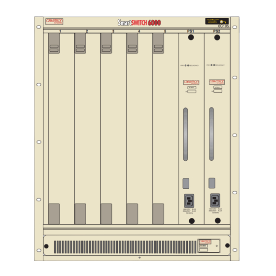
Chapter 1: Introduction OVERVIEW The Cabletron Systems 6C105 chassis design provides five 2.4-inch slots that can contain a variety of interface modules. The chassis supports redundant power supplies, LANVIEW Diagnostic LEDs, and is 19-inch rack mountable. All chassis components (power supplies, fan tray, and modules) are installed from the front of the chassis for ease of maintenance. -
Page 13: Features
DC power source. In addition, the power supply modules are capable of load sharing 50% (+/- 5%) of the total load presented by the 6C105. If one of the power supply modules fails, the other power supply module supplies the entire load of the chassis without interruption to network traffic. - Page 14 The 6C105 Cooling System The 6C105 features a removable fan tray that is accessible from the front of the unit. This unit is hot swappable, which allows it to be replaced without powering down the chassis. The fan tray has one LANVIEW LED located on the front of the unit.
-
Page 15: Chapter 2 Installation Requirements And Specifications
3 inches of clearance above the unit and 2 inches of clearance on either side of the unit. • If the 6C105 is to be placed on a shelving unit, the shelf must be able to support 75 pounds of static weight. •... -
Page 16: Configuration Guidelines
Chapter 2: Installation Requirements and Specifications CONFIGURATION GUIDELINES The 6C105 has 5 slots that accept interface modules. The slots are numbered 1 to 5 beginning from the left. There are two additional slots located on the far right of the chassis that are reserved for power supply modules. -
Page 17: Physical Specifications
2.3.1 Physical Specifications The physical specifications for the 6C105 chassis, 6C205-1, 6C205-2, 6C205-3 power supply modules and the 6C405 fan tray module are as follows: 6C105 Chassis Dimensions: Weight (with factory installed fan tray): 6C205-1 Power Supply Dimensions: Weight: 6C205-2 Power Supply... -
Page 18: Power Supply Requirements
The following sections describe the functions and definitions of the LANVIEW LEDs for the power supply module and the fan tray unit for the 6C105. All three power supplies available for the 6C105 chassis have NOTE the same LEDs. 2.4.1 Power Supply LEDs There are two LEDs on the power supply. - Page 19 REDUNDANCY Green Amber PWR LED Figure 2-1 Power Supply LEDs 6C105 Overview and Setup Guide Status All outputs and input of the power supply are within regulation. Any output or input of the specific power supply is out of regulation.
-
Page 20: Fan Tray Led
Refer to Table 2-2 Fan Tray LED States and Their Definitions LED Color Green When the 6C105 is first powered up, the Fan Tray LED will NOTE display red briefly, until the fans are operating at the proper speed. -
Page 21: 6C105 Setup
This chapter contains instructions on setting up the Cabletron Systems 6C105 chassis. A Phillips screwdriver is needed to install the unit in a 19-inch equipment rack, to install the cable management bar, to secure the power supply module(s) and to remove and reinstall the fan tray. Refer to Chapter 2 for the guidelines that must be followed to install the 6C105. -
Page 22: Setting Up The 6C105
6C105. 3.2.1 Installation Order Once a suitable site has been chosen, the 6C105 can be installed. The chassis can be freestanding or rack mounted. It is recommended that the 6C105 installation proceed in this order: Install the cable management bar. -
Page 23: Installing The Cable Management Bar
Refer to Figure 3-1. Line up the two holes on each side of the cable management bar with the two holes located underneath the 6C105, near the front of the chassis. Using a Phillips screwdriver securely fasten the 4 screws. -
Page 24: Rack Mounting The 6C105
Two people may be required to lift the chassis into place. The chassis is secured with ten screws, five on each side. Using the screws provided with the equipment rack, secure the 6C105 to the rack, starting with the bottom holes and working up, as shown in... -
Page 25: Attaching The Electrostatic Discharge Wrist Strap
Attaching the Electrostatic Discharge Wrist Strap The Electrostatic Discharge (ESD) Wrist Strap must be attached before handling the power supplies, fan tray, or modules for the 6C105. In addition, observe all precautions when handling these modules to prevent damage from ESD. -
Page 26: Installing A Power Supply Module
3.2.5 Installing a Power Supply Module You must install at least one power supply in the 6C105 chassis. One power supply provides sufficient power for most module configurations but a second power supply can be installed to provide a redundant, load sharing power source. - Page 27 With the power supply inserted into the slotted paths, carefully slide the module forward until it is connected to the backplane with the front panel flush with the face of the 6C105. Do not force the module into place. If significant resistance is encountered before the front panel is flush, remove and reinsert the power supply.
- Page 28 Metal Back-Panel Figure 3-4 Installing the Power Supply Module(s) After installation of the power supply modules is completed the 6C105 is ready to be powered up; however, Cabletron Systems recommends that installation of all modules for the 6C105 be completed before powering up the 6C105.
-
Page 29: Installing 6C105 Interface Modules
3.2.6 Installing 6C105 Interface Modules The 6C105 Interface Modules can be installed in any of the 5 slots that are available. To install a module, proceed as follows: Remove the blank panel covering the slot in which the Interface Module will be installed. All other slots must remain covered to ensure proper airflow and cooling. - Page 30 Chapter 3: 6C105 Setup Metal Back-Panel Figure 3-5 Installing a Module 3-10 Slot Number Backplane Connector Fast Enet 6E252-17 Circuit Card Card Guides 6C105 Overview and Setup Guide Plastic Locking Tab 2159-01 Plastic Locking Tab 2361-02...
-
Page 31: Powering Up A 6C105 With Ac Power Supplies
48 or 60 VDC (48/60 VDC) power sources. The 6C205-2 is installed and functions the same as the ac power supplies for the 6C105. The 6C205-2 power supply has an on/off switch and an input power strip, and is rated at 510 watts. - Page 32 Chapter 3: 6C105 Setup DC Input Power Strip Figure 3-6 Power Supply DC ON/OFF Switch and DC Input Power Strip ONLY QUALIFIED PERSONNEL SHOULD PERFORM THESE INSTALLATION PROCEDURES. TO REDUCE THE RISK OF ELECTRIC SHOCK OR ENERGY HAZARDS: • CONNECT TO A RELIABLY GROUNDED 48/60 VDC SELV SOURCE.
-
Page 33: Connecting A 6C205-2 To A 48/60 Vdc Power Source
6C205-2 installed in the chassis. Restore power to the 48/60 VDC power sources. Press the on/off power switch of each power switch to on. 6C105 Overview and Setup Guide Powering Up a 6C105 with DC Power Supplies Figure 3-7 and proceed as follows: ON/OFF... -
Page 34: Removing And Reinstalling The Fan Tray
A flat blade screwdriver is needed to remove and reinstall the fan tray. To remove and reinstall the fan tray in the 6C105, refer to Section 3.5.1 The fan tray is hot swappable;... -
Page 35: Reinstalling The Fan Tray
Reinstalling the Fan Tray To reinstall the fan tray, refer to Locate the ESD wrist strap shipped with the 6C105. Attach the ESD wrist strap to your wrist and plug the cable from the ESD wrist strap into the ESD grounding receptacle at the upper right corner of the 6C105. - Page 36 Chapter 3: 6C105 Setup Slide the fan tray forward until the faceplate of the tray is flush with the face of the 6C105. If there is any strong resistance, remove the fan tray and reinsert it. Once the tray is in place, tighten the slotted screws with a screwdriver to secure the tray to the 6C105.
- Page 37 Removing and Reinstalling the Fan Tray 6C405 Slot Guides Slotted Screws (2) 2016_08 Figure 3-9 Reinstalling the Fan Tray 6C105 Overview and Setup Guide 3-17...
- Page 38 Chapter 3: 6C105 Setup 3-18 6C105 Overview and Setup Guide...
Need help?
Do you have a question about the 6C105 and is the answer not in the manual?
Questions and answers