Table of Contents
Troubleshooting

Related Manuals for Cabletron Systems 2H253-25R


Summary of Contents for Cabletron Systems 2H253-25R
- Page 1 SmartSwitch 2200 Installation User’s Guide FAST ETHERNET WORKGROUP SWITCH MODE RX-TX DPX-SPD RESET 2H253-25R 9034006 2H253-25R...
- Page 3 NOTICE Cabletron Systems reserves the right to make changes in specifications and other information contained in this document without prior notice. The reader should in all cases consult Cabletron Systems to determine whether any such changes have been made. The hardware, firmware, or software described in this manual is subject to change without notice.
-
Page 4: Fcc Notice
FCC NOTICE This device complies with Part 15 of the FCC rules. Operation is subject to the following two conditions: (1) this device may not cause harmful interference, and (2) this device must accept any interference received, including interference that may cause undesired operation. -
Page 5: Program License Agreement
BEFORE OPENING OR UTILIZING THE ENCLOSED PRODUCT, CAREFULLY READ THIS LICENSE AGREEMENT. This document is an agreement (“Agreement”) between You, the end user, and Cabletron Systems, Inc. (“Cabletron”) that sets forth your rights and obligations with respect to the Cabletron software program (“Program”) in the package. - Page 6 If the Program is exported from the United States pursuant to the License Exception TSR under the U.S. Export Administration Regulations, in addition to the restriction on transfer set forth in Sections 1 or 2 of this Agreement, You agree not to (i) reexport or release the Program, the source code for the Program or technology to a national of a country in Country Groups D:1 or E:2 (Albania, Armenia, Azerbaijan, Belarus, Bulgaria, Cambodia, Cuba, Estonia, Georgia, Iraq, Kazakhstan, Kyrgyzstan, Laos, Latvia, Libya, Lithuania, Moldova, North Korea, the People’s Republic of China, Romania, Russia, Rwanda, Tajikistan, Turkmenistan, Ukraine, Uzbekistan, Vietnam, or such other countries as may be...
- Page 7 BEFORE OPENING OR UTILIZING THE ENCLOSED PRODUCT, CAREFULLY READ THIS LICENSE AGREEMENT. This document is an agreement (“Agreement”) between You, the end user, and Cabletron Systems Sales and Service, Inc. (“Cabletron”) that sets forth your rights and obligations with respect to the Cabletron software program (“Program”) in the package.
- Page 8 UNITED STATES GOVERNMENT RESTRICTED RIGHTS. The enclosed Product (i) was developed solely at private expense; (ii) contains “restricted computer software” submitted with restricted rights in accordance with section 52.227-19 (a) through (d) of the Commercial Computer Software-Restricted Rights Clause and its successors, and (iii) in all respects is proprietary data belonging to Cabletron and/or its suppliers.
- Page 9 BEFORE OPENING OR UTILIZING THE ENCLOSED PRODUCT, CAREFULLY READ THIS LICENSE AGREEMENT. This document is an agreement (“Agreement”) between You, the end user, and Cabletron Systems Limited (“Cabletron”) that sets forth your rights and obligations with respect to the Cabletron software program (“Program”) in the package.
- Page 10 If the Program is exported from the United States pursuant to the License Exception TSR under the U.S. Export Administration Regulations, in addition to the restriction on transfer set forth in Sections 1 or 2 of this Agreement, You agree not to (i) reexport or release the Program, the source code for the Program or technology to a national of a country in Country Groups D:1 or E:2 (Albania, Armenia, Azerbaijan, Belarus, Bulgaria, Cambodia, Cuba, Estonia, Georgia, Iraq, Kazakhstan, Kyrgyzstan, Laos, Latvia, Libya, Lithuania, Moldova, North Korea, the People’s Republic of China, Romania, Russia, Rwanda, Tajikistan, Turkmenistan, Ukraine, Uzbekistan, Vietnam, or such other countries as may be...
- Page 11 DECLARATION OF CONFORMITY Application of Council Directive(s): 89/336/EEC Manufacturer’s Name: Cabletron Systems, Inc. Manufacturer’s Address: European Representative Name: Mr. J. Solari European Representative Address: Conformance to Directive(s)/Product Standards: Equipment Type/Environment: Networking Equipment, for use in a Commercial We the undersigned, hereby declare, under our sole responsibility, that the equipment packaged with this notice conforms to the above directives.
-
Page 13: Table Of Contents
Remote Monitoring (RMON) ... 1-4 Broadcast Suppression... 1-4 Port/VLAN Redirect Functions ... 1-4 Rate Limiting ... 1-5 Flow Control... 1-5 GARP Switch Operation ... 1-6 802.1 Port Priority ... 1-6 Management ... 1-6 Switching Options ... 1-6 Optional HSIMs and VHSIMs... 1-7 Standards Compatibility ... - Page 14 Physical Properties ...A-1 Electrical Specifications ...A-2 Environmental Requirements...A-2 Input/Output Ports ...A-2 COM Port Pinout Assignments ...A-3 Regulatory Compliance...A-3 OPTIONAL INSTALLATIONS AND MODE SWITCH BANK SETTINGS Required Tools...B-1 Removing the Chassis Cover...B-2 Setting the Mode Switches...B-5 SIMM Upgrade ...B-6 B.4.1 B.4.2 Installing Optional HSIM or VHSIM Interface Modules ...B-9...
-
Page 15: Figures
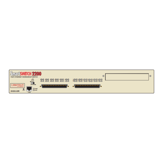
Figure The 2H253-25R SmartSwitch 2200... 1-1 Tabletop or Shelf Installation... 3-4 Attaching the Strain-Relief Bracket ... 3-5 Attaching the Rackmount Brackets ... 3-6 Installing the Device in a Rack ... 3-6 2H253-25R Rear View ... 3-7 Straight Cable Connection ... 3-9 LANVIEW LEDs ... - Page 16 Tables Table Contents of 2H253-25R Carton... 3-2 LANVIEW LEDs ... 4-2 Troubleshooting Checklist ... 4-5 COM Port Pin Assignments ... A-3 Page...
-
Page 17: About This Guide
SmartSwitch Series 2E253, 2H252, 2H253 and 2H258 Local Management User’s Guide. Depending on the firmware version used in the 2H253-25R, some features described in this document may not be supported. Refer to the Release Notes shipped with the 2H253-25R to determine which features are supported. -
Page 18: Related Documents
Interface Module (HSIM) or Very High Speed Interface Module (VHSIM) when one is installed. RELATED DOCUMENTS Cabletron Systems The following 2H253-25R: The following Cabletron Systems documents may help to set up and manage the 2H253-25R: • SmartSwitch Series 2E253, 2H252, 2H253 and 2H258 Local Management User’s Guide • Ethernet Technology Guide •... -
Page 19: Document Conventions
World Wide Web in Adobe Acrobat Portable Document Format (PDF) at the following site: http://www.cabletron.com/ All documentation for the Cabletron Systems SecureFast VLAN Manager software is NOTE contained on the VLAN Manager CD-ROM. -
Page 21: Important Notice
Cabletron Systems. Depending on the firmware version used in the 2H253-25R, some features described in this document may not be supported. Refer to the Release Notes shipped with the 2H253-25R to determine which features are supported. -
Page 22: Connectivity
VLAN according to priority and Ether type. Detailed information about VLANs is provided in the Cabletron Systems 802.1Q VLAN User’s Guide. The 2H253-25R may be used as a tabletop unit or can be installed in a standard 19-inch rack using the supplied rack mounting hardware. -
Page 23: Runtime Ip Address Discovery
1.1.3 Runtime IP Address Discovery This feature enables the 2H253-25R device to automatically accept an IP address from a Boot Strap Protocol (BootP) server on the network without requiring a user to enter an IP address through Local Management. -
Page 24: Remote Monitoring (Rmon)
Cabletron Systems SmartTrunk User’s Guide. 1.1.6 Remote Monitoring (RMON) The 2H253-25R supports all nine Ethernet RMON groups. The Statistics, Alarms, Events and History groups are enabled on all ports by default. Cabletron Systems RMON Actions is a vendor-specific extension of RMON and provides the ability to set an “Action”... -
Page 25: Rate Limiting
This is accomplished by the transmitting device pausing its transmission while the receiving device processes the frames already received. The 2H253-25R supports the following two types of flow control: • Frame based 802.3x •... -
Page 26: Garp Switch Operation
SNMP compliant Network Management Software. Local Management described in the SmartSwitch Series 2E253, 2H252, 2H253 and 2H258 Local Management User’s Guide provides the ability to manage the 2H253-25R, and optional HSIMs and VHSIMs that support Ethernet. For information about Local Management for optional non-Ethernet HSIMs or VHSIMs, refer to their respective user’s guide. -
Page 27: Optional Hsims And Vhsims
For information on how to extract and compile individual MIBs, contact Cabletron Systems. 1.1.17 Year 2000 Compliant The 2H253-25R has an internal clock that can maintain the current time and date beyond the year 1999. 1.1.18 LANVIEW Diagnostic LEDs LANVIEW diagnostic LEDs serve as an important troubleshooting aid by providing an easy way to observe the status of individual ports and overall network operations. -
Page 28: Getting Help
Getting Help GETTING HELP For additional support related to this device or document, contact Cabletron Systems using one of the following methods: World Wide Web http://www.cabletron.com/ Phone (603) 332-9400 Internet mail support@cabletron.com ftp://ftp.cabletron.com/ Login anonymous Password your email address To send comments or suggestions concerning this document, contact the Cabletron Systems Technical Writing Department via the following email address: TechWriting@cabletron.com... -
Page 29: Network Requirements 2.1 Smarttrunk
Web site: http://www.cabletron.com/ SmartTrunk To connect the 2H253-25R to a network so it can take advantage of the SmartTrunk feature, there are certain rules concerning port connections and configurations that must be followed for proper operation. Refer to the Cabletron Systems SmartTrunk User’s Guide for additional information. -
Page 30: 100Base-Tx Network
100BASE-TX Network 100BASE-TX NETWORK The two RJ21 connectors on the front panel of the 2H253-25R each provide 12 fixed ports (ports 1 through 24) that support Category 5 UTP cabling. The device at the other end of the twisted pair segment must meet IEEE 802.3u 100BASE-TX Fast Ethernet network requirements for the... -
Page 31: Installation
This chapter provides the instructions required to install the 2H253-25R. A Phillips screwdriver is required to install options into the device or install the device into a rack. Follow the order of the sections listed below to correctly install the device. -
Page 32: Contents Of 2H253-25R Carton
INSTALLING OPTIONS Install any optional equipment before proceeding to NOTE If the 2H253-25R is to be installed with an optional HSIM or VHSIM, refer to the user’s guide of that device for the installation instructions. INSTALLING THE DEVICE The 2H253-25R may be installed on a tabletop, shelf, or in a 19-inch rack. -
Page 33: Tabletop Or Shelf Installation
Maintain a 2-inch clearance from the left, right, and rear sides of the device to provide adequate ventilation. Installation For a tabletop or shelf installation, locate the 2H253-25R within seven feet of its power source and on an unrestricted free surface area as shown in connection instructions. -
Page 34: Tabletop Or Shelf Installation
Figure 3-1 Tabletop or Shelf Installation 3.3.2 Rackmount Installation To install the 2H253-25R in a 19-inch rack, Cabletron Systems includes a strain-relief bracket for cable management and an accessory kit containing the rackmount brackets, and mounting screws to attach the rackmount brackets and strain-relief bracket. -
Page 35: Attaching The Strain-Relief Bracket
5/16-inch screws included with the 2H253-25R. Use of longer screws may damage the CAUTION unit. Place the 2H253-25R upside down (as shown in the strain-relief bracket to the bottom of the 2H253-25R using the four 8-32 x 5/16-inch pan-head screws. Figure 3-2 Attaching the Strain-Relief Bracket Figure... -
Page 36: Attaching The Rackmount Brackets
Locate the four 6-32 x 1/4-inch flathead screws in the rackmount kit. Use these screws to attach the rackmount brackets to the bottom of the 2H253-25R as shown in Figure 3-3 Attaching the Rackmount Brackets... -
Page 37: Connecting Power
The POWER LED turns ON (green) and the CPU LED alternates between green and amber during boot up. It takes approximately one minute for the 2H253-25R to boot up. If the power-up sequence is interrupted on this device, or if optional hardware has been... -
Page 38: Connecting To The Network
This section provides the procedures for connecting unshielded twisted pair (UTP) segments from the network or other devices to the 2H253-25R. To make connections to an optional HSIM or VHSIM installed in the HSIM/VHSIM slot of the 2H253-25R, refer to the associated user’s guide for the HSIM or VHSIM. -
Page 39: Straight Cable Connection
2 H 2 5 3 -2 5 R LED MODE Switch Tighten the two screws on the RJ21 straight cable connector to secure it to the device. The cable pinouts for a 25-pair cable (RJ21) can be found in the Cabletron Systems NOTE Cabling Guide. Refer to Verify that a link exists on each twisted pair segment of the RJ21 connector by checking that the associated port RX LED is on (flashing amber, blinking green, or solid green). -
Page 40: Completing The Installation
Repeat steps 1 through 4 above, until all connections have been made. COMPLETING THE INSTALLATION After installing the 2H253-25R and any optional HSIM or VHSIM, and making the connections to the network, proceed as follows: Secure the cables by running the cables along the strain-relief bracket and tying them to the strain-relief bracket using cable ties. -
Page 41: Troubleshooting Checklist
• Troubleshooting Checklist • Using the RESET Button 4.1 USING LANVIEW The 2H253-25R uses Cabletron Systems’ built-in visual diagnostic and status monitoring system called LANVIEW. The LANVIEW LEDs status to aid in diagnosing network problems. FAST ETHERNET WORKGROUP SWITCH MODE... - Page 42 Using LANVIEW The LED MODE switch is located on the front panel of the 2H253-25R as shown in This switch enables the user to change the function of the port LEDs. When the LED MODE switch is moved to the left, the LEDs indicate the receive (RX) and transmit (TX) status of the respective fixed ports (ports 1 through 24).
- Page 43 Solid. Functional. Amber Booting. Blinks amber and green while booting. Green The following port RX and TX LED indications are only valid when the LED MODE switch is in the RX-TX position. No link. (Receive) Green Solid. Port enabled, link, no activity.
- Page 44 Spanning Tree. Flashing. Indicates collision rate. Solid. Diagnostic failure. The following port DPX and SPD LED indications are only valid when the LED MODE switch is in the DPX-SPD position. Amber Port is operating in standard mode (10 Mbps or 100 Mbps).
-
Page 45: Troubleshooting Checklist
4.2 TROUBLESHOOTING CHECKLIST If the 2H253-25R is not working properly, refer to causes, and recommended actions to resolve the problem. Problem Possible Cause All LEDs are Loss of power. OFF. Installed improperly. No Local Autobaud is enabled, but the Management baud rate has not yet been Password screen. - Page 46 Guide for instructions to enable/disable ports. 1. Verify that all network connections between the network management station and the 2H253-25R are valid and operating. 2. If the problem continues, contact Cabletron Systems for assistance. 1. Verify that Spanning Tree is enabled.
- Page 47 1. Reenter the lost parameters as necessary. Refer to the SmartSwitch Series 2E253, 2H252, 2H253, and 2H258 Local Management User’s Guide for the instructions to configure the device through Local Management. 2. If the problem continues, contact Cabletron Systems for assistance. Troubleshooting...
-
Page 48: Using The Reset Button
RESET 2H253-25R RESET Button To reset the 2H253-25R processor, press and release the RESET button. The 2H253-25R goes through a reset process for approximately 60 seconds. Additional downtime may result as the device reenters the network. It is not recommended to press the RESET button while the device is already in reset... -
Page 49: A.1 Device Specifications
This appendix provides operating specifications for the Cabletron Systems 2H253-25R. Cabletron Systems reserves the right to change these specifications at any time without notice. DEVICE SPECIFICATIONS Processors: Dynamic Random Access Memory (DRAM): FLASH Memory: Shared Memory: PHYSICAL PROPERTIES Dimensions: Approximate Weight (Unit): MTBF (Predicted): Specifications... -
Page 50: A.4 Environmental Requirements
Electrical Specifications ELECTRICAL SPECIFICATIONS Line Input Range, Volts (V): Input Current, Amperes (A): Frequency, Hertz (Hz): Input Power, Volt Amperes (VA:) ENVIRONMENTAL REQUIREMENTS Operating Temperature: Storage Temperature: Operating Relative Humidity: INPUT/OUTPUT PORTS Ports 1 through 24: Interface Slot: Specifications 100–125 Vac 2.3 A 50/60 Hz 250 VA... -
Page 51: A.7 Regulatory Compliance
COM PORT PINOUT ASSIGNMENTS The COM port is a serial communications port that supports Local Management or connection to a UPS. Table A-1 shows the COM port pin assignments. Signal Name Transmit Data (XMT) Data Carrier Detect (DCD) Data Set Ready (DSR) Receive Data (RCV) Signal Ground (GND) Data Terminal Ready (DTR) -
Page 53: B.1 Required Tools
Use the following tools to perform the procedures provided in this appendix: • Antistatic wrist strap • Phillips screwdriver Optional Installations and Mode Switch Bank Settings B.1) (Section B.2) (Section B.4) (Section B.5) Optional Installations and Mode Switch Bank Settings (Section B.3) -
Page 54: Removing The Chassis Cover
REMOVING THE CHASSIS COVER This section describes how to remove the 2H253-25R chassis cover. DO NOT REMOVE THE COVER FROM THE 2H253-25R WHILE POWER IS APPLIED TO THE UNIT. HAZARDOUS VOLTAGES ARE PRESENT AND COULD CAUSE PERSONAL INJURY AND/OR DAMAGE THE UNIT. - Page 55 Before performing step b, mark the cables connected to the 2H253-25R according to their associated port numbers. This is recommended for ease of reinstallation. Disconnect all network cables attached to the 2H253-25R. If the 2H253-25R is rack mounted, remove it from the rack and remove the rackmount brackets (refer to Chapter Use a Phillips screwdriver to remove the four screws attaching the cover to the chassis.
-
Page 56: B-1 Removing The Chassis Cover
Note: If the device was rack mounted, the four screws fastening the cover to the front panel are removed and installed along with the rackmount brackets. 2504-30 Figure B-1 Removing the Chassis Cover Optional Installations and Mode Switch Bank Settings... -
Page 57: B-2 Mode Switch Location
FRONT PANEL • Switch 6 – Forced BootP. After changing the position of switch 6, DO NOT reapply power to the chassis until there NOTE is a station on the network acting as a BootP server, which contains the downloadable firmware image file. -
Page 58: B.4 Simm Upgrade
Transfer Protocol (TFTP) server containing the 2H253-25R image file. When the position of Switch 6 is changed and the power is cycled to the 2H253-25R, the device requests the image file location from the BootP server and uses TFTP to download the image from the TFTP server. -
Page 59: B-3 Simm Slot Locations
TOP VIEW WITHOUT COVER Redundant Primary Power Power Supply Supply FRONT PANEL Figure B-3 SIMM Slot Locations Figure B-4 and proceed as follows: Figure Optional Installations and Mode Switch Bank Settings SIMM Upgrade 2504-84 B-4, insert the SIMM down... -
Page 60: B-4 Installing The Dram
Pivot the SIMM downward so the connector clips align with the two side notches of the SIMM and the connector clips lock the SIMM into place. Connector Connector Teeth Clip Side Notch Clip Alignment Notch SIMM Side Notch 2504-91 Figure B-4 Installing the DRAM Optional Installations and Mode Switch Bank Settings... -
Page 61: B-5 Hsim And Vhsim Connector Locations
Primary Power Supply Figure B-5 HSIM and VHSIM Connector Locations Installing Optional HSIM or VHSIM Interface Modules TOP VIEW WITHOUT COVER Redundant Power Supply FRONT PANEL Optional Installations and Mode Switch Bank Settings Optional HSIM or VHSIM Connectors 2504-31... -
Page 63: Index
Numerics 100BASE-T requirements 10BASE-T requirements 2H253-25R description of front panel 802.1p Port Priority introduction to Auto-Negotiation introduction to Broadcast Suppression introduction to Cable specifications 100BASE-TX network 10BASE-T network Chassis cover, removal of COM port pin assignments Connecting to the network... - Page 64 Index LANVIEW LEDs Local Management introduction to Management use of Memory upgrading Mode Switch setting Network connections Physical properties Port Redirect Function, introduction to Power connection Redirect functions port and VLAN, introduction to Regulatory Compliance Related manuals Remote Monitoring (RMON)
Need help?
Do you have a question about the 2H253-25R and is the answer not in the manual?
Questions and answers