Cabletron Systems 2200 Installation & User Manual
Cabletron systems installation user's guide smartswitch 2200
Hide thumbs
Also See for 2200:
- User manual (160 pages) ,
- Installation & user manual (64 pages) ,
- Instruction sheet (4 pages)
Table of Contents
Advertisement
Quick Links
Download this manual
See also:
User Manual
Advertisement
Table of Contents
Troubleshooting

Related Manuals for Cabletron Systems 2200


Summary of Contents for Cabletron Systems 2200
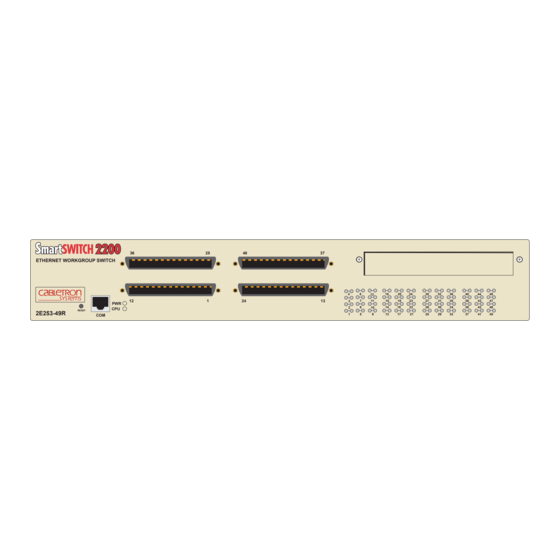
- Page 1 SmartSwitch 2200 Installation User’s Guide ETHERNET WORKGROUP SWITCH RESET 2E253-49R 9033216 2E253-49R...
- Page 3 NOTICE Cabletron Systems reserves the right to make changes in specifications and other information contained in this document without prior notice. The reader should in all cases consult Cabletron Systems to determine whether any such changes have been made. The hardware, firmware, or software described in this manual is subject to change without notice.
-
Page 4: Fcc Notice
FCC NOTICE This device complies with Part 15 of the FCC rules. Operation is subject to the following two conditions: (1) this device may not cause harmful interference, and (2) this device must accept any interference received, including interference that may cause undesired operation. -
Page 5: Program License Agreement
BEFORE OPENING OR UTILIZING THE ENCLOSED PRODUCT, CAREFULLY READ THIS LICENSE AGREEMENT. This document is an agreement (“Agreement”) between You, the end user, and Cabletron Systems, Inc. (“Cabletron”) that sets forth your rights and obligations with respect to the Cabletron software program (“Program”) in the package. - Page 6 If the Program is exported from the United States pursuant to the License Exception TSR under the U.S. Export Administration Regulations, in addition to the restriction on transfer set forth in Sections 1 or 2 of this Agreement, You agree not to (i) reexport or release the Program, the source code for the Program or technology to a national of a country in Country Groups D:1 or E:2 (Albania, Armenia, Azerbaijan, Belarus, Bulgaria, Cambodia, Cuba, Estonia, Georgia, Iraq, Kazakhstan, Kyrgyzstan, Laos, Latvia, Libya, Lithuania, Moldova, North Korea, the People’s Republic of China, Romania, Russia, Rwanda, Tajikistan, Turkmenistan, Ukraine, Uzbekistan, Vietnam, or such other countries as may be...
- Page 7 BEFORE OPENING OR UTILIZING THE ENCLOSED PRODUCT, CAREFULLY READ THIS LICENSE AGREEMENT. This document is an agreement (“Agreement”) between You, the end user, and Cabletron Systems Sales and Service, Inc. (“Cabletron”) that sets forth your rights and obligations with respect to the Cabletron software program (“Program”) in the package.
- Page 8 UNITED STATES GOVERNMENT RESTRICTED RIGHTS. The enclosed Product (i) was developed solely at private expense; (ii) contains “restricted computer software” submitted with restricted rights in accordance with section 52.227-19 (a) through (d) of the Commercial Computer Software-Restricted Rights Clause and its successors, and (iii) in all respects is proprietary data belonging to Cabletron and/or its suppliers.
- Page 9 BEFORE OPENING OR UTILIZING THE ENCLOSED PRODUCT, CAREFULLY READ THIS LICENSE AGREEMENT. This document is an agreement (“Agreement”) between You, the end user, and Cabletron Systems Limited (“Cabletron”) that sets forth your rights and obligations with respect to the Cabletron software program (“Program”) in the package.
- Page 10 If the Program is exported from the United States pursuant to the License Exception TSR under the U.S. Export Administration Regulations, in addition to the restriction on transfer set forth in Sections 1 or 2 of this Agreement, You agree not to (i) reexport or release the Program, the source code for the Program or technology to a national of a country in Country Groups D:1 or E:2 (Albania, Armenia, Azerbaijan, Belarus, Bulgaria, Cambodia, Cuba, Estonia, Georgia, Iraq, Kazakhstan, Kyrgyzstan, Laos, Latvia, Libya, Lithuania, Moldova, North Korea, the People’s Republic of China, Romania, Russia, Rwanda, Tajikistan, Turkmenistan, Ukraine, Uzbekistan, Vietnam, or such other countries as may be...
- Page 11 DECLARATION OF CONFORMITY Application of Council Directive(s): 89/336/EEC Manufacturer’s Name: Cabletron Systems, Inc. Manufacturer’s Address: European Representative Name: Mr. J. Solari European Representative Address: Conformance to Directive(s)/Product Standards: Equipment Type/Environment: Networking Equipment, for use in a Commercial We the undersigned, hereby declare, under our sole responsibility, that the equipment packaged with this notice conforms to the above directives.
-
Page 13: Table Of Contents
Remote Monitoring (RMON) ... 1-4 Broadcast Suppression... 1-4 Port/VLAN Redirect Functions ... 1-4 Traffic Rate Limiting ... 1-5 Flow Control... 1-5 GARP Switch Operation ... 1-6 802.1 Port Priority ... 1-6 Management ... 1-6 Switching Options ... 1-6 Optional HSIMs and VHSIMs... 1-7 Standards Compatibility ... - Page 14 Physical Properties ...A-1 Electrical Specifications ...A-2 Environmental Requirements...A-2 Input/Output Ports ...A-2 COM Port Pinout Assignments ...A-3 Regulatory Compliance...A-3 OPTIONAL INSTALLATIONS AND MODE SWITCH BANK SETTINGS Required Tools...B-1 Removing the Chassis Cover...B-2 Setting the Mode Switches...B-5 SIMM Upgrade ...B-6 B.4.1 B.4.2 Installing Optional HSIM or VHSIM Interface Modules ...B-9...
-
Page 15: Figures
Figure 2E253-49R SmartSwitch 2200 Device ... 1-1 Tabletop or Shelf Installation... 3-4 Attaching the Strain-Relief Bracket ... 3-5 Attaching the Rackmount Brackets ... 3-6 Installing the Device in a Rack ... 3-7 2E253-49R Rear View... 3-8 Straight Cable Connection ... 3-9 Connection Using the RJ21 Angle Adapter... - Page 16 Tables Table Contents of 2E253-49R Carton... 3-2 LANVIEW LEDs ... 4-2 Troubleshooting Checklist ... 4-5 COM Port Pin Assignments ...A-3 Page...
-
Page 17: About This Guide
This guide is organized as follows: Chapter 1, Introduction, provides an overview of the 2E253-49R and its features. Directions for obtaining additional information or help from Cabletron Systems are also included in this chapter. Chapter Network Requirements, explains the network requirements that must be met before installing the 2E253-49R. -
Page 18: Related Documents
Mode Switch, and shows the location of an optional High Speed Interface Module (HSIM) or Very High Speed Interface Module (VHSIM). RELATED DOCUMENTS The following Cabletron Systems documents may help to set up and manage the 2E253-49R: • SmartSwitch Series 2E253, 2H252, 2H253, and 2H258 Local Management User’s Guide •... -
Page 19: Document Conventions
World Wide Web in Adobe Acrobat Portable Document Format (PDF) at the following site: http://www.cabletron.com/ All documentation for the Cabletron Systems SecureFast VLAN Manager software is NOTE contained on the VLAN Manager CD-ROM. -
Page 21: Important Notice
This chapter introduces the 2E253-49R SmartSwitch 2200 device and provides information about how to obtain additional support from Cabletron Systems. Depending on the firmware version used in the 2E253-49R, some features described in this document may not be supported. Refer to the Release Notes shipped with the 2E253-49R to determine which features are supported. -
Page 22: Connectivity
Virtual Local Area Networks (VLANs) and control the flow of frames associated with each VLAN according to priority and Ether type. Detailed information about VLANs is provided in the Cabletron Systems SmartSwitch Series 2E253, 2H252, 2H253, and 2H258 Local Management User’s Guide. -
Page 23: Standard/Full Duplex Auto-Negotiation
1.1.3 Standard/Full Duplex Auto-Negotiation Ports 1 through 48 on the 2E253-49R have the ability to auto-negotiate the port mode of operation (standard [half duplex] or full duplex) between two devices according to the 802.3x standard. Full duplex mode is the default mode of operation for each port. During Auto-Negotiation, two devices automatically exchange information “telling”... -
Page 24: Remote Monitoring (Rmon)
History groups are enabled on all ports by default. Cabletron Systems RMON Actions is a vendor-specific extension of RMON and provides the ability to set an “Action” on any SNMP MIB variable. The Action can be triggered by any RMON Event and/or Alarm. -
Page 25: Traffic Rate Limiting
1.1.9 Traffic Rate Limiting The Rate Limiting feature enables the SmartSwitch device to have control over traffic rates on a per-port, per-priority basis. The network administrator can configure a rate limit (from 100 kbps to 1 Gbps) for a given port with an associated list of IEEE 802.1p priorities (which can include one, some, or all of the eight priority levels defined in 802.1p). -
Page 26: Garp Switch Operation
GARP attributes such as VLAN and multicast group membership. For more details on how GVRP and GMRP handle frames under GARP, and how to configure the switch ports to take advantage of this operation, refer to the Cabletron Systems SmartSwitch Series 2E253, 2H252, 2H253, and 2H258 Local Management User’s Guide. -
Page 27: Optional Hsims And Vhsims
RFC 1757 (RMON), RFC 1493 (Bridge MIB), RFC 1354 (FIB MIB), and RFC 1190 (Path MTU Discovery). A full suite of Cabletron Systems Enterprise MIBs provide a wide array of statistical information to enhance troubleshooting. For information on how to extract and compile individual MIBs, contact Cabletron Systems. -
Page 28: Getting Help
Getting Help GETTING HELP For additional support related to this device or document, contact Cabletron Systems using one of the following methods: World Wide Web http://www.cabletron.com/ Phone (603) 332-9400 Internet mail support@cabletron.com ftp://ftp.cabletron.com/ Login anonymous Password your email address To send comments or suggestions concerning this document, contact the Cabletron Systems Technical Writing Department via the following email address: TechWriting@cabletron.com... -
Page 29: Network Requirements 2.1 Smarttrunk
The network installation must meet the requirements to ensure satisfactory performance of this equipment. Failure to do so will produce poor network performance. The Cabletron Systems SmartTrunk User’s Guide and Cabling Guide referred to in the NOTE following sections can be found on the Cabletron Systems World Wide Web site: http://www.cabletron.com/... -
Page 31: Installation
Only qualified personnel should install the 2E253-49R. Read the Release Notes shipped with the device to check for any exceptions to the NOTE supported features and operation documented in this guide. This chapter provides the instructions required to install the 2E253-49R. A Phillips screwdriver is required to install options into the device or install the device into a rack. -
Page 32: Contents Of 2E253-49R Carton
Unpacking the Device UNPACKING THE DEVICE Unpack the device as follows: Open the box and remove the packing material protecting the 2E253-49R. Verify the contents of the carton as listed in Table 3-1 Contents of 2E253-49R Carton Item 2E253-49R Antistatic Wrist Strap Console Cable Kit RJ21 Angle Adapter Rackmount Kit... -
Page 33: Installing The Device
INSTALLING THE DEVICE The 2E253-49R may be installed on a tabletop, shelf, or in a 19-inch rack. a tabletop or shelf installation and To prevent possible personal injury and/or damage to the unit, do NOT connect power to the 2E253-49R until instructed to do so. 3.3.1 Tabletop or Shelf Installation The following two subsections provide guidelines for installation on a tabletop or shelf. -
Page 34: Tabletop Or Shelf Installation
Figure 3-1 Tabletop or Shelf Installation 3.3.2 Rackmount Installation To install the 2E253-49R in a 19-inch rack, Cabletron Systems includes a strain-relief bracket for cable management and an accessory kit containing the rackmount brackets, and mounting screws to attach the rackmount brackets and strain-relief bracket. -
Page 35: Attaching The Strain-Relief Bracket
2E253-49R using the four 8-32 x 5/16-inch pan-head screws. Strain-Relief Bracket Screws Figure 3-2 Attaching the Strain-Relief Bracket Figure Strain-Relief Bracket 2E253-49R RESET SWITCH WORKGROUP ETHERNET Installing the Device 3-2) on a clean flat surface. Then attach Installation 2600-03... -
Page 36: Attaching The Rackmount Brackets
With the mounting brackets attached, position the 2E253-49R between the vertical frame members of the 19-inch rack and fasten it securely with mounting screws as shown in Figure 3-4. Installation Rackmount Bracket CONSOLE TELCO SWITCH WORKGROUP Figure 3-3. Rackmount Bracket Screws 2E253-49R RESET ETHERNET... -
Page 37: Connecting Power
ETHERNET WORKGROUP SWITCH RESET 2E253-49R Screws Figure 3-4 Installing the Device in a Rack 3.3.3 Connecting Power The two power supplies in the 2E253-49R have automatic voltage sensing that allows NOTE connection to power sources ranging from 100–125 Vac, 2.5 A or 200–240 Vac, 1.25 A, 50/60 Hz. -
Page 38: Connecting To The Network
PWR LED is amber, there is no power redundancy. Check the power cord connections and the power source. If there are no problems with the power cord connections or power source and the PWR LED is still amber, contact Cabletron Systems. Refer to CONNECTING TO THE NETWORK This section provides the procedures for connecting unshielded twisted pair (UTP) segments from the network or other devices to the 2E253-49R. -
Page 39: Connection Using The Rj21 Angle Adapter
To connect an RJ21, proceed as follows: Ensure that the device connected to the other end of the segment is powered ON. If using an RJ21 straight connector, plug it into the appropriate RJ21 port as shown in Figure 3-6 or, if using the RJ21 right-angled adapter supplied with the device, insert it as shown Figure 3-7. -
Page 40: Completing The Installation
Tighten the two screws on the RJ21 straight cable connector or RJ21 angle adapter, as applicable, to secure it to the device. The cable pinouts for a 25-pair cable (RJ21) can be found in the Cabletron Systems NOTE Cabling Guide. Refer to... -
Page 41: Troubleshooting
Troubleshooting Checklist • Using the RESET Button 4.1 USING LANVIEW The 2E253-49R uses Cabletron Systems’ built-in visual diagnostic and status monitoring system called LANVIEW. The LANVIEW LEDs status to aid in diagnosing network problems. Viewing Receive and Transmit Activity Only one group of segments may be viewed at a time. - Page 42 Recommended Action 1. Ensure that the power cords are plugged in correctly and that there is power at the power source. 2. Contact Cabletron Systems for technical support. None. 1. Ensure that the power cords are plugged in correctly and that there is power at the power source.
- Page 43 Amber Flashing. Link, port enabled, activity. Solid. Diagnostic failure. Recommended Action Power up device. Contact Cabletron Systems for technical support. If the LED remains red for several minutes, contact Cabletron Systems for technical support. Contact Cabletron Systems for technical support.
- Page 44 Table 4-1 LANVIEW LEDs (Continued) Recommended Action 1. Ensure that the STA is enabled and that there is a valid link. 2. Contact Cabletron Systems for technical support. None. 1. Ensure that the port is not disabled. 2. Contact Cabletron Systems for technical support.
-
Page 45: Troubleshooting Checklist
Management User’s Guide for the Community Names Table setup. 2. If the Community Names have been forgotten, refer to instructions on how to set the mode switch to reset the Community Names to their default values. Troubleshooting Checklist for a checklist of problems, possible... -
Page 46: Reset Button
2E253-49R are valid and operating. 2. If the problem continues, contact Cabletron Systems for technical support. 1. Verify that Spanning Tree is enabled. Refer to SmartSwitch Series 2E253, 2H252, 2H253, and 2H258 Local Management User’s Guide for the... -
Page 47: Using The Reset Button
Pressing the RESET button resets the device, and all current switching being performed by the device is halted. A network downtime of up to two minutes will result from this CAUTION action. ETHERNET WORKGROUP SWITCH 2E253-49R RESET Button To reset the 2E253-49R processor, press and release the RESET button. The 2E253-49R goes through a reset process for approximately 60 seconds. -
Page 49: A.1 Device Specifications
This appendix provides operating specifications for the Cabletron Systems 2E253-49R. Cabletron Systems reserves the right to change these specifications at any time without notice. DEVICE SPECIFICATIONS Processors: Dynamic Random Access Memory (DRAM): FLASH Memory: Shared Memory: PHYSICAL PROPERTIES Dimensions: Approximate Weight (Unit):... -
Page 50: A.4 Environmental Requirements
Electrical Specifications ELECTRICAL SPECIFICATIONS Line Input Range, Volts (V) Input Current, Amperes (A) Frequency, Hertz (Hz) Input Power, Volt Amperes (VA) ENVIRONMENTAL REQUIREMENTS Operating Temperature: Storage Temperature: Operating Relative Humidity: INPUT/OUTPUT PORTS Ports 1 through 48 (four RJ 21 connectors): Interface Slot: Specifications 100–125 Vac... -
Page 51: A.7 Regulatory Compliance
COM PORT PINOUT ASSIGNMENTS The COM port is a serial communications port that supports Local Management or connection to a UPS. Table A-1 shows the COM port pin assignments. Signal Name Transmit Data (XMT) Data Carrier Detect (DCD) Data Set Ready (DSR) Receive Data (RCV) Signal Ground (GND) Data Terminal Ready (DTR) -
Page 53: B.1 Required Tools
Use the following tools to perform the procedures provided in this appendix: • Antistatic wrist strap • Phillips screwdriver Optional Installations and Mode Switch Bank Settings B.1) (Section B.2) (Section B.4) (Section Optional Installations and Mode Switch Bank Settings (Section B.3) B.5) -
Page 54: Removing The Chassis Cover
SIE VOR WARTUNGSARBEITEN DIE 2 NET ZANSCHLÜSSE VOM NETZ, UM ELEKTRISCHE SCHLÄGE ZU VERMEIDEN. ATTENTION: CET APPAREIL COMPORTE PLUS D’UN CORDON D’ALIMENTATION. RAFIN DE PREVENIR LES CHOCS ELECTRIQUES, DEGRANCHER LES DEUX CORDONS D’ALIMENTATION AVANT DE FAIRE LE DEPANNAGE. Optional Installations and Mode Switch Bank Settings... - Page 55 Remove the cover by sliding it back (1) until it clears the front of the chassis and then lifting it straight up (2) and off the chassis. To reinstall the chassis cover, perform the removal procedures in reverse. Optional Installations and Mode Switch Bank Settings Removing the Chassis Cover...
-
Page 56: B-1 Removing The Chassis Cover
Note: If the device was rack mounted, the four screws fastening the cover to the front panel are removed and installed along with the rackmount brackets. 2504-30 Figure B-1 Removing the Chassis Cover Optional Installations and Mode Switch Bank Settings... -
Page 57: B-2 Mode Switch Location
FRONT PANEL • Switch 6 – Forced BootP. After changing the position of switch 6, DO NOT reapply power to the chassis until there NOTE is a station on the network acting as a BootP server, which contains the downloadable firmware image file. -
Page 58: B.4 Simm Upgrade
Memory upgrade is available for the 2E253-49R to expand its DRAM to 32 MB. This section explains how to locate and add/replace a Single In-line Memory Module (SIMM). For information on the available SIMM upgrades, call Cabletron Systems. For details on getting help, refer to Section 1.2. -
Page 59: B-3 Dram Simm Connector Location
Locating SIMMs Figure B-3 shows the location of the DRAM SIMM connector. DRAM Figure B-3 DRAM SIMM connector Location TOP VIEW WITHOUT COVER Primary Redundant Power Power Supply Supply FRONT PANEL Optional Installations and Mode Switch Bank Settings SIMM Upgrade 26001-84... -
Page 60: Installing The Dram Simm
Pivot the SIMM downward so the connector clips align with the two side notches of the SIMM and the connector clips lock the SIMM into place. Connector Clip Side Notch Optional Installations and Mode Switch Bank Settings Figure B-4 and proceed as follows: Connector Teeth... -
Page 61: B-5 Hsim And Vhsim Connector Locations
TOP VIEW WITHOUT COVER Primary Power Supply Figure B-5 HSIM and VHSIM Connector Locations Installing Optional HSIM or VHSIM Interface Modules Redundant Power Supply FRONT PANEL Optional Installations and Mode Switch Bank Settings Optional HSIM or VHSIM Connectors 2600-31... -
Page 63: Index
Numerics 10BASE-T requirements 2E253-49R front panel 802.1p Port Priority introduction to Auto-Negotiation Broadcast Suppression introduction to Cable specifications 10BASE-T network Chassis cover, removal of COM port pin assignments Connecting to the network Connectivity introduction to Document conventions xvii Environmental requirements Flow control introduction to Getting help... - Page 64 Index Management use of Memory upgrading Mode Switch setting Network connections Physical properties Port redirect function introduction to Power connection Receive LEDs viewing of Redirect functions port and VLAN introduction to Regulatory Compliance Related manuals Remote Monitoring (RMON) introduction to...
Need help?
Do you have a question about the 2200 and is the answer not in the manual?
Questions and answers