Table of Contents
Advertisement
Quick Links
Advertisement
Table of Contents

Related Manuals for Eaton ESR5-VE3-42


Summary of Contents for Eaton ESR5-VE3-42
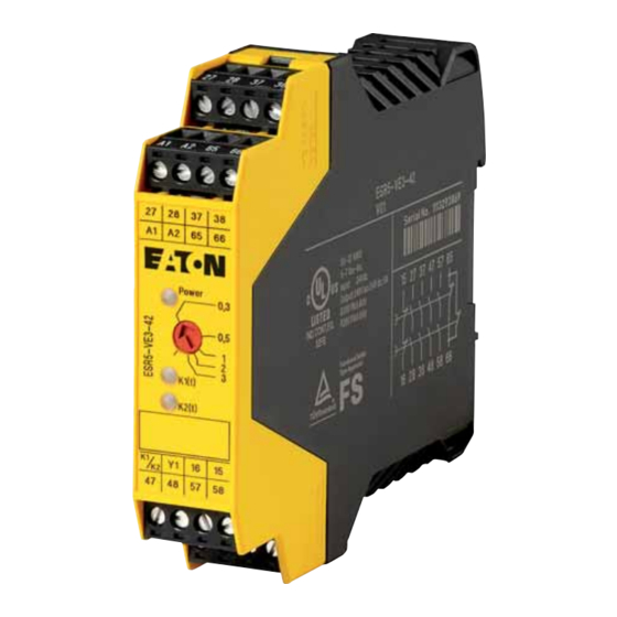
- Page 1 Manual 07/20 MN049003EN ESR5-VE3-42 Safety relay...
- Page 2 No part of this manual may be reproduced, stored in a retrieval system, or transmit- ted in any form or by any means, electronic, mechanical, photocopying, micro-film- ing, recording, or otherwise, without the prior written permission of Eaton Industries GmbH, Bonn, Germany.
- Page 3 Danger! Dangerous electrical voltage! Before commencing the installation • Disconnect the power supply of the device. • Wherever faults in the automation system may cause damage to persons or property, external measures must • Ensure that devices cannot be accidentally retriggered. be implemented to ensure a safe operating state in the •...
-
Page 5: Table Of Contents
Ordering data ................Safety notes................Description.................. Operating and indication elements.......... Connection Notes ................ Mounting and removing............Wiring..................Configuration................10 Startup ..................11 Protection against manipulation ..........12 Block Diagram ................13 Derating Curve ................14 Diagnostics ................. 15 ESR5-VE3-42 07/20 MN049003EN www.eaton.com... - Page 6 Connection Example..............16 Functional test / Proof-Test ............17 Technical data ................18 Glossary ..................21 ESR5-VE3-42 07/20 MN049003EN www.eaton.com...
-
Page 7: About This Manual
Use ESR5- VE3-42 for safe operation of a machine. An ESR5-VE3-42 may only be operated by a qualified electrician or a person who is familiar with electrotechnical installation, mounted and connected... -
Page 8: Abbreviations And Symbols
Warns of the possibility of hazardous situations that could result in serious injury or even death. DANGER Warns of hazardous situations that result in serious injury or death. 0.4.3 Tips → Indicates useful tips. 0.5 Ordering data ESR5-VE3-42 safety relay: Catalog No. 118706 ESR5-VE3-42 07/20 MN049003EN www.eaton.com... -
Page 9: Safety Notes
Risk of damage to equipment due to noise emissions When operating relay modules the operator must meet the requirements for noise emission for electrical and electronic equipment (EN 61000-6-4) on the contact side and, if required, take appropriate measures. ESR5-VE3-42 07/20 MN049003EN Eaton.com... -
Page 10: Description
2 Description 2 Description The safety relay ESR5-VE3-42 is used as a contact extension for safety relays for Emergency stop and safety door monitoring. The relay has four enabling current paths, one signalling current path and a feedback path. Depending on the set time, the contacts drop out with a delay of 0.3 s - 3 s,... -
Page 11: Operating And Indication Elements
Devices may only be mounted on/removed when the power is switched off. → In order to comply with UL approval, use copper cables that are designed for operating temperatures > 75°C. → For reliable and safe-to-touch contacts, strip the cable ends. ESR5-VE3-42 07/20 MN049003EN Eaton.com... -
Page 12: Mounting And Removing
4 Mounting and removing 4 Mounting and removing ▶ Mount the device on a 35 mm DIN rail according to EN 60715. ▶ To remove the device, use a screwdriver to release the snap-on foot. Figure 2: Mounting and removing ESR5-VE3-42 07/20 MN049003EN www.eaton.com... -
Page 13: Wiring
5 Wiring ▶ Connect the cables to the connection terminal blocks using a screwdriver. AWG 24-12 0.2 - 2.5 mm 7 mm (0.28“) 0.5 - 0.6 Nm (5 - 7 lb-in) Figure 3: Connecting the cables ESR5-VE3-42 07/20 MN049003EN Eaton.com... -
Page 14: Configuration
If the rotary switch is modified during operation, the safety relay switches to configuration mode and the LEDs flash. The safety relay is only ready for operation again once the supply voltage has been switched off and on again and configu- ration has been carried out. ESR5-VE3-42 07/20 MN049003EN www.eaton.com... -
Page 15: Startup
Switch off the voltage at input K1/K2. → The enable contacts open and the alarm contacts close after the set time has elapsed. → For additional connection examples, see → section 12, “Con- nection Example”, page 16. ESR5-VE3-42 07/20 MN049003EN Eaton.com... -
Page 16: Protection Against Manipulation
8 Protection against manipulation 8 Protection against manipulation Once the time has been set, the rotary switch can be protected against manipulation by covering with the label provided. Figure 4: Applying the label ESR5-VE3-42 07/20 MN049003EN www.eaton.com... -
Page 17: Block Diagram
9 Block Diagram 9 Block Diagram POWER Figure 5: Block diagram ESR5-VE3-42 07/20 MN049003EN Eaton.com... -
Page 18: Derating Curve
10 Derating Curve 10 Derating Curve [°C] Figure 6: Derating curve ESR5-VE3-42 07/20 MN049003EN www.eaton.com... -
Page 19: Diagnostics
Fault between contact points A1 and A2. Remove short circuit. ● ○ ○ Checkback contacts 15 and 16 faulty. Fault with ● ○ ● Enable contact of K1(t) faulty. Replace safety relays. internal cause ● ● ○ Enable contact of K2(t) faulty. ESR5-VE3-42 07/20 MN049003EN Eaton.com... -
Page 20: Connection Example
12 Connection Example 12 Connection Example Single-Channel connection with confirmation path 15-16 integrated in the basic device, suitable for up to safety category 3 ESR5-VE3-42 24 V DC Figure 7: Wiring via connection terminal blocks ESR5-VE3-42 07/20 MN049003EN www.eaton.com... -
Page 21: Functional Test / Proof-Test
If the device does not switch on again, the proof test failed. WARNING Loss of functional safety due to malfunction! If the proof test failed, the device will no longer function prop- erly. • Replace the device. ESR5-VE3-42 07/20 MN049003EN Eaton.com... -
Page 22: Technical Data
6 A (24 V DC) 5 A (230 V AC) Switching capacity (3600 cycles/h) 3 A (24 V (DC-13)) 3 A (230 V (AC-15)) Output fuse 10 A gL/gG NEOZED (N/O contact) 6 A gL/gG NEOZED (N/C contact) ESR5-VE3-42 07/20 MN049003EN www.eaton.com... - Page 23 - 2.5 mm Conductor cross section, stranded 0.2 mm - 2.5 mm Conductor cross section AWG/kcmil 24 - 12 Stripping length 7 mm Housing material Polyamide PA, not reinforced Tests / Approvals BG/TÜV geprüfte Sicherheit UL/CUL ESR5-VE3-42 07/20 MN049003EN Eaton.com...
- Page 24 300000 (at 5 A DC-13) Cycles 8760 per year Safety parameters for EN 62061 SIL CL 3 (in conjunction with suitable evaluating device) For SIL CL 3 applications the required demand rate for the safety function is once per month.. ESR5-VE3-42 07/20 MN049003EN www.eaton.com...
-
Page 25: Glossary
Classification of the ability of safety functions to meet a safety demand Safety integrity level SILCL SIL claim limit SRCF Safety-related control function SRECS Safety-related electrical control system (Safety-related electrical, electronic, and programmable electronic control system) Safety-related part SRP/CS Safety-related parts of control system ESR5-VE3-42 07/20 MN049003EN Eaton.com... - Page 26 15 Glossary ESR5-VE3-42 07/20 MN049003EN www.eaton.com...
- Page 27 Eaton’s electrical business is a global leader with expertise in power Eaton addresses worldwide distribution and circuit protection; backup power protection; control Eaton.com and automation; lighting and security; structural solutions and wiring devices;solutions for harsh and hazardous environments; and engi- neering services.Eaton develops innovations that not only provide...
Need help?
Do you have a question about the ESR5-VE3-42 and is the answer not in the manual?
Questions and answers