Table of Contents
Advertisement
Quick Links
Instructions
FLUID MANAGEMENT SYSTEMS
Used for bulk dispensing of petroleum and synthetic- based oils and antifreeze
to multiple service bays.
NOTE: These instructions are for software version 1.05
Important Safety Instructions.
Read all warnings and instructions in this manual.
Save these instructions.
t
308607J
EN
Advertisement
Table of Contents
Troubleshooting

Related Manuals for Graco Horizon Fluid Management Systems

Summary of Contents for Graco Horizon Fluid Management Systems
- Page 1 Instructions 308607J FLUID MANAGEMENT SYSTEMS Used for bulk dispensing of petroleum and synthetic- based oils and antifreeze to multiple service bays. NOTE: These instructions are for software version 1.05 Important Safety Instructions. Read all warnings and instructions in this manual. Save these instructions.
-
Page 2: Table Of Contents
Table of Contents Terms ........- - Diagnostics . -
Page 3: Terms
........Graco Standard Warranty .... -
Page 4: Symbols
D This equipment is for professional use only. D Read all instruction manuals, tags, and labels before operating the equipment. D Use the equipment only for its intended purpose. If you are uncertain about usage, call your Graco distributor. D Do not alter or modify this equipment. Use only genuine Graco parts and accessories. -
Page 5: Symboles
D Utilisez ce matériel seulement pour l’usage auquel il est destiné. En cas de doute, appelez votre distributeur Graco. D Ne pas altérer ou modifier ce matériel. N’utiliser que des pièces et accessoires Graco. D Vérifier le matériel quotidiennement. Réparer ou remplacer les pièces usagées ou endommagées immédiatement. -
Page 6: Pre-Installation Checklist
Pre-installation Checklist CAUTION Accurately and thoroughly document the Control Module port connections and dispense areas. If the Software Map does not exactly match the way the cables are connected, the system will not operate properly. Errors that could occur include: inability to turn on a fluid at a given dispense area; the wrong fluid or dispense point is acti- vated;... - Page 7 Pre-installation Checklist Pre-installation Steps Reference 7. Repeat the following steps for each control module: Floor Plan a. For each solenoid attached to the control module, assign one port num- ber, from 1 to 6. Record the port number and whether it is an air or fluid solenoid on the Floor Plan.
-
Page 8: Installation Checklist
Installation Checklist NOTE: D After completing the Pre-installation Checklist on page 6, use the following installation checklist to guide you through the steps of the system installation. D Refer also to Installation and Troubleshooting Tips, beginning on page 61, for information that will help you avoid installation problems and correct any problems that may occur. -
Page 9: System Startup
Installation Checklist System Startup Installation Steps Reference 13. Turn on the printer or computer. 14. Turn on the AC power to each control module. All the keypads should briefly Page 19 display a revision screen and then the HOME screen. The printer should print “WELCOME TO HORIZON...”... -
Page 10: Hardware Installation
Hardware Installation NOTE: CAUTION D Refer to the Detail drawing of the DIP switches in Fig. 1. It is important to follow the floor plan or note any D See page 73 for the location of the DIP switches in deviations as the software addresses will be setup the control module. -
Page 11: Change 110 Vac To 220 Vac
Hardware Installation 3. Set Control Module Addresses and Slave Control Modules are shipped with their address set to 0. Label the Boxes (continued) Address Switch 4. To Change from 110 VAC to 220 VAC Setting WARNING FIRE, EXPLOSION, AND ELECTRIC SHOCK HAZARD To reduce the risk of fire, explosion, and electric shock all wiring must be done by... - Page 12 Wire Connector Color black white black white transformer 110 VAC Connection 06652 Wire Connector Color black white black white wire nut transformer 220 VAC Connection 06897 Fig. 2 308607...
-
Page 13: Mount Control Module And Keypad Bracket
Hardware Installation 5. Mount the Control Module and Keypad Keypad Bracket Bracket See Fig. 4 for the mounting hole layout. Control Module D The control module(s) should be mounted near the hose reels. Control modules can be mounted on the wall or at ceiling level. -
Page 14: Cable Routing And Connection
Cable Routing and Connection 6. Connect the AC Electrical Power to the © Control Module WARNING FIRE, EXPLOSION, AND ELECTRIC SHOCK HAZARD £ To reduce the risk of fire, explosion, and electric shock: D All wiring must be done by a qualified electri- ground ©¢... -
Page 15: Route Solenoid And Meter Cables
Cable Routing and Connection 7. Route the Solenoid and Meter Cables Solenoid Connection to their Assigned Control Module P8 or P9 8. Connect the Solenoid and Meter ¢ Cables ¡ Connect the solenoid cables as shown in Fig. 6. The cables connect at the solenoid end with ©... -
Page 16: Connect Control Modules To Can
Cable Routing and Connection 9. Connect the Control Modules to the Control Module Connectors CAN (Controller Area Network) WARNING FIRE, EXPLOSION, AND ELECTRIC SHOCK HAZARD To reduce the risk of fire, explosion, and electric shock all wiring must be done by a qualified electrician. -
Page 17: Connect Keypad Cable
Cable Routing and Connection 10. Connect the Keypad Cable Old Style Printer: Set the DIP switches on the bottom of the printer as shown in Fig. 12. Route and connect the printer cable between the printer and the Master Route and connect the keypad cables (P/N 191393 (25 Control Module connectors. - Page 18 Cable Routing and Connection Connecting to Old Style Printer P/N 113774 Standard DIP Switch Settings for Old Style Printer 113774 Communication Settings D 9600 Baud Rate D No Parity D 1 Stop Bit D 8 Data Bits D No Software Handshaking ¡...
-
Page 19: System Setup - - Startup
This screen is displayed for four seconds after the HORIZON system is turned on, then the Mode Selection screen REV X.XX (or Home screen) appears. GRACO INC COPYRIGHT XXXX Mode Selection (HOME) NOTE: The SETUP option can only be modified on the administrator keypad. -
Page 20: Types Of Setup
System Setup - - Startup Instructions Screens Types of Setup SETUP Screens 1. SETUP screen appears. _ _ _ _ _ _ _ _ _ _" SETUP A_ _ _ _ _ _ _ _ _ _ 2. Cursor is on ENABLE/DISABLE CAN. ENABLE/DISABLE CAN 3. - Page 21 System Setup - - Enable/Disable CAN Instructions 5. The controller will return to the SETUP OPTIONS screen to allow another option to be selected and modified until HOME is pressed. Enable/Disable CAN Option Screens NOTE: See page 3 for CAN definition. _ _ _ _ _ _ _ _ _ _"...
-
Page 22: Enable/Disable Can Option
System Setup - - Modify or New Instructions Screens Modify Setup Options The options that can be defined in MODIFY SETUP include: D Time and date* D Assign connections 1. With the cursor at MODIFY SETUP, press ENTER D Operator pass- D Meter calibration on the keypad. -
Page 23: Clear Setup Options
System Setup - - Clear Setup Instructions Screens Clear Setup Options _ _ _ _ _ _ _ _ _ _" SETUP A_ _ _ _ _ _ _ _ _ _ MODIFY SETUP CAUTION " NEW SETUP CLEAR SETUP Clearing the OPERATOR PASSWORDS or ALL MEMORY will delete all passwords, including the CLEAR OPTIONS Screen... -
Page 24: Print Setup Options
System Setup - - Print Setup Instructions Screens Print Setup Options _ _ _ _ _ _ _ _ _ _" SETUP A_ _ _ _ _ _ _ _ _ _ NOTE: NEW SETUP " D Only the information for the control module the CLEAR SETUP keypad is connected to is printed. -
Page 25: Update Tables Options
System Setup - - Update Tables Instructions Screens Update Tables Options _ _ _ _ _ _ _ _ _ _" SETUP A_ _ _ _ _ _ _ _ _ _ CAUTION CLEAR SETUP " PRINT SETUP UPDATE TABLES Do not update tables while there are active or waiting jobs in the system. -
Page 26: Diagnostics
System Setup - - Diagnostics Instructions Screens Diagnostics _ _ _ _ _ _ _ _ _ _" SETUP A_ _ _ _ _ _ _ _ _ _ NOTE: PRINT SETUP " D The diagnostic information that appears on the UPDATE TABLES keypad screen refers to the control module the DIAGNOSTICS... -
Page 27: Meters Screens
System Setup - - Diagnostics Instructions Screens METERS Screens Diagnostics (continued) _ _ _ _ _ _ _ _ _ _" METERS A_ _ _ _ _ _ _ _ _ _ 8. The METERS screen appears with the cursor at MONITOR METERS the MONITOR METERS option. -
Page 28: Clear Printer Buffer Screen
System Setup - - Diagnostics Instructions Screens Diagnostics (continued) CLEAR PRINTER BUFFER Screen _ _ _ _ _ _ _ _" DIAGNOSTICS A_ _ _ _ _ _ _ _ 12. Entering CLEAR PRINTER BUF. will clear the KEYPAD printer buffer. Only use this option with printer "... -
Page 29: Time And Date
System Setup - - Time and Date Instructions Screens Set Time and Date NOTE: Only the Master Control Module can access the _ _ _ _ _ _ _ _" TIME & DATE A_ _ _ _ _ _ _ _ TIME AND DATE screen. - Page 30 System Setup - - Save Setup Instructions Screens Save Setup CAUTION SAVE SETUP: " NO " # WARNING: SAVE WILL CANCEL Do not save any setup information while there are ACTIVE/WAITING JOBS active or waiting jobs in the system. Active or waiting jobs will be canceled when you save setup.
-
Page 31: Important
System Setup - - Important! In order for the system to operate properly, the follow- D Complete the setup tables in the order they appear ing guidelines must be followed when entering the as information in consecutive screens is dependant following setup information: on information entered in previous screens. -
Page 32: Fluids
System Setup - - Fluids Instructions Screens Enter Fluid Data 1. Cursor is in the fluid number (FL01) field. FLO1 NAME: UNITS: QUARTS 2. The fluid number will automatically increment up # " ORDER: 01 by 1 as you add fluids or you can type the number EXIT DELETE identification of the fluid. -
Page 33: Dispense Areas
System Setup - - Dispense Areas Instructions Screens Define Dispense Areas 1. Cursor is in the dispense area number (DA01) DAO1 NAME: field. 2. The dispense area number will automatically increment up by 1 as you add areas or you can EXIT DELETE type the number identification of the area. -
Page 34: Connection Assignments
System Setup - - Connection Assignments Instructions Screens Assign Connections ASSGN CONN: DA01 FL01 1. The dispense area and fluid number appear in the AIR SOL: CM 01 PORT0 first row. FLD SOL: CM 01 PORT0 MTR#: 000 MORE EXIT The combined designation of the dispense area and fluid number is called the dispense point. -
Page 35: Meter Calibration
System Setup - - Meter Calibration Instructions Screens Set Meter Calibration 1. Cursor is in the METER NUMBER field. METER NUMBER: 001 CM# 01 PORT# 07 2. The meter number will display according to the 0001 PULSES PER QT order they were entered while assigning connec- MORE EXIT tions (page 34). -
Page 36: Inventory
System Setup - - Inventory Instructions Screens Set Inventory Levels If inventory tracking is disabled (default setting): INVENTORY TRACKING: D Can initiate any new jobs with preset or free flow. " DISABLE D Tank levels under INVNT menu will not count down. "# ARROWS TO CHANGE D Resettable/non-resettable totals will count up. -
Page 37: Comm. On
System Setup - - Inventory Instructions Save the Setup Follow the Save Setup procedure on page 30. To Disable Inventory Tracking: Screens 1. Cursor is in the ENABLE/DISABLE field. INVENTORY TRACKING: " DISABLE 2. Press the # or " key to scroll to DISABLE and "# ARROWS TO CHANGE press ENTER to confirm the setting and go to the ENTER KEY TO COMMIT... -
Page 38: Run Options
System Setup - - Run Options Instructions Screens Set Run Options RUN OPTIONS: PASSWORD? 1. Cursor is on YES in the PASSWORD? field in the JOB NUMBER? RUN OPTIONS screen. VEHICLE ID? 2. If it is desired to require the operator to enter a password, press ENTER with the cursor on YES. -
Page 39: System Time-Outs
System Setup - - System Time-outs Instructions 2. Type the number of minutes you want to elapse before the time-out will occur. Set System Time-outs 3. Press ENTER to confirm the setting and go to the Unused Keypad Time-out Dispense Time-out screen. If enabled, the keypad time-out helps avoid having an unauthorized person use an unattended keypad. -
Page 40: Printer And Computer Output
Printer and Computer Output Printer Output Format as Viewed on a Computer Screen Job Report Inventory Report 308607... - Page 41 Computer [Host] Output Format NOTE: The Master Output should be set to COM- Graco does not offer the software to create such PUTER. See page 37. Set up the computer to receive reports. The following screens provide you with the Horizon data as instructed on page 43.
- Page 42 Inventory Report Checksum (computer can use to validate transmission) Units for Inventory (gallons or liters) Amount currently in tank Fluid number I indicates an inventory report 308607...
-
Page 43: Computer: Receiving Horizon Data
Computer: Receiving Horizon Data Windows 3.1 4. Set as shown below (Baud Rate--9600, Data Bits--8, Stop Bits--1, Parity--None, Flow Control-- None, Connector--COM1), then select OK. The following instructions are for use with computers running Windows 3.1. Terminal Program Setup Follow these steps to provide the terminal program with the settings needed to receive Horizon data. -
Page 44: Windows 95 Setup
Computer: Receiving Horizon Data Windows 3.1 Windows 95 The following instructions are for use with computers Saving Horizon Job Records to running Windows 95. the Computer Terminal Program Setup Follow these steps to save the Horizon job records to Follow these steps to provide the terminal program the computer disk. - Page 45 Computer: Receiving Horizon Data 3. Enter a Name, select an Icon, and select OK. 4. A screen for the HyperTerminal you just created will appear. It will take you through each setup screen. 5. Pull down the menu for Connect using and select Direct to Com 1.
- Page 46 6. Set the COM1 Properties as shown below (Baud 7. Pull down the terminal File menu and select Save Rate--9600, Data Bits--8, Parity--None, Stop Bits--1, Flow Control--None), then select OK. 8. Type in the desired File Name (example: HORIZON.TRM). 9. Make sure the Save Files of Type is set to Termi- nal Files (*.TRM).
- Page 47 Computer: Receiving Horizon Data Windows 95 2. Make sure the Save Files of Type is set to Text Files (*.TXT). Saving Horizon Job Records to the Computer 3. Select the desired Drive and Directory where you want the Horizon data to be saved. Follow these steps to save the Horizon job records to the computer disk.
-
Page 48: Run Mode
This screen is displayed for four seconds after the REV X.XX system is turned on, then the Mode Selection screen GRACO INC (or HOME screen) appears. If the system was turned COPYRIGHT XXXX on previously, you will not see this startup screen. -
Page 49: New Job
Run Mode - - New Job Follow this procedure to start a fluid dispense job. Instructions Screens 1. Select New Job RUN NEW JOB Screens With the cursor at NEW JOB on the RUN screen, _ _ _ _ _ _ _ _ _ _" RUN A_ _ _ _ _ _ _ _ _ _ press ENTER on the keypad. -
Page 50: Dispense Request
Run Mode - - New Job Instructions Screens 3. Dispense Request DISPENSE REQUEST Screens NOTE: SEL FL:01 PENNZ10W30 SEL DA:01 BAY1 D Only valid dispense areas for the selected fluid are accepted as an entry. D If an invalid fluid or dispense area number was entered, a RUN ERROR screen will appear. -
Page 51: Preset Dispense
Run Mode - - New Job Instructions Screens 4. Preset Dispense PRESET DISPENSE Screen NOTE: SEL FL:02 PENNZ5W20 SEL DA:03 BAY3 D The unit of measurement (in this example, QT or PRESET AMOUNT?: YES quart) is entered during the System Setup. There are four units of measurement available: quarts, liters, gallons, and pints. -
Page 52: Dispense
Run Mode - - New Job Instructions Screens 7. Dispense ENTRY ACCEPTED Screen ENTRY ACCEPTED a.. After the dispense is confirmed, if the system STATUS: does not detect any problems, it will turn on the correct fluid and/or air solenoids, enable Processing... - Page 53 Run Mode - - New Job Instructions Screens 7. Dispense (continued) RUN Screen d.. Dispense the fluid. _ _ _ _ _ _ _ _ _ _" RUN A_ _ _ _ _ _ _ _ _ _ If the dispense was “preset”, the job will end NEW JOB by either reaching the preset amount or by tim- VIEW CURRENT JOBS...
-
Page 54: View Current Jobs
Run Mode - - View Current Jobs Follow this procedure to check the status of dispense jobs. Instructions Screens 1. Select View Current Jobs RUN Screen _ _ _ _ _ _ _ _ _ _" RUN A_ _ _ _ _ _ _ _ _ _ a.. -
Page 55: Report Jobs
Run Mode - - Report Jobs Follow this procedure to retrieve reports on previously completed jobs. This run option is only available on the Master Control Module. Instructions Screens 1. Select Report Jobs RUN Screen NOTE: _ _ _ _ _ _ _ _ _ _" RUN A_ _ _ _ _ _ _ _ _ _ D REPORT JOBS can be initiated when jobs are NEW JOB running, however, if a job completes and sends the... -
Page 56: Inventory Mode
This screen is displayed for four seconds after the REV X.XX system is turned on, then the Mode Selection screen GRACO INC (or HOME screen) appears. If the system was turned COPYRIGHT XXXX on previously, you will not see this startup screen. -
Page 57: Tank Levels
Inventory Mode - - Tank Levels Follow this procedure to check and add to the levels of your fluid tanks. Instructions Screens 1. Select Tank Levels INVENTORY Screen With the cursor at TANK LEVELS on the INVEN- _ _ _ _ _ _ _ _" INVENTORY A_ _ _ _ _ _ _ _ TORY screen, press ENTER on the keypad. -
Page 58: History Totals
Inventory Mode - - History Totals Follow this procedure to view how much fluid has been used over a given period of time. Instructions Screens 1. Select History Totals INVENTORY Screen With the cursor at HISTORY TOTALS on the _ _ _ _ _ _ _ _" INVENTORY A_ _ _ _ _ _ _ _ INVENTORY screen, press ENTER on the keypad. -
Page 59: Report Inventory
Inventory Mode - - Report Inventory Follow this procedure to print out the inventory levels of the fluid tanks. Instructions Screens 1. Select Report Inventory INVENTORY Screen _ _ _ _ _ _ _ _" INVENTORY A_ _ _ _ _ _ _ _ With the cursor at REPORT INVENTORY on the TANK LEVELS INVENTORY screen, press ENTER on the keypad. -
Page 60: Save Inventory
Inventory Mode - - Save Inventory Instructions Screens Save Inventory SAVE INVENTORY Screen CAUTION SAVE INVNT: " NO " # Inventory entries cannot be saved if there are any WARNING: active or waiting jobs in the system. The INVEN- JOBS MUST NOT BE TORY CANNOT BE SAVED screen will appear. -
Page 61: Installation And Troubleshooting Tips
Installation and Troubleshooting Tips General Precautions System Components and Installation Overview WARNING Control Module To reduce the risk of serious injury, read and follow Check each control module prior to mounting it on the the warnings on page 4. wall. D Never connect or disconnect system components 1. -
Page 62: Keypad
Installation and Troubleshooting Tips Keypad 3. Use the password 1111 to enter Setup. Move the cursor down to CLEAR SETUP and press ENTER. The keypad sends keystrokes to the control modules Press ENTER again to select ALL MEMORY. and receives characters back to write on the screen. It Answer YES to the prompt. -
Page 63: Installing And Troubleshooting A New Operating System Version
Installation and Troubleshooting Tips Installing and Troubleshooting a New b. Try SETUP " UPDATE TABLES " ALL TABLES to send the tables again (page 25), or Operating System Version you may have to CLEAR SETUP " ALL Installation MEMORY (page 23) to erase the memory of all control modules before sending the tables New versions of the Horizon operating system will again. -
Page 64: Troubleshooting System Components
Installation and Troubleshooting Tips Troubleshooting System Solenoids Components Problem: D Use DIP Switch #8 to turn on all the solenoids. See Controller Area Network (CAN) Fig. 1, page 10. NOTE: The switch only turns on the solenoids Problem: Network communication is not operating attached to that Control Module. -
Page 65: Meters
You will need to modify the " MONITOR METERS. See page 27. Graco printer cable or build a special cable as the pin NOTE: The meter numbers under DIAGNOSTICS assignments on most brands of printers are different. -
Page 66: Possible Problems And Solutions
Installation and Troubleshooting Tips Possible Problems and Solutions 1. The correct ready light comes on but 2. A different ready light comes on than no fluid flows. the one expected, and fluid flows at the dispense point indicated by the light. a. - Page 67 Installation and Troubleshooting Tips Possible Problems and Solutions 5. Jobs are compiling in the JOBS WAIT- A job that is in the active queue will time out after five minutes of inactivity. If a time shown in the ING queue or never clearing from the queue is more than five minutes old, the job is ACTIVE queue.
- Page 68 Troubleshooting Problem Cause Solution Keypad screen completely 1. No power to control module 1. Verify power is on blank 2. Keypad cable disconnected 2. Reconnect cable and cycle power to control module 3. Keypad malfunction 3. Replace keypad 4. Control module malfunction 4.
-
Page 69: Maintenance
Maintenance Shutdown Procedure 2. Disconnect the cable from the pulse meter, taking note of the wiring polarity. WARNING 3. Remove the screws (A). Lift off the electronic pulse module (1). See Fig. 14. ELECTRIC SHOCK HAZARD To reduce the risk of serious injury, 4. -
Page 70: To Clean The Solenoid Valve
Maintenance 4. Clean the parts and the seat in the body. Blow air WARNING into the body to clear the fluid passageways. ELECTRIC SHOCK HAZARD 5. Assemble the solenoid valve. To reduce the risk of serious injury, follow the Shutdown Procedure on 6. -
Page 71: Power Failure
If the problem seems to be with the control pins are in the holes. module, return it to your Graco Distributor or Installer for repair. 7. System Map Information is automatically updated and the transaction table is automatically cleared. -
Page 72: Horizon System Components
Horizon System Components Control Modules D It controls activity over the CAN (Controller Area Network), which is the network that interconnects Part No. 238624, Master Control Module the control modules in a larger system. D It provides the printer and/or computer interface. D It continuously tracks the time and date. - Page 73 Horizon System Components Control Module 06799 Control Module Component Identification NOTE: See page 78 for more information about sys- 6. Power Supply tem cables. Converts AC input power for use by control module 7. Power Supply Connector 1. Cable Port Holes Connects internal power supply to the electrical power source a.
-
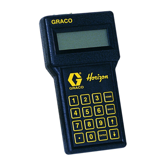
Page 74: Keypads
Horizon System Components Keypads Enhanced Keypad with Bar Code Reader The Enhanced Keypad provides all the functionality of Part No. 113551, Basic Keypad the Basic Keypad, with the added functionality of a bar code reader. Part No. 113552, Enhanced Keypad with Bar Code Reader Part No. -
Page 75: Keypad Wall-Mount Bracket
Horizon System Components Administrative Keypad Keypad Specifications: This keypad is needed to set up and make changes to D There can only be one Administrative Keypad in the the system parameters. It can only be connected to the system, and it can only be connected to the Master Master Control Module. -
Page 76: Fluid Solenoid Valves
Horizon System Components Fluid Solenoid Valves Air Solenoid Valves Part No. 215407, Air Solenoid Valve; Low Flow Part No. 218588, Fluid Solenoid Valve For low-air-flow requirement pump models, such as the 0 to 3 gpm (0--11.4 liter/min.), with Ready Light; See Eaglet and Fire-Ballr manual 307696 for more information Part No. -
Page 77: Pulse Meters
Horizon System Components Pulse Meters The electronic portion of part no. 238618, pulse meter for oils, ATF, and gear lube is available; see at left. The Part No. 238618, Pulse Meter Electronic Fluid Commander meter, part no. 236763, is For oil, ATF, or gear lube. Measures in pints, quarts, or not directly compatible with the Horizon system. -
Page 78: System Cables
Horizon System Components System Cables Keypad Cables (with connector) These cables connect keypads to control modules. For Keypad or Printer Connections (include connectors) They are available in 25 and 50 ft. (7.6 and 15.3 m) Part No. Length lengths, with 9-pin RS--232 connectors. Keypads can 191393 Keypad or 25 ft. - Page 79 Horizon System Components Solenoid Cable (bulk) Network Cable (bulk) Control modules are linked together with 2-conductor, These cables connect the air and fluid solenoids to the 22 AWG shielded cable, which is available in bulk control modules. They are 2-conductor, 18 AWG spools of 500 or 1000 ft.
-
Page 80: Pressure Relief Kit
Horizon System Components Pressure Relief Kit 40 Column Thermal Printer Part No. 207221, Pressure Relief Kit Part No. 113774, Thermal Printer 900 psi (6.2 MPa, 62 bar) Maximum Working Pressure Order power supply and paper separately. See below. For installation at the pump; see page 104. Relieves fluid line pressure when the pressure exceeds 900 psi Part No. -
Page 81: Appendix
Appendix 308607... -
Page 82: Horizon Software Features
Horizon Software Features The system is operated by responding to menus Fluid Supply Monitoring displayed on the keypad screen. The operator can The Inventory setup allows the user to monitor the select a fluid and its destination reel, enter the amount level of each tank on the system. -
Page 83: System Configuration
System Configuration Installation Considerations NOTE: See the Technical Data on page 107 for the system specifications. The Horizon system must be wired by an electrician and the installation must comply with local licensing 3. Place the fluid system components (pumps and and electrical codes. -
Page 84: System Configuration Examples
System Configuration System Configuration Examples Example 1 Parts List Qty. Component Example 1 Configuration D 3 fluids Master Control Module D All 3 fluids dispensed in each of 3 bays Slave Control Module D No simultaneous dispensing of the same fluid Keypad (could be Administrator Keypad for D One keypad in the office setup, or Basic Keypad for normal operation) - Page 85 System Configuration Example 2 Configuration Example 2 Parts List D 3 fluids Qty. Component D All 3 fluids dispensed in each of 3 bays Master Control Module D Simultaneous dispensing of all fluids to all bays D One keypad in the office, plus a keypad in each bay Slave Control Module D Printer in the office for output Keypads (could be 1 Administrator Keypad...
-
Page 86: Horizon Forms
Horizon Form #1 Graco, Inc. Horizon Horizon User Name, PIN Number and Access Level ACCESS LEVEL (check one) Name on System PIN Number Run & Run, Invt. User Name (4 characters max) (4 characters max) Inventory & Setup John Doe... - Page 87 Horizon Form #1 The following Horizon Form pages show examples of NOTE: Use the # or " keys to move the cursor to how to complete and use the forms to setup the sys- DELETE if you need to delete operator entrees. tem.
- Page 88 Horizon Form #2 Graco, Inc. Graco, Inc. Horizon Horizon Control Module & Fluid Names & Numbers l M d l & Fl id N & N CM Name in Software Map Control Module Location (10 Characters max) Master -- Near Office/Pumps...
- Page 89 Horizon Form #2 Use Form #2 as a guide for inputting the control mod- MASTER CONTROL MODULE Screen ule and fluid names. NAME CONTROL MODULES Name the Master Control Module CM#01 (MASTER CM) NAME: OFFICE _ _ _ _ NOTE: The first screen you access will be the Master EXIT Control Module screen CM#01.
- Page 90 Horizon Form #3 Graco, Inc. Graco, Inc. Horizon Horizon Dispense Area Names & Numbers & N Dispense Area Name in Software Map Dispense Area Location (10 Characters max) Service Bay #1 Service Bay #2 Service Bay #3 308607...
- Page 91 Horizon Form #3 Use Form #3 as a guide for inputting the names of the 8. If there are more dispense areas to add, press dispense areas. ENTER. 9. When all the dispense areas have been entered, You also define which fluids are available at each use the # or "...
- Page 92 Horizon Form #4 Graco, Inc. FLUIDS Name Name Name Name Name Name Name Name Name Name Connection Assignments 5/30 10/30 Record the Control Module # and port # for each solenoid (ports 1--6); number each me- ter consecutively (1,2,...) Example: CM1/3...
- Page 93 Horizon Form #4 Use Form #4 as a guide for inputting which solenoids 13. Press ENTER on the keypad. to turn on and which meter counts the pulses when 14. When the cursor is at MORE, press ENTER to dispensing specified fluids at specified dispense points. repeat the screen for each valid dispense point.
- Page 94 Horizon Form #5 Graco, Inc. Horizon Meter Calibration Chart No. Location Fluid CM # Port # Pulses Per Unit Bay #1 5/30 Oil Bay #1 10/30 Oil Bay #1 Bay #2 5/30 Oil Bay #2 10/30 Oil Bay #2 Bay #3...
- Page 95 Horizon Form #5 Use Form #5 as a guide for inputting the meter con- If using P/N 238618 Meter (for oil), set cal- nection address and to set the calibration (pulses per ibration at: unit) for each meter. 100 pulses per pint, 200 pulses per quart, 800 pulses per gallon, or 211 pulses per liter...
- Page 96 Horizon Form #6 Horizon Fluid Management Systems Warranty Registration and Checkout Form 1. Site Identification 2. Installer Identification Customer Name: Bob’s Service Garage Company Name: Pumps ’R Us Address: 123 Main Street Address: 9876 Elm Street City/State/Zip: Anytown, USA 12345...
-
Page 97: Blank Forms
Blank Forms 308607... - Page 98 Horizon Form #1 Graco, Inc. Horizon Horizon User Name, PIN Number and Access Level ACCESS LEVEL (check one) Name on System PIN Number Run & Run, Invt. User Name (4 characters max) (4 characters max) Inventory & Setup 308607...
- Page 99 Horizon Form #2 Graco, Inc. Graco, Inc. Horizon Horizon Control Module & Fluid Names & Numbers l M d l & Fl id N & N CM Name in Software Map Control Module Location (10 Characters max) Fluid Fluid Name in Software Map...
- Page 100 Horizon Form #3 Graco, Inc. Graco, Inc. Horizon Horizon Dispense Area Names & Numbers & N Dispense Area Name in Software Map Dispense Area Location (10 Characters max) 308607...
- Page 101 Horizon Form #4 Graco, Inc. FLUIDS Name Name Name Name Name Name Name Name Name Name Connection Assignments Record the Control Module # and port # for each solenoid (ports 1--6); number each me- ter consecutively (1,2,...) Example: CM1/3 Air Solenoid...
- Page 102 Horizon Form #5 Graco, Inc. Horizon Horizon Meter Calibration Chart No. Location Fluid CM # Port # Pulses Per Unit 308607...
- Page 103 Horizon Form #6 Horizon Fluid Management Systems Warranty Registration and Checkout Form 1. Site Identification 2. Installer Identification Customer Name: Company Name: Address: Address: City/State/Zip: City/State/Zip: Phone Number: Phone Number: Key Contact Name: Key Contact Name: 3. System Hardware Identification and Checkout...
-
Page 104: System Dynamics And Design Factors
System Dynamics And Design Factors Ability to Dispense Fluid During System There are some special factors that need to be consid- ered when designing a fluid distribution system that will Failure be controlled by a Horizon system. If this is a requirement, install a bypass near the fluid solenoid (B). - Page 105 System Dynamics And Design Factors Ability to Dispense Fluid During System In some cases, such as in mining applications, a design may be required that allows fluid to be dis- Failure (continued) pensed regardless of the state of operation of the Horizon system.
-
Page 106: Avoiding Pulsation When Simultaneous Dispensing Fluid
System Dynamics And Design Factors Avoiding Pulsation When Simultaneous WARNING Dispensing Fluid When simultaneously dispensing fluid, check valves (I) To reduce the risk of serious injury, the and pressure relief valves (J) need to be installed at pressure relief valves (J) are required to each pulse meter (G) to prevent false readings on one prevent the system from over-pressuriz- meter while other meter, solenoid (B), and valve com-... -
Page 107: Technical Data
Technical Data System Specifications 40 maximum Control Modules in a system (1 Master only, plus 39 Slave) 40 maximum Keypads in a system (1 keypad per Control Module; Administrators Keypad must be connected to the Master Control Module) 240 maximum Solenoids in a system (40 Control Modules, 6 ports each) 240 maximum Meters in a system (40 Control Modules, 6 ports each) -
Page 108: Graco Standard Warranty
With the exception of any special, extended, or limited warranty published by Graco, Graco will, for a period of twelve months from the date of sale, repair or replace any part of the equipment determined by Graco to be defective.
Need help?
Do you have a question about the Horizon Fluid Management Systems and is the answer not in the manual?
Questions and answers