
Subscribe to Our Youtube Channel
Related Manuals for PRONOVA SSM 6000


Summary of Contents for PRONOVA SSM 6000
- Page 1 User Manual SSM 6000 CONTINUOUS Date revised last: July 2007 Software Version 3.01 Version 800C-07.07.EN...
- Page 3 This manual contains information concerning installation, operation and maintenance/service of the analyzer system. Certain activities – such as replacing hardware components or changing internal settings – may only be carried out by qualified personnel. The manufacturer reserves the right to implement modifications at any time in order to adapt the user manual to the latest state of the art.
-
Page 5: Table Of Contents
Requirements for the plant of installation, power supply Measuring input and output conditions, calibration gases Scope of delivery, rating plate and test certificates Dimension drawing of the SSM 6000 system Installing the gas analyzer 3.5.1 Unpacking and assembling the gas analyzer 3.5.2... - Page 6 SSM 6000 CONTENTS CONT MENU AND FUNCTION OVERVIEW Measuring parameters 5.1.1 Measuring interval 5.1.2 Alarm values 5.1.3 Single measurement Calibration parameters 5.2.1 Gas types 5.2.2 Calibration gas concentrations 5.2.3 Start calibration Device options 5.3.1 Datalogger 5.3.2 Analog measured-value outputs 5.3.3 Sensor data 5.3.4...
- Page 7 SSM 6000 CONTENTS CONT MAINTENANCE, REPAIR, CUSTOMER SERVICE STATUS MESSAGES, TROUBLE-SHOOTING Limit-value alarms Trouble-shooting 10 WARRANTY CONDITIONS 11 APPENDIX 11.1 Technical specifications 11.2 Parts subject to wear and tear; spare parts 11.3 Declarations of conformity 11.4 Accessory connection cables 11.4.1 PORT 1 connection cable 11.4.2 PORT 2 connection cable...
-
Page 9: General Safety Information
SSM 6000 GENERAL SAFETY INFORMATION CONT General safety information The following safety information must always be observed during operation as well as during any maintenance and repair work on this device. Non-compliance with safety measures or any other information or warnings contained in this user manual constitutes a violation of safety standards underlying the design, manufacture and proper use of the device. -
Page 11: Introduction
The analyzer features ease of operation and a clear-cut display structure. In terms of time and frequency of use, the SSM 6000 family can draw on the largest experience of all biogas analyzers available on the market. The first analyzer developed in Europe specifically for continuous operation in biogas plants belongs to the SSM family and has been in use since 1998. -
Page 12: Importance Of The Measured Variables
Gas mixtures with critical concentration relationships between methane and oxygen are flammable. Although critical gas mixtures of this kind are very rare in biogas plants, the utmost must be done in order to avoid the risk of ignition. In the SSM 6000, a detonation protection unit separates the analyzer from the biogas plant. -
Page 13: Hardware Description
SSM 6000 HARDWARE DESCRIPTION CONT 2 HARDWARE DESCRIPTION Measuring characteristics The SSM 6000 Continuous analyzer was developed for the continuous measurement of CH , CO and for the discontinuous determination of H S and H concentrations in biogenic gases. The table below contains details concerning measuring ranges, etc. -
Page 14: Process Flow Chart And Measuring Process
SSM 6000 HARDWARE DESCRIPTION CONT 2.2.1 Process flow chart and measuring process Fig.: Process flow chart SSM6000Classic continuous Fig.: Process flow chart SSM6000LT continuous Detonation protection Needle valve (flow1) Needle valve (flow2) Measuring-gas cooler Flowmeter (flow1) Flowmeter (flow2) Hose pump... - Page 15 SSM 6000 HARDWARE DESCRIPTION CONT The measuring gas is initially drawn in through the safety device (1) of the selected measuring point (15) and cooled down to 5°C in the measuring-gas cooler (2). The hose pump (3) pumps the resultant condensate to the condensate discharge. The condensate must be collected and disposed of by the equipment user.
-
Page 16: Display And Control Panel
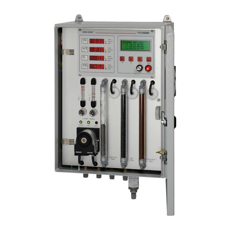
SSM 6000 HARDWARE DESCRIPTION CONT 2.2.2 Display and control panel The measured values are displayed for each gas type on the four-digit LED panels in the respective unit (Vol.% and ppm, respectively). In the case of devices with reduced functionality, the displays of gas types not included in the functionality remain inactive. -
Page 17: Measuring-Gas Filter
Measuring-gas filter Several filters are integrated into the gas path of the SSM 6000 in order to protect the sensors and other components of the system. The filters clean the biogas and the ambient air drawn in, thereby increasing both the service life of the sensors and the measuring precision of the system. -
Page 18: Measuring Gas Cooler (Option)
2.2.5 Measuring gas cooler (option) The SSM 6000 Classic analyzer version comes with a serial measuring-gas cooler. The SSM6000 LT is available with an optional measuring-gas cooler. Measuring-gas coolers are used in analyzer systems to process contaminated and humid measuring gases and to lower their dew point. -
Page 19: Gas Connections / Safety Features
The solenoid valves are controlled and the measuring points selected by the SSM 6000. A measuring process can be triggered manually via the digital inputs at port 1 or the (optional) Profibus interface. -
Page 20: Automatic Shut-Off Valve (Option)
1 must be interrupted during measuring breaks with admission pressures of more than 5 hPa, using suitable means, such as an automatic stop valve. The solenoid valve can be controlled via the "Measurement active" status output of the SSM 6000 on the underside of the analyzer (port 2). -
Page 21: Electrical Connections
The mains disconnector switch must be marked in a manner that clearly shows the equipment to be disconnected. Signals and interfaces The SSM 6000 analyzer comes with the following connections for communicating with peripheral equipment. Plug connector Description... -
Page 22: Hardware Installation
SSM 6000 HARDWARE INSTALLATION CONT 3 Hardware installation Requirements for the plant of installation, power supply All major system components are installed in a wall-mounted housing with IP20 protection. The device is hence designed for installation in closed, air-conditioned rooms. The device should be typically installed on a vertical wall in the central machinery room of the biogas plant as close as possible to the point of sampling. -
Page 23: Scope Of Delivery, Rating Plate And Test Certificates
20 m PVC hose 4x1mm (plus an additional 10m per measuring point with the measuring-point switch option) Replacement fuse for SSM 6000 (miniature fuse, 1A slow-blow, 4x20mm) Data cable for RS232 interface (length: 3m) User manual (German or English) CD-ROM with operating manually (pdf format) with gsd file for Profibus connection... -
Page 24: Dimension Drawing Of The Ssm 6000 System
HARDWARE INSTALLATION CONT Dimension drawing of the SSM 6000 system Fig.: Connection dimensions of the SSM 6000 During installation, free space of at least 15 cm must be left on the right hand side of the analyzer and at least 25 cm underneath the analyzer. -
Page 25: Installing The Gas Analyzer
SSM 6000 HARDWARE INSTALLATION CONT Installing the gas analyzer 3.5.1 Unpacking and assembling the gas analyzer Unpacking the gas Step Action analyzer Carefully remove the transport packaging of the analyzer, and store the analyzer in a clean place. Remove the rubber foam parts from the analyzer system. - Page 26 SSM 6000 HARDWARE INSTALLATION CONT Proceed in accordance with the applicable national safety regulations for the construction and operation of electrical systems as well as the safety information below! The connection between a protective earth connection and a protective earth conductor must be made before any...
- Page 27 SSM 6000 HARDWARE INSTALLATION CONT Fitting the power cable using QUICKON QUICKON components Union nut Crown Rubber seal Splice ring Contact support 1. Remove power cable Open screw connection. Pull the cable in order to separate the wires from the terminals.
- Page 28 SSM 6000 HARDWARE INSTALLATION CONT Port 1 - analog measured-value outputs / digital inputs One analog measured-value output is available at the plug connector, port 1. The maximum burden totals 550Ω. Furthermore, up to four digital inputs are available at port 1, depending on the analyzer version and its features.
-
Page 29: Connecting The Gas Pipes
SSM 6000 HARDWARE INSTALLATION CONT CAN interface (option) The CAN interface for the output of measured data via a CAN bus system is not yet supported by the software in its current version. Connector module at the analyzer: D-sub 9-pole, plug connector 3.5.3... - Page 30 SSM 6000 HARDWARE INSTALLATION CONT Measuring-gas input: The length of the biogas pipe should not exceed 50m. Stop valves should be installed at the sampling points of the biogas plant in order to prevent biogas from escaping when the measuring-gas hoses are disconnected. The measuring-gas pipe should, if possible, slope towards the sampling point, so that any condensate produced can flow back into the process.
-
Page 31: Using The Gas Analyzer
SSM 6000 USING THE ANALYZER CONT 4 Using the gas analyzer This section contains a brief description of how to use the analyzer in order to enable users to quickly start working with the device. For a detailed description of the individual functions and menu items, please refer to the following "Menu and function description"... -
Page 32: Starting A Measurement
Not every interval is permitted. The interval must be a divisor of 1440, i.e. the number of minutes of a day. If the value entered does not fulfill this requirement, the SSM 6000 automatically uses the nearest setting. With the setting selected above, H S is measured every 480 minutes and hence three times a day at 4:00 a.m., 12:00 noon, and 8:00 p.m, for... - Page 33 SSM 6000 USING THE ANALYZER CONT External start via the PROFIBUS interface S measuring process can also be started via the PROFIBUS interface. If the measuring-point switch option is implemented, the measuring-point to be analyzed is additionally selected. After the H S measuring cycle has been completed, the continuous measuring mode of the other components continues to be active until another measuring point is selected.
-
Page 34: Menu Structure
SSM 6000 USING THE ANALYZER CONT Menu structure In setup mode, analyzer settings and operating parameters can be made and changed by the SETUP MODE: user and/or service technician. _ MEASUREMENT _ CALIBRIATION The setup mode can be activated by means of the key-operated switch. -
Page 35: Menu And Function Overview
Not every interval is permitted. The interval must be a divisor of 1440, i.e. the number of minutes of a day. If the value entered does not fulfill this requirement, the SSM 6000 automatically uses the nearest setting. However, the measuring interval should not be set at a value of less than 120 minutes. - Page 36 SSM 6000 MENU AND FUNCTION OVERVIEW CONT 5.1.2 Alarm values menu selections for setting limit-value alarms can MEASURING GASES TEMPERATURES ALERT VALUES: be accessed via the menus. MEASURING PARAMETES / ALARM SETTINGS _MEAS. GASES _TEMPERATURES In the menu, separate concentration alarm thresholds can be set for each gas...
-
Page 37: Calibration Parameters
SSM 6000 MENU AND FUNCTION OVERVIEW CONT Calibration parameters Proceed with utmost care when using the "START GASCAL" function! Inappropriate or thoughtless calibration can completely misadjust the analyzer. Please proceed in strict conformity with the information in the "Calibration" section. -
Page 38: Device Options
SSM 6000 MENU AND FUNCTION OVERVIEW CONT Device options The DEVICE OPTIONS menu item contains the following options. SYSTEM OPTIONS: _ DATA OUTPUT _ OPERATION MODE _ DATE/TIME DATA OUTPUT: DATA LOGGER Digital output of measured values with time stamp... - Page 39 16.07.03 13:02;00,0;0001;20,8;00,0;23,8;1014;4; As a precondition for the transmission of data from the SSM 6000 to the PC, the terminal program must first be configured. This procedure is described here using the "HyperTerminal" program under MS Windows as an example. However, the properties of the serial interface can also be transferred to other terminal programs.
- Page 40 SSM 6000 MENU AND FUNCTION OVERVIEW CONT In the list box, select the serial interface of the Establish connection via: PC to which you wish to connect the , for example, COM1. SSM 6000 Thereafter, click to confirm. In this dialog, you must now configure the interface.
- Page 41 MENU AND FUNCTION OVERVIEW CONT Transmitting measured data As a precondition for transmitting measured values from the SSM 6000, the analyzer must be connected via the RS232 interface to the serial interface (COM1 or COM2) of the PC. Note: Use a suitable serial cable (1:1 connector layout) for this connection. The exact connector layout of the interface is shown in the terminal diagrams in the appendix.
- Page 42 SSM 6000 MENU AND FUNCTION OVERVIEW CONT Importing the measured data to MS Excel In order to import the transmitted measuring data, for example, to MS Excel, proceed as follows. Open the MS Excel spreadsheet program. Select the command in order to import the measured-value file (*.txt).
-
Page 43: Analog Measured-Value Outputs
SSM 6000 MENU AND FUNCTION OVERVIEW CONT 5.3.2 Analog measured-value outputs In the menu item, different settings can be made for the analog measured-value ANALOG OUTPUT ANALOG OUTPUT outputs. The parameterization level can be accessed in setup mode via Device options... -
Page 44: Sensor Data
SSM 6000 MENU AND FUNCTION OVERVIEW CONT 5.3.3 Sensor data The Sensor data menu serves the functional checking of the sensors and thereby supports remote SENSOR DATA: diagnosis by the manufacturer. _ ACTUAL _ HISTORY The current sensor signals and the signals of the last three measurements (HISTORY) can be displayed. -
Page 45: Operation Mode Auto/Manuell
DD:MM:YY format. _ DATE : 11:40:02 _ TIME : 07.11.04 Note that the clock of the SSM 6000 does not automatically switch to daylight saving time and winter time. Leap years are, however, considered. 800C-07.07.EN SSM 6000C User Manual... -
Page 46: Setting Into Operation
Switching the gas analyzer on In order to set the SSM 6000 into operation, proceed as follows: Connect voltage supply. Press the power button on the front panel in order to switch the analyzer on. -
Page 47: Setting The Measuring Interval
Not every interval is permitted. The interval must be a divisor of 1440, i.e. the number of minutes of a day. If the value entered does not fulfill this requirement, the SSM 6000 automatically uses the nearest setting. With the setting selected above, H S is measured every 480 minutes = three times a day at 4:00 a.m., 12:00 noon, and 8:00 p.m. -
Page 48: Checking The Interface Functions
SSM 6000 SETTING INTO OPERATION CONT Checking the interface functions The analyzer can simulate three analog output values in order to check the analog data output functionality and to adjust this to the higher-level plant control system, if necessary. This enables adjustment of external isolating switching amplifiers or arithmetic correction by the controller. -
Page 49: Starting Normal Measuring Operations
SSM 6000 SETTING INTO OPERATION CONT Starting normal measuring operations After all functions of the device are checked and if the test measurements indicate correct operation of the system, the analyzer can be switched to normal measuring mode. STAND-BY CONT. MEASUREMENT... -
Page 50: Calibration
In order to ensure correct measuring results within the specified tolerances, analyzers and systems must be calibrated at regular intervals. With the SSM 6000, the individual gas types are calibrated using certified calibration gases and/or calibration gas mixtures. Note that incorrect calibration leads to incorrect results during subsequent measurements! Before any service or maintenance intervention, the higher-level system (plant control system) must be notified of any such work in advance in order to avoid emergency shut-down of the motor in response to incorrect measuring values. -
Page 51: Recording The Actual Condition
CALIBRATION CONT The process of calibrating the SSM 6000 consists of the following steps: Rinsing the gas ducts and pipes with ambient air in order to record the sensor zero points Determining the sensor sensitivity values using biogas / calibration gas Rinsing the system using filtered ambient air. -
Page 52: Calibration Procedure
SSM 6000 CALIBRATION CONT Calibration procedure Calibration of the system can start after you have determined the ACTUAL condition and checked the sensor signals. The calibration menus are accessed after operation of the key switch via the selection level SETUP MODE CALIBRATION PARAMETERS. -
Page 53: Check Measurement
SSM 6000 CALIBRATION CONT When the zero points are accepted the request „CONNECT SPAN GAS!” is displayed. CALIBRATION Connect the span gas to the sample inlet for sample point 1 with a maximum pressure of 0.4bar CONNECT SPAN GAS! and confirm the request by pressing the <enter> key. -
Page 54: Calibrating The Oxygen Sensor
SSM 6000 CALIBRATION CONT Calibrating the oxygen sensor Besides the normal calibration routine, it is also possible to adjust the sensor sensitivity of the oxygen channel even without test gas because the sensor sensitivity is calibrated using ambient air and because the zero point of the oxygen sensor features long- time stability. -
Page 55: Maintenance, Repair, Customer Service
8 Maintenance, repair, customer service The SSM 6000 is a complex electronic measuring device and must hence be handled with care. The manufacturer is solely responsible for the original safety characteristics and features of the device. Any guarantee becomes void if the device is modified in any manner not performed or approved by the manufacturer. - Page 56 The analyzer should be checked and calibrated by the manufacturer or qualified technical personnel once a year. Defective devices must be taken out of operation and returned to the manufacturer after prior agreement. Pronova Analysentechnik GmbH & Co. KG Groninger Straße 25...
-
Page 57: Status Messages, Trouble-Shooting
SSM 6000 STATUS MESSAGES, TROUBLE-SHOOTING CONT 9 Status messages, trouble-shooting Limit-value alarms When the set limit value for one or more gas types is exceeded during measurement, the red status LED is lit up on the measured- value display for the respective gas type. The alarm messages at port 2 are also output as digital outputs and via the Profibus / CAN interface. -
Page 58: Warranty Conditions
The device is defective. If it is not possible to solve the problem, please contact the manufacturer. Pronova Analysentechnik GmbH & Co. KG Groninger Straße 25 13347 Berlin, Germany... -
Page 59: Appendix
SSM 6000 APPENDIX CONT 11 Appendix Appendix 800C-07.07.EN SSM 6000C User Manual... -
Page 61: Technical Specifications
SSM 6000 TECHNICAL SPECIFICATIONS CONT 11.1 Technical specifications Analyzer SSM6000 Other Gas type Measuring range Resolution Precision Measuring method Temperature and pressure Vol.%. ±2% FS Two-beam IR 0 ... 100 Vol.%. 0 ... 5.000 1 / 5 ±5% FS Electrochemical Dilution stages 1:200/40/10/0 (MP4) 0 ... - Page 62 SSM 6000 TECHNICAL SPECIFICATIONS CONT Electrical connection values Electrical connection, voltage suppy Power cable 3x0.75 mm² with earthed-contact plug Supply / incoming supply 230 VAC 50 Hz / 115VAC 60Hz option Power consumption 85 VA max. Fuses / overload protection...
-
Page 63: Parts Subject To Wear And Tear; Spare Parts
11.2 Parts subject to wear and tear; spare parts Article No. Description 800 - 0001 Filter set for SSM 6000 (3x 0007 / 1x 0003, 0005 and 0006 / 2x 0002 each) 800 - 0002 Filter mat for housing, 2-layer 800 - 0003... -
Page 64: Declarations Of Conformity
Declaration of conformity Manufacturer: Pronova Analysentechnik GmbH & Co. KG Groninger Straße 25 13347 Berlin Germany Product description: SSM 6000 / SSM 6000 LT / SSM 6000 C Determination of CH S, O , CO and H concentration Manufacturer No.:... - Page 65 SSM 6000 DECLARATIONS OF CONFORMITY CONT 800C-07.07.EN SSM 6000C User Manual...
- Page 66 SSM 6000 DECLARATIONS OF CONFORMITY CONT 800C-07.07.EN SSM 6000C User Manual...
- Page 67 SSM 6000 DECLARATIONS OF CONFORMITY CONT 800C-07.07.EN SSM 6000C User Manual...
-
Page 68: Accessory Connection Cables
SSM 6000 ACCESSORY CONNECTION CABLES CONT 11.4 Accessory connection cables 11.4.1 PORT 1 connection cable Ready-to-connect control cable, 10m or 20m long, for transmitting the signals to the general system controller. Other lengths on request. Color code (DIN 47100) Signals... -
Page 69: Port 2 Connection Cable
SSM 6000 ACCESSORY CONNECTION CABLES CONT 11.5 PORT 2 connection cable Ready-to-connect control cable, 10m or 20m long, for transmitting the signals to the general system controller. Other lengths on request. Color code (DIN 47100) Signals Connection cable specifications: white... -
Page 71: Connection Diagrams - Analyzer Versions A / B
SSM 6000 CONNECTION DIAGRAMS CONT 11.6 Connection diagrams – Analyzer versions A / B Connection diagrams 800C-07.07.EN SSM 6000C User Manual... - Page 89 SSM6000 Biogas Analyzer Description of the Profibus Interface...
- Page 91 Description PROFIBUS interface INTRODUCTION ELECTRICAL TRANSMISSION EQUIPMENT SSM6000 NTERFACE PROPERTIES OF THE US CABLE HIELDING ONNECTOR US TERMINATION ONNECTOR LAYOUT DATA TRANSMISSION ARAMETER DATA ONFIGURATION DATA YCLIC MODE CYCLIC MODE 3.4.1 EAD ACCESS 3.4.2 RITE ACCESS SSM6000 ATA MODULES OF THE ATA TYPES AND DATA FORMAT 3.6.1 FLOAT...
-
Page 93: Introduction
Description PROFIBUS interface Introduction This technical description deals with the Profibus DP (DP Decentralized Periphery) slave interface of the SSM6000. The correct description is as follows: Profibus-DP: Compliance to IEC 61784 Ed.1:2002 CPF 3/1 Electrical transmission equipment Interface properties of the SSM6000 The SSM6000 comes with a galvanically (optically) isolated Profibus interface according to IEC61784 Ed.1:2002 CPF3/2 (formerly EN50170). -
Page 94: Bus Termination
Description PROFIBUS interface Bus termination The PROFIBUS interface of the SSM6000 does not terminate the PROFIBUS at the device end. The SSM6000 does not set the open-circuit level of the bus at the device end. If this is required, the necessary measures must be implemented in the PROFIBUS connector. -
Page 95: Configuration Data
Description PROFIBUS interface In the parameter data telegram, the following pattern can appear for example 1: Param. DPV1-1 DPV1-2 DPV1-3 Module parameter P1..P7 Configuration data The configuration data is transmitted in the "special format". The following example refers to CH4: 42 , 83 , 00 , 01... -
Page 96: Cyclic Mode
Description PROFIBUS interface Cyclic mode The SSM6000 DP slave features a modular design. The data modules can be combined in any order for cyclic operation. It is not necessary to insert blank modules, and it is possible to select several modules at the same time. The only restriction is that the maximum number of inputs and outputs (as specified in the GSD file) may not be exceeded. -
Page 97: Data Modules Of The Ssm6000
Description PROFIBUS interface The same error message is generated if the "Measurement" data module was selected (parameterized) for cyclic data exchange. Otherwise the output value which is output in acyclic mode would be cyclically overwritten. Write access is possible via index 2 only. Write access attempts with another index trigger the "DPV1_ERRCL_ACC_INV_INDEX" error message (error code: 0B0 DS_Write telegram: 0x5F... - Page 98 Description PROFIBUS interface Analyzer status The analyzer status indicates whether the SSM6000 is in setup or measuring mode. The values transmitted have the following meanings: Value transmitted Mode 0x01 Setup mode 0x02 Measuring mode Alarms Table as an overview for the bit-coded alarms Alarm type CH4 over CH4 under...
-
Page 99: Data Types And Data Format
Description PROFIBUS interface Data types and data format The data transmitted via the Profibus is assigned to specific data types which, for their part, are stored in a specific data format. 3.6.1 FLOAT The "float" data type is transmitted as a 32-bit float value. 4 data bytes are required for this purpose. The bytes are stored as follows: Example: Float value: 1234.56... -
Page 100: Device Address And Id Number
Description PROFIBUS interface Device address and ID number Device address The device address is used to distinguish between the different devices within a Profibus network. Each device must have a distinct address and all devices must have different addresses. Address changes via the Profibus in the "Wait-Parameter" (WPRM) state are currently not supported by the SSM6000. -
Page 101: Gsd File
Description PROFIBUS interface GSD file ;* ================================================================================ * ;* Vendor: Novera Systemtechnik GmbH Groninger Str. 25 13347 Berlin Germany Tel.: +49-30-45029354 FAX.: +49-30-45029355 ;* ================================================================================ * ;* Function: SSM6K ;* Order Number : 43235000-gsd ;* -------------------------------------------------------------------------------- * ;* Author: R. Pandel Tel.: +49-30-45029354 FAX.: +49-30-45029355 ;* -------------------------------------------------------------------------------- *... - Page 102 Description PROFIBUS interface MaxTsdr_500=15 MaxTsdr_1.5M=20 MaxTsdr_3M=35 MaxTsdr_6M=50 MaxTsdr_12M=95 ;============================================================================== ;==== Slave specific values =================================================== ;============================================================================== Slave_Family = 3@PRONOVA@SSM6000 Implementation_Type "VPC3+" Bitmap_Device "ssm_AFFE" Freeze_Mode_supp=1 Sync_Mode_supp=1 Fail_Safe=1 Auto_Baud_supp=1 Set_Slave_Add_supp=0 Min_Slave_Intervall=20 Modular_Station=1 Max_Module=10 Modul_Offset=1 Max_Input_Len=51 Max_Output_Len=1 Max_Data_Len=52 Max_Diag_Data_Len=17 ;============================================================================== ;==== User-Prm-Data =========================================================== ;==============================================================================...
- Page 103 Description PROFIBUS interface Module="Temp (float) " 0x42,0x83,0x00,0x06 Ext_Module_Prm_Data_Len=5 Ext_User_Prm_Data_Const(0)=0x05,0x81,0x00,0x00,0x06 EndModule Module="Status (Byte) " 0x42,0x00,0x00,0x07 Ext_Module_Prm_Data_Len=5 Ext_User_Prm_Data_Const(0)=0x05,0x81,0x00,0x00,0x07 EndModule Module="Alarm (Byte) " 0x42,0x00,0x00,0x08 Ext_Module_Prm_Data_Len=5 Ext_User_Prm_Data_Const(0)=0x05,0x81,0x00,0x00,0x08 EndModule Module="Messen (Byte) " 0xC1,0x00,0x00,0x09 Ext_Module_Prm_Data_Len=5 Ext_User_Prm_Data_Const(0)=0x05,0x81,0x00,0x00,0x09 EndModule Module="AI (WORD) " 0x42,0x4A,0x00,0x0A Ext_Module_Prm_Data_Len=5 Ext_User_Prm_Data_Const(0)=0x05,0x81,0x00,0x00,0x0A EndModule ;============================================================================== ;==== DPV1 KEY WORDS ========================================================== ;============================================================================== DPV1_Slave C1_Read_Write_supp...
Need help?
Do you have a question about the SSM 6000 and is the answer not in the manual?
Questions and answers