
Related Manuals for BRP Rotax 915 i A Series


Summary of Contents for BRP Rotax 915 i A Series
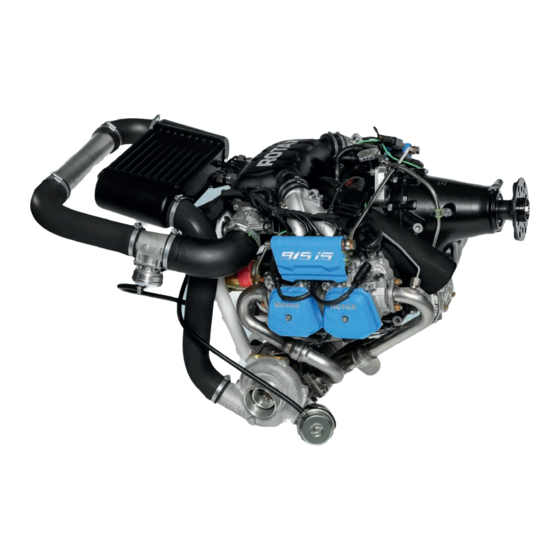
- Page 1 AIRCRAFT ENGINES Maintenance Manual (Line MAintenAnce) for rotAx® engine tYPe 915 i A SerieS ref. no.: MML-915 i A | part no.: 898863 picture: rotAx® 915 i A with options...
- Page 2 GmbH & CO KG, Austria, acc, BGBI 1984 no. 448, and shall not, without prior written permission of BRP-Rotax GmbH & Co KG, be disclosed in whole or in part to third parties. This legend shall be included on any reproduction of these data, in whole or in part. The Manual must remain with the engine/aircraft in case of sale.
- Page 3 BRP-Rotax MAINTENANCE MANUAL LINE Table of Content Chapter INTRO – GENERAL NOTE Chapter LEP – LIST OF EFFECTIVE PAGES Chapter TOA – TABLE OF AMENDMENTS Chapter 00–00–00 – GENERAL NOTE Chapter 04–00–00 – AIRWORTHINESS LIMITATIONS Chapter 05–00–00 – MAINTENANCE Chapter 05–10–00 –...
- Page 4 BRP-Rotax MAINTENANCE MANUAL LINE INTENTIONALLY LEFT BLANK Page 2 Effectivity: 915 i A Series June 01 2019...
- Page 5 ROTAX® Authorized Aircraft Engines Distributors or their independent Service Centers. BRP-Rotax wishes you much pleasure and satisfaction flying your aircraft powered by this ROTAX®-aircraft engine. The structure of the Manual follows whenever it is possible the structure of the ATA (Air Transport Association) standards.
- Page 6 BRP-Rotax MAINTENANCE MANUAL LINE INTENTIONALLY LEFT BLANK Page 2 Effectivity: 915 i A Series June 01 2019...
- Page 7 BRP-Rotax MAINTENANCE MANUAL LINE Chapter: LEP LIST OF EFFECTIVE PAGES Each new revision to the Maintenance Manual Line will have a new List of Effective Pages. page page chapter date chapter date Cover June 01 2019 page 05-00-00 June 01 2019...
- Page 8 BRP-Rotax MAINTENANCE MANUAL LINE page page chapter date chapter date June 01 2019 June 01 2019 June 01 2019 June 01 2019 June 01 2019 June 01 2019 June 01 2019 June 01 2019 05-50-00 June 01 2019 June 01 2019...
- Page 9 BRP-Rotax MAINTENANCE MANUAL LINE page page chapter date chapter date June 01 2019 June 01 2019 June 01 2019 June 01 2019 June 01 2019 June 01 2019 June 01 2019 June 01 2019 June 01 2019 June 01 2019...
- Page 10 BRP-Rotax MAINTENANCE MANUAL LINE INTENTIONALLY LEFT BLANK Page 4 Effectivity: 915 i A Series June 01 2019...
- Page 11 BRP-Rotax MAINTENANCE MANUAL LINE Chapter: TOA TABLE OF AMENDMENTS Approval* The technical content of this document is approved under the authority of DOA ref. EASA.21J.048. This document is part of the ICA for product [2019]. NOTE THE APPROVAL IS GIVEN TO ALL CHAPTERS EXCEPT THE AIRWORTHINESS LIMITATIONS SECTION 04-00-00 WHICH IS SUBJECT TO SPECIFIC APPROVAL OF THE EASA.
- Page 12 BRP-Rotax MAINTENANCE MANUAL LINE page Rev. chapter date of remark for date of date of signature change approval approval inclusion from authori- ties 05-00-00 4,6 - 10 June 01 2019 DOA* 05-10-00 June 01 2019 DOA* 05-20-00 2, 6, June 01 2019 DOA* 8–13...
- Page 13 BRP-Rotax MAINTENANCE MANUAL LINE Summary of amendments Summary of the relevant amendments in this context, but without requirement on completeness. page Rev. no. chapter date of change comment 00–00–00 June 01 2019 New: Wiring color code 00–00–00 June 01 2019 change of text 05–20–00...
- Page 14 BRP-Rotax MAINTENANCE MANUAL LINE INTENTIONALLY LEFT BLANK Page 4 Effectivity: 915 i A Series June 01 2019...
-
Page 15: Table Of Contents
BRP-Rotax MAINTENANCE MANUAL LINE Chapter: 00–00–00 GENERAL NOTE TOPICS IN THIS CHAPTER General..............................2 Abbreviations and terms .........................3 Wiring color codes ..........................7 Conversion table ...........................8 Safety notice ............................9 Safety information ..........................10 Instruction............................12 Maintenance Concept..........................13 Technical documentation........................14 Use for intended purpose ........................16 Effectivity: 915 i A Series 00–00–00... -
Page 16: General
BRP-Rotax MAINTENANCE MANUAL LINE GENERAL Purpose The purpose of this Manual is to provide aircraft manufacturers with technical require- ments (e.g. interface descriptions and limitations) that must be adhered to when installing this type of engine into an aircraft or certifying aircraft powered by this engine type. Fur- thermore it should allow independent ROTAX®... -
Page 17: Abbreviations And Terms
BRP-Rotax MAINTENANCE MANUAL LINE ABBREVIATIONS AND TERMS Abbreviations Description Reference to another section center of gravity The drop symbol indicates use of sealing agents, adhesives or lubri- cants (only in the Illustrated Parts Catalog). °C Degrees Celsius (Centigrade) °F Degrees Fahrenheit... - Page 18 BRP-Rotax MAINTENANCE MANUAL LINE DCDI Dual Capacitor Discharge Ignition direct current Design Organisation Approval Department of Transport EASA European Aviation Safety Agency Installation Manual Engine Control Unit Exhaust Gas Temperature INTRO Introduction Engine Management System EMS GND Engine system internal ground reference which is intended to be dis-...
- Page 19 Power supply PTFE Polytetrafluoroethylene (Teflon) Power Take Off Rev. Revision ROTAX® is a trademark of BRP-Rotax GmbH & Co KG Research Octane Number RON 424 ROTAX® Standard 424 s.v. still valid (only Illustrated Parts Catalog) Effectivity: 915 i A Series 00–00–00...
- Page 20 BRP-Rotax MAINTENANCE MANUAL LINE Serial Number Society of Automotive Engineers Single Engine Piston Service Bulletin Service Instruction SI-PAC Service Instruction Parts and Accessories SPST Single pole single throw Shield twisted pair Service Letter Surface Mounted Devices Time Between Overhaul Type certificate part no.
-
Page 21: Wiring Color Codes
BRP-Rotax MAINTENANCE MANUAL LINE WIRING COLOR CODES Figure 1.2 Effectivity: 915 i A Series 00–00–00 Rev. 1 Page 7 June 01 2019... -
Page 22: Conversion Table
BRP-Rotax MAINTENANCE MANUAL LINE CONVERSION TABLE Units of length: Units of power: 1 mm = 0.03937 in 1 kW = 1.341 hp 1 in = 25.4 mm 1 hp = 0.7457 kW 1 ft = 12 in 1 kW = 1.3596 PS = 0.3048 m... -
Page 23: Safety Notice
The information and descriptions of components and systems contained in this Manual are correct at the time of publication. BRP-Rotax maintains a policy of continuous im- provement of its products without imposing upon itself any obligation to retrofit products previously manufactured. -
Page 24: Safety Information
• Due to the varying designs, equipment and types of aircraft, BRP-Rotax grants no war- ranty on the suitability of its engines use on any particular aircraft. Further, BRP-Rotax... - Page 25 BRP-Rotax MAINTENANCE MANUAL LINE Engine operation • The engine must always be operated according to the content of the latest Operators Manual • To eliminate the risk of injury or damage, ensure any loose equipment or tools are prop- erly secured before starting the engine •...
-
Page 26: Instruction
GENUINE-ROTAX®-spare parts and/or accessories. Spare parts are available at ROTAX® Authorized Distributors and their independent Service Centers. Any warranty by BRP-Rotax will become void if spare parts and/ or accessories other than GENUINE-ROTAX®-spare parts and/or accessories are used (see latest War- ranty Conditions). -
Page 27: Maintenance Concept
BRP-Rotax MAINTENANCE MANUAL LINE See latest Operators Manual and Service Instruction SI-915 i-001 “Selec- tion of suitable operating fluids“, current issue. MAINTENANCE CONCEPT General note The maintenance functions detailed in this Manual are divided into two categories: • Maintenance I (Line Maintenance) •... -
Page 28: Technical Documentation
BRP-Rotax MAINTENANCE MANUAL LINE TECHNICAL DOCUMENTATION These documents form the instructions ensuring continued airworthiness of ROTAX® air- craft engines. The information contained herein is based on data and experience that are considered ap- plicable for authorized mechanics (iRMT, see Maintenance Manual Line) under normal conditions for engine removal and installation. - Page 29 BRP-Rotax MAINTENANCE MANUAL LINE Illustrations The illustrations in this Manual are merely sketches and show typical arrangements. They may not represent full detail or the exact shape of the parts but should outline the same or similar function. Therefore deriving dimensions or other details from illustrations is not permitted.
-
Page 30: Use For Intended Purpose
NOTE These engines are technically equivalent to certified engines and have been man- ufactured by BRP-Rotax using the same quality assurance system. Engine stoppage In using the engine the operator assumes all risk of use and acknowledges that he/she knows this engine is subject to sudden stoppage. - Page 31 BRP-Rotax MAINTENANCE MANUAL LINE Chapter: 04–00–00 AIRWORTHINESS LIMITATIONS TOPICS IN THIS CHAPTER Approval THE AIRWORTHINESS LIMITATIONS SECTION IS APPROVED BY THE EUROPEAN AVIATION SAFETY AGENCY (EASA) IN ACCORDANCE WITH PART 21A.31(a)(3) AND FAR 33.4. ANY CHANGE TO MANDATORY REPLACEMENT TIME, INSPECTION INTERVAL, AND RELATED PROCEDURES CONTAINED IN THIS AIRWORTHINESS LIMITATIONS SECTION MUST ALSO BE APPROVED.
- Page 32 BRP-Rotax MAINTENANCE MANUAL LINE INTENTIONALLY LEFT BLANK Page 2 Effectivity: 915 i A Series June 01 2019...
- Page 33 BRP-Rotax MAINTENANCE MANUAL LINE Chapter: 05–00–00 MAINTENANCE TOPICS IN THIS CHAPTER General note ............................2 Authorized personnel ..........................3 Procedure notes ............................4 Troubleshooting ............................6 Consumable Materials ..........................7 Acceptable methods, techniques and practice ..................11 Introduction The information given in the Maintenance Manual is based on data and experience which are considered to be applicable for a skilled aviation mechanic (iRMT) under normal working conditions.
-
Page 34: General Note
We particularly emphasize that parts and accessories not supplied as genuine BRP-Rotax accessories parts are not verified for suitability by BRP-Rotax and thus are not authorized for use. In- stallation and/or use of such products may possibly change or negatively influence the constructive characteristics of the engine. -
Page 35: Authorized Personnel
• ensure the requirements of the applicable regulatory authority regarding maintenance procedures are met. For more detailed information, maintenance organizations and individuals are encouraged to contact BRP-Rotax through its worldwide distribution network for information and guid- ance on any of the tasks outlined herein. Chapter 00-00-00 section Technical Documentation. -
Page 36: Procedure Notes
BRP-Rotax MAINTENANCE MANUAL LINE PROCEDURE NOTES General note m WARNING Non-compliance can result in serious injuries or death! When carrying out maintenance and service work, respect without fail all safety regulations. Ignition “OFF“ m WARNING Non-compliance can result in serious injuries or death! This precautionary measure serves to avoid any injuries in case of an unintentional start of the engine. - Page 37 BRP-Rotax MAINTENANCE MANUAL LINE Disassembly At disassembly of the engine, mark the components as necessary to avoid any mix-up. Take care of these marks, don’t ruin them. Tool ATTENTION In order to avoid mechanical damage, always loosen or tighten screws and nuts with specified tools.
-
Page 38: Troubleshooting
BRP-Rotax MAINTENANCE MANUAL LINE TROUBLESHOOTING General notes Possible problems are listed in the Operators Manual. At the same time, a brief description of the necessary remedial action is given. See Chapter 4 in the Operators Manual for engine type 915 i A Series. -
Page 39: Consumable Materials
CONSUMABLE MATERIALS General note ATTENTION Use only the specified or technically equivalent materials from BRP-Rotax for all maintenance work. When handling chemicals, comply with all the customary reg- ulations and specifications of the producer, including the expiry date and instruc- tions of use. - Page 40 BRP-Rotax MAINTENANCE MANUAL LINE part no. Description, Application Qty. 297711 PU-glue 310 ml For vibration damping (0.082 gal (US)) 297386 Locking paint 897186 SILICONE HEAT CONDUCTION COMPOUND 150 g (torque seal or whiteness paint), (0.33 lb) Application of the heat conduction compound will increase heat transfer resistance.
- Page 41 Additional materials ATTENTION Use only the specified or technically equivalent materials from BRP-Rotax for all maintenance work. When handling chemicals, comply with all the customary reg- ulations and specifications of the producer, including the expiry date and instruc- tions of use.
- Page 42 BRP-Rotax MAINTENANCE MANUAL LINE part no. Description, Application Qty. Compressed air blasting using a solid blasting agent This method is suitable for local and gradual very fine treatment of steel parts with rust film (propeller shaft). The MICRONORM abrasive contains no harmful substances, is approved by the competent authorities and guarantees optimum cleaning.
-
Page 43: Acceptable Methods, Techniques And Practice
BRP-Rotax MAINTENANCE MANUAL LINE ACCEPTABLE METHODS, TECHNIQUES AND PRACTICE General note All general inspection, maintenance and repair has to be carried out in accordance with Advisory Circular AC 43.13 from FAA. Advisory Circular This Manual "Advisory Circular" AC describes maintenance methods, techniques and practice. - Page 44 BRP-Rotax MAINTENANCE MANUAL LINE INTENTIONALLY LEFT BLANK Page 12 Effectivity: 915 i A Series June 01 2019...
-
Page 45: Introduction
BRP-Rotax MAINTENANCE MANUAL LINE Chapter: 05–10–00 TIME LIMITS TOPICS IN THIS CHAPTER Definition of terms ...........................2 Operating hours ............................2 Terminology ............................2 Time limit ..............................3 Life cycle ..............................3 General overhaul (TBO).........................3 Purging the oil system..........................3 Time Limit..............................4 Time limit for parts ..........................5 Time limit for the coolant ........................6... -
Page 46: Definition Of Terms
• In aviation there are different measurement methods used as an acceptable means to record operating time elapsed. • BRP-Rotax does not mandate a specific method to record time elapsed as a basis for maintenance and overhaul intervals. • BRP-Rotax therefore relies on common practice and defers to the aircraft original equip- ment manufacturer and/or local regulations. -
Page 47: Time Limit
BRP-Rotax MAINTENANCE MANUAL LINE TIME LIMIT Definition Time limits are predetermined time spans and intervals which are based either on calen- dar intervals or the number of engine operating hours. Once the time limits have been reached, the affected parts must either be replaced for a general overhaul, or mainte- nance work must be performed. -
Page 48: Time Limit
BRP-Rotax MAINTENANCE MANUAL LINE TIME LIMIT General ATTENTION A general overhaul is due after a defined period of operation or after a specified calendar life since initial start of operation (whichever comes first). The time limit for engine operation will be specified by the TBO. -
Page 49: Time Limit For Parts
BRP-Rotax MAINTENANCE MANUAL LINE The engine assembly as per supply volume. Additionally all added-on parts as in the supply volume such as filters, intake silencer, fuel pump, external generator, sensors, ignition unit, electric starter, oil tank. Indication of total engine operating hours (TSN) and where applicable, en- gine operating hours since a previous overhaul (TSO). -
Page 50: Time Limit For The Coolant
BRP-Rotax MAINTENANCE MANUAL LINE TIME LIMIT FOR THE COOLANT General note Coolant must be replaced as per manufacturers instructions, at the latest during overhaul or when the engine is replaced. ANNUAL INSPECTION General note A 100 hr. inspection is to be carried out periodically after every 100 hours of operation or every 12 months,, whichever comes first. - Page 51 BRP-Rotax MAINTENANCE MANUAL LINE Chapter: 05–20–00 SCHEDULED MAINTENANCE CHECKS TOPICS IN THIS CHAPTER Scheduled maintenance checks ......................2 Unscheduled maintenance checks ......................3 Visual inspection .............................4 Maintenance schedule procedures (maintenance check list) ..............5 Check List/Maintenance Schedule......................6 Maintenance Schedule ..........................8 Introduction The owner and/or user is primarily responsible for the maintenance and airworthiness of the engine.
-
Page 52: Scheduled Maintenance Checks
BRP-Rotax MAINTENANCE MANUAL LINE SCHEDULED MAINTENANCE CHECKS Definition This section lists the periodic inspections which must be carried out after specified periods of operation. Intervals Periodic inspections are those which must be performed at 25, 100, 200, 600 hr. intervals... -
Page 53: Unscheduled Maintenance Checks
BRP-Rotax MAINTENANCE MANUAL LINE UNSCHEDULED MAINTENANCE CHECKS Operating limits An inspection of the engine must be performed if the operating limits of the engine have exceeded been exceeded (e.g. overspeed, excessive temperature etc.), or if unusual operating con- ditions have occurred during operation (e.g. lightning strike). In such cases the engine must be inspected in accordance with the applicable unscheduled maintenance checks. -
Page 54: Visual Inspection
BRP-Rotax MAINTENANCE MANUAL LINE VISUAL INSPECTION General note The scope of a visual inspection generally includes, but is not necessarily limited to, the following. Moving parts Normal operating condition, accurate alignment, leak-tightness, cleanliness, ease of movement, adjustment, mechanical stress, travel, catching, extreme wear, cracks, corro- sion, deformation and other visually evident damage. -
Page 55: Maintenance Schedule Procedures (Maintenance Check List)
BRP-Rotax MAINTENANCE MANUAL LINE MAINTENANCE SCHEDULE PROCEDURES (MAINTENANCE CHECK LIST) Inspections All stated checks are visual inspections for damage and wear, unless otherwise stated. Specified period All listed work must be carried out within the specified period. Maintenance Checks are carried out as per the maintenance check lists, where type and volume of check lists maintenance work is outlined in key words. -
Page 56: Check List/Maintenance Schedule
BRP-Rotax MAINTENANCE MANUAL LINE CHECK LIST/MAINTENANCE SCHEDULE Identification AIRCRAFT Registration number Aircraft make Aircraft model and S/N Time since new ENGINE Engine type Engine S/N TSN (time since new) TSO (time since overhaul) ECU S/N FUSE BOX Used operating fluids: Coolant •... - Page 57 BRP-Rotax MAINTENANCE MANUAL LINE Identification AIRCRAFT OPERATOR Name Contact Address Telephone/Fax E-mail MAINTENANCE FACILITY Maintenance workshop Address Telephone/Fax E-mail Certificate This check is applicable 1000 50 hr. 25 hr. 100 hr. 200 hr. 600 hr. (circle on) leaded fuel more than 30% of operation Next check due at: (TSN__________) (engine hr.)
-
Page 58: Maintenance Schedule
If the first 3 checks (General, Differential pressure check and Spark plug) are ac- ceptable then continue with the maintenance schedule. If one of the first 3 checks are not acceptable, the engine must be checked and repaired in accordance with the BRP-Rotax instructions for continued airworthiness. Interval Operating hours... - Page 59 BRP-Rotax MAINTENANCE MANUAL LINE Interval Operating hours Chapter Signa- Points of Inspection Reference ture * no periodic maintenance (require- 1000 ment after the first 25 hours of operation) 3) Spark plug Check that spark plug connectors fit 12–20–00 tightly on the spark plugs. Minimum Inspection of pull-off force is 30 N (7 lb).
- Page 60 BRP-Rotax MAINTENANCE MANUAL LINE Interval Operating hours Chapter Signa- Points of Inspection Reference ture * no periodic maintenance (require- 1000 ment after the first 25 hours of operation) Inspect temperature sensors and oil pressure sensor for secure fit and signs of wear.
- Page 61 BRP-Rotax MAINTENANCE MANUAL LINE Interval Operating hours Chapter Signa- Points of Inspection Reference ture * no periodic maintenance (require- 1000 ment after the first 25 hours of operation) 7) Oil change Drain oil from oil tank. 12–20–00 Oil change, Flushing the...
- Page 62 BRP-Rotax MAINTENANCE MANUAL LINE Interval Operating hours Chapter Signa- Points of Inspection Reference ture * no periodic maintenance (require- 1000 ment after the first 25 hours of operation) Visual inspection of the fuses. 11) Checking the wastegate lever Check the wastegate lever for free run- 12–20–00...
- Page 63 BRP-Rotax MAINTENANCE MANUAL LINE Interval Operating hours Chapter Signa- Points of Inspection Reference ture * no periodic maintenance (require- 1000 ment after the first 25 hours of operation) 14) Engine cleaning Engine cleaning. 12–20–20 Engine cleaning 15) Liquid level check Verify liquid level, replenish as 12–10–00...
- Page 64 BRP-Rotax MAINTENANCE MANUAL LINE INTENTIONALLY LEFT BLANK Page 14 Effectivity: 915 i A Series June 01 2019...
- Page 65 BRP-Rotax MAINTENANCE MANUAL LINE Chapter: 05–50–00 UNSCHEDULED MAINTENANCE CHECKS TOPICS IN THIS CHAPTER Engine check after propeller strike incidents ..................2 Removal of the propeller gearbox ......................2 Removal of the drive gear ........................6 Installation of propeller gearbox ......................8 Examination after engine failure ......................14 Returning engine to service after submerging in water................15...
-
Page 66: Engine Check After Propeller Strike Incidents
BRP-Rotax MAINTENANCE MANUAL LINE ENGINE CHECK AFTER PROPELLER STRIKE INCIDENTS Definition A propeller strike is: • Any incident while the engine is stationary or running which makes it necessary to per- form repairs on the propeller. REMOVAL OF THE PROPELLER GEARBOX... - Page 67 BRP-Rotax MAINTENANCE MANUAL LINE Step Procedure Loosen M12x20 hex. screw with sealing ring. NOTE Do not remove the hex. screw completely. Figure 5.1: TYPICAL M12 Hex. screw Step Procedure Lock the crankshaft into place. See relevant Maintenance Manual Line for the respective engine type.
- Page 68 BRP-Rotax MAINTENANCE MANUAL LINE ATTENTION When removing the propeller gearbox, take care not to damage the bearing point and the oil seal running surface (on the roller bearing side) of the propeller shaft. Figure 5.2: TYPICAL Hex./Torx-flange screw M8x45 Sk/Torx-flange screw M6x40...
- Page 69 BRP-Rotax MAINTENANCE MANUAL LINE Figure 5.3: TYPICAL Puller part no. 877660 Handle Gear cover Effectivity: 915 i A Series 05–50–00 Rev. 1 Page 5 June 01 2019...
-
Page 70: Removal Of The Drive Gear
BRP-Rotax MAINTENANCE MANUAL LINE REMOVAL OF THE DRIVE GEAR ATTENTION The large and small gears are considered the same part with the same part num- ber and same serial number. They must not be mixed up with other gear sets. - Page 71 BRP-Rotax MAINTENANCE MANUAL LINE Figure 5.5 Drive gear Crankshaft Friction washer Hex. nut M30x1.5 Effectivity: 915 i A Series 05–50–00 Rev. 1 Page 7 June 01 2019...
-
Page 72: Installation Of Propeller Gearbox
BRP-Rotax MAINTENANCE MANUAL LINE INSTALLATION OF PROPELLER GEARBOX Preparation ATTENTION No hammering or pressing! The drive gear must only be pushed on manually. ATTENTION Ensure that the friction washer is in the correct installation position. ATTENTION The dog and drive gears are in pairs. - Page 73 BRP-Rotax MAINTENANCE MANUAL LINE NOTE Due to limited tolerances, it may be difficult to push the drive gear onto the end of the crankshaft. If necessary, turn it and push it on in another position. Step Procedure Secure the Hex. nut M30x1,5 with LOCTITE 648 and screw it counter clockwise left hand threads onto the crankshaft along with the friction washer VS-30.
- Page 74 BRP-Rotax MAINTENANCE MANUAL LINE Step Procedure Insert 2 6x20 dowel pins into the crankcase. Apply engine oil into the needle bearing and lubricate the crankshaft with LOCTITE Anti Seize. Figure 5.8: TYPICAL Dowel pins 6x20 ATTENTION If excessive installation force is used, the bearing or vacuum pump gear can be damaged.
- Page 75 BRP-Rotax MAINTENANCE MANUAL LINE Figure 5.9 Overload clutch assy. Torision shaft Step Procedure Apply LOCTITE 5910 surface sealing compound to the sealing surface of the gearbox housing and place on the gear cover assy. with the pre- assembled gearbox. NOTE Move the propeller shaft a little to allow the dog gear to engage.
- Page 76 BRP-Rotax MAINTENANCE MANUAL LINE Figure 5.10 Hex./Torx-flange screw M8x45 Sk/Torx-flange screw M6x40 Figure 5.11: Screw diagram Step Procedure Inspect the run-out. See also Chapter 72-10-00 section Wear limits. (GB04) Secure Hex. screw M12 x 20 with LOCTITE 243. Tightening torque 20 Nm (15 ft. lb.).
- Page 77 BRP-Rotax MAINTENANCE MANUAL LINE Figure 5.12: TYPICAL Hex. screw M12 x 20 CONFIGURATION 3 Install governor pressure oil line assy.. See Maintenance Manual Heavy Chapter 61-20-00. CONFIGURATION 2 Install gearbox oil line assy.. See Maintenance Manual Heavy Chapter 72-10-00. Effectivity: 915 i A Series 05–50–00...
-
Page 78: Examination After Engine Failure
BRP-Rotax MAINTENANCE MANUAL LINE EXAMINATION AFTER ENGINE FAILURE General note In order to find possible causes of the failure, it is important to pass on all available data. Observations on the aircraft and the engine suspension can also be of help. It is important to pay particular attention to any of the following engine phenomena to facilitate troubleshooting. -
Page 79: Returning Engine To Service After Submerging In Water
The engine must be marked clearly “Engine submerged in water“. Define if it was fresh water or salt water. An engine which has been submerged in water must be inspected, repaired or overhauled in accordance with the BRP-Rotax instructions for continued airworthiness. See current Maintenance Manual of the respective engine type. Inspection •... -
Page 80: Inspection In Extreme Climatic Conditions
BRP-Rotax MAINTENANCE MANUAL LINE Complete inspection of these components: • power supply • cooling system • gearbox • valve train system • engine suspension frame • exhaust system • fuel system • lubrication system • cylinder unit • start system In most cases an overhaul is necessary, in this regard send the engine without delay to an authorized ROTAX®... -
Page 81: Returning Engine To Service After Influence By Fire
RETURNING ENGINE TO SERVICE AFTER INFLUENCE BY FIRE General note An engine after influence by fire must be inspected, repaired or overhauled in accordance with the BRP-Rotax instructions for continued airworthiness. Inspection • Inspect all systems for correct functioning. NOTE Prior to the detailed inspection, all parts should be cleaned and inspected for burn penetration or melted materials. - Page 82 Step Procedure The whole engine must be inspected, repaired or overhauled in accordance with the BRP-Rotax instructions for continued airworthiness. Check that the push-rods are straight. Inspect the crankshaft for out-of-roundness and distortion. See Chapter 72- 00-00 of the latest Heavy Maintenance Manual.
-
Page 83: Exceeding Of Max. Coolant Temperature
Table 1: Temperature exceeded less than 30 min. Procedure Step The whole cooling system must be inspected, repaired or overhauled in ac- cordance with the BRP-Rotax instructions for continued airworthiness. Effectivity: 915 i A Series 05–50–00 Rev. 1 Page 19... -
Page 84: Non Compliance With The Coolant Specification
Step Procedure The whole cooling system must be inspected, repaired or overhauled in ac- cordance with the BRP-Rotax instructions for continued airworthiness. Inspect all further systems for correct functioning. Carry out detailed inspection of the affected engine components. Check compression by carrying out a differential compression check. - Page 85 BRP-Rotax MAINTENANCE MANUAL LINE Non compliance with the coolant specification Step Procedure Re-install the radiator cap. NOTE Run engine for a minute and replenish as required. Effectivity: 915 i A Series 05–50–00 Rev. 1 Page 21 June 01 2019...
-
Page 86: Exceeding The Max. Permissible Oil Temperature
BRP-Rotax MAINTENANCE MANUAL LINE EXCEEDING THE MAX. PERMISSIBLE OIL TEMPERATURE General note ATTENTION If the max. permissible oil temperature is exceeded, other limits are often ex- ceeded, too, e.g. the cylinder head temperature. Please observe the relevant instructions. NOTE Any exceeding of the max. admissible oil temperature must be entered by the pilot into the engine log book, stating duration extant of excessive temperature and pertinent detail. -
Page 87: Oil Pressure Below Minimum Value
Procedure The whole oil system must be inspected, repaired or overhauled in accord- ance with the BRP-Rotax instructions for continued airworthiness. Inspect oil level in the oil tank. Inspect oil cooler for contamination and check the entire oil circuit for cor- rect functioning. - Page 88 BRP-Rotax MAINTENANCE MANUAL LINE Operating limit Proceed as instructed (See Operators Manual 915 i Series) 0.5 bar in table 5 (7.3 psi) Proceed as instructed in table 6 1 min. Time Figure 5.15: Overview and instruction Oil pressure below minimum oil pressure on the ground If noticed on ground, immediately stop the engine and determine the cause.
- Page 89 Step Procedure If after the previous checks and oil change the oil pressure is still too low, repair or overhaul the engine in accordance with the BRP-Rotax instruc- tions for continued airworthiness. Inspect all systems for correct functioning. Carry out detailed inspection of the affected engine components.
-
Page 90: Oil Specification Not Respected
BRP-Rotax MAINTENANCE MANUAL LINE OIL SPECIFICATION NOT RESPECTED General note NOTE An entry by the pilot in the engine log book of all pertinent details is required. If by error engine was serviced with oil, which does not correspond with oil specification in... - Page 91 Procedure Remove propeller gearbox. The gearbox must be inspected, repaired or overhauled in accordance with the BRP-Rotax instructions for continued airworthiness. Carry out detailed inspection of the affected engine components. Oil change. Remove the lowest positioned banjo screw (banjo bolt, plug screw or screw socket) and drain the remaining oil from the crankcase.
-
Page 92: Spark Plug Not In Accordance With Specification
If parts are damaged, the engine must be inspected, re- paired or overhauled in accordance with the BRP-Rotax instructions for continued airworthiness. Inspect all systems for correct function. -
Page 93: Smooth Performance Of The Engine
BRP-Rotax MAINTENANCE MANUAL LINE Non compliance with fuel quality Step Procedure Visual inspection of engine. Empty the fuel system according to the instructions of aircraft manufacturer. Flush fuel system. Check cylinder differential pressure. Engine test run. SMOOTH PERFORMANCE OF THE ENGINE... -
Page 94: Sudden Drop In Boost Pressure And Speed
BRP-Rotax MAINTENANCE MANUAL LINE Figure 5.17: Inspection of smooth performance TYPICAL NOTE Always use protection of propeller edge when doing this test. SUDDEN DROP IN BOOST PRESSURE AND SPEED General note ATTENTION If there is damage to the turbocharger, the engine must be sent to the authorized over- haul facility for overhaul. -
Page 95: Sudden Increase In Boost Pressure And Speed
BRP-Rotax MAINTENANCE MANUAL LINE SUDDEN INCREASE IN BOOST PRESSURE AND SPEED General note m WARNING Non-compliance can result in serious injuries or death! The engine must not be taken into operation before having corrected the cause of deficiency. ATTENTION If the permissible operating limits are exceeded or values fall below the minimum, the corresponding checks must be also be carried out. -
Page 96: Lightning Strike
BRP-Rotax MAINTENANCE MANUAL LINE Periodic rise and fall in boost pressure and speed Step Procedure Visual inspection of the engine, in particular • Turbocharger • Air intake system Check wiring. See Chapter 12–20–00 section Check wiring. NOTE If no mechanical damage is detected during the visual inspection, check the boost pressure control. -
Page 97: Reporting
BRP-Rotax MAINTENANCE MANUAL LINE REPORTING General note In case of any relevant occurrences that may involve malfunction of the engine, the form on the next page should be filled out and sent to the responsible ROTAX® Authorized Air- craft engines distributor or their independent Service Center. This is valid for all ROTAX®... - Page 98 BRP-Rotax MAINTENANCE MANUAL LINE Figure 5.18: Form 05–50–00 Effectivity: 915 i A Series Rev. 1 Page 34 June 01 2019...
- Page 99 BRP-Rotax MAINTENANCE MANUAL LINE Chapter: 12–00–00 MAINTENANCE OF THE SYSTEMS TOPICS IN THIS CHAPTER Introduction The section “Maintenance of the systems“ is associated with other sections. It serves only as a supplement to and further explanation of the maintenance check list (See Chapter 05-20-00).
- Page 100 BRP-Rotax MAINTENANCE MANUAL LINE INTENTIONALLY LEFT BLANK Page 2 Effectivity: 915 i A Series June 01 2019...
- Page 101 BRP-Rotax MAINTENANCE MANUAL LINE Chapter: 12–10–00 REPLENISHING OPERATING FLUIDS TOPICS IN THIS CHAPTER Servicing points on the engine ........................2 Fluid capacities ............................3 Cooling system ............................4 Coolant check/replenish.........................4 Lubrication system..........................7 Oil level check/Replenish ........................7 Introduction The engine should always be in a horizontal position before checking the fill levels.
-
Page 102: Servicing Points On The Engine
BRP-Rotax MAINTENANCE MANUAL LINE SERVICING POINTS ON THE ENGINE Overview Figure 6.1 Expansion tank Radiator cap Oil filter Oil tank Oil dipstick 12–10–00 Effectivity: 915 i A Series Rev. 1 Page 2 June 01 2019... -
Page 103: Fluid Capacities
3.0 l (0.8 US gal.). NOTE BRP-Rotax can give an approx value on the fill capacity depending on aircraft de- sign and positions of radiators and tanks. The volume may differ from this value. Always check the relevant specifications provided by the aircraft manufacturer. -
Page 104: Cooling System
BRP-Rotax MAINTENANCE MANUAL LINE COOLING SYSTEM General note m WARNING Risk of burns and scalds. Hot engine parts. Always allow engine to cool down to ambient temperature before starting work. m WARNING Risk of Burns! Never open the radiator cap when the cooling system is hot. For safety’s sake, cover cap with a rag and open slowly. - Page 105 BRP-Rotax MAINTENANCE MANUAL LINE Instruction To refill the coolant the following steps are necessary. Step Procedure Open the radiator cap (1) on the expansion tank (2). Check the coolant level. The coolant level must be filled up to the top (see Sketch).
- Page 106 BRP-Rotax MAINTENANCE MANUAL LINE Engine test run Engine test run is necessary: Step Procedure Operate the engine until the temperatures have stabilized for a period of 5 min. (engine oil temperature between 50 to 70 °C (122 - 160 °F).
-
Page 107: Lubrication System
BRP-Rotax MAINTENANCE MANUAL LINE LUBRICATION SYSTEM General note m WARNING Risk of burns and scalds. Hot engine parts. Always allow engine to cool down to ambient temperature before starting work. m WARNING Risk of electric shock! Ignition “OFF” and system grounded! Disconnect negative terminal of battery. - Page 108 BRP-Rotax MAINTENANCE MANUAL LINE ATTENTION For longer flights replenish oil to max. mark to warrant more oil reserve. ATTENTION Only use brand name oil in accordance with the latest Operators Manual and the latest Service Instruction “Selection of suitable operating fluids“ of the respec- tive engine type.
- Page 109 BRP-Rotax MAINTENANCE MANUAL LINE Engine test run An engine test run is necessary: Step Procedure Check the oil level and top up with oil as required. Operate the engine until the temperatures have stabilized for a period of 5 min. (engine oil temperature between 50 to 70 °C (122 - 160 °F).
- Page 110 BRP-Rotax MAINTENANCE MANUAL LINE INTENTIONALLY LEFT BLANK Page 10 Effectivity: 915 i A Series June 01 2019...
- Page 111 BRP-Rotax MAINTENANCE MANUAL LINE Chapter: 12–20–00 SCHEDULED MAINTENANCE TOPICS IN THIS CHAPTER Engine cleaning............................3 Visual inspection .............................4 Checking the engine suspension ......................4 Corrosion..............................5 Leakage check............................6 Differential pressure check........................8 Engine management ECU........................11 Checking ECU ............................ 11 Read out the ECU data memory ......................11 Locking/Loosening of the crankshaft ....................13...
- Page 112 BRP-Rotax MAINTENANCE MANUAL LINE Propeller gearbox ..........................46 Checking the propeller gearbox ......................46 Introduction This chapter relates in particular to the maintenance work mentioned in the Maintenance Schedule for the various engine systems and covers the work in more detail. 12–20–00 Effectivity: 915 i A Series Rev.
-
Page 113: Engine Cleaning
BRP-Rotax MAINTENANCE MANUAL LINE ENGINE CLEANING General note ENVIRONMENTAL NOTE When cleaning the engine, the dissolved residues of fuel, oil and other environ- ment-contaminating agents are rinsed off. Collect the residual liquids and dispose of them in an environmentally sound way. -
Page 114: Visual Inspection
BRP-Rotax MAINTENANCE MANUAL LINE VISUAL INSPECTION General note General visual inspection of the engine for damage or abnormalities. For definition and scope of visual inspection. See Chapter 05-20-00 section Visual inspection. Abnormalities Take note of changes caused by temperature influence. -
Page 115: Corrosion
BRP-Rotax MAINTENANCE MANUAL LINE CORROSION Definition Corrosion is a natural process which attacks and potentially damages metals via an elec- trochemical reaction. For more detailed information about different types of corrosion and corresponding methods for dealing with corrosion refer to the FAA Advisory Circular AC 43.13. -
Page 116: Leakage Check
BRP-Rotax MAINTENANCE MANUAL LINE LEAKAGE CHECK General note ATTENTION Leaking connections can lead to engine problems or engine failure! Visual inspection of the whole engine for leaks. If leaks are visible, locate the cause and remedy the fault. Water pump... - Page 117 BRP-Rotax MAINTENANCE MANUAL LINE Figure 7.1: Connections and fuel lines Fuel rail 2/4 outlet line Fuel rail 1/3 feed line Fuel hose assy. Fuel rail Fuel injector Pressure regulator Effectivity: 915 i A Series 12–20–00 Rev. 1 Page 7 June 01 2019...
-
Page 118: Differential Pressure Check
BRP-Rotax MAINTENANCE MANUAL LINE DIFFERENTIAL PRESSURE CHECK General note m WARNING Risk of electric shock! Ignition “OFF” and system grounded! Figure 7.2: Checking the compression. TYPICAL Adaptor Manometer/Test gauges set Orifice jet Compressor 12–20–00 Effectivity: 915 i A Series Rev. 1... - Page 119 BRP-Rotax MAINTENANCE MANUAL LINE Special tools To measure the differential pressure the following special tools and equipment are necessary. Part number Description Compressed air approx. 6 bar (80 psi). n.a. 2 pressure gauges. Orifice jet*, of 1 mm (0.04 in) inner diameter and 3 mm (0.12 in) length.
- Page 120 BRP-Rotax MAINTENANCE MANUAL LINE Step Procedure Place a plastic drift (2) on the rocker arm (1) (directly over the inlet valve stem). See Fig. Valve seat debris removal. Use a hammer to give a slight blow onto the fibre drift to dislodge any for- eign material between the intake valve face and seat.
-
Page 121: Engine Management Ecu
BRP-Rotax MAINTENANCE MANUAL LINE ENGINE MANAGEMENT ECU Safety notice m WARNING Non-compliance can result in serious injuries or death! When working on the ECU, the general safety instruction must be observed. See chap- ter „INTRO“. Figure 7.4: Engine management ECU... - Page 122 BRP-Rotax MAINTENANCE MANUAL LINE Step Procedure Connect the decoding unit (Dongle) with ECU data cable to the computer. Select the menu item BUDS in the maintenance software and print out the report. NOTE Connect and disconnect the B.U.D.S. USB-to-CAN Converter only if ECU is OFF.
-
Page 123: Locking/Loosening Of The Crankshaft
BRP-Rotax MAINTENANCE MANUAL LINE LOCKING/LOOSENING OF THE CRANKSHAFT Locking of the crankshaft m WARNING Risk of burns and scalds. Hot engine parts. Always allow engine to cool down to ambient temperature before starting work. Special tool For accomplishment the following special tool is required: Figure 7.5: Special tool... - Page 124 BRP-Rotax MAINTENANCE MANUAL LINE Figure 7.6: Locking/Loosen of the crankshaft. TYPICAL Plug Allen screw M8x20 (crankcase) with sealing Thread bolt (locking pin) ring 8x13 Crankshaft Loosening of the After completion of work/check: crankshaft Step Procedure Remove the thread bolt (2) and refit crankshaft plug Allen screw M8x20 (1) along with a new sealing ring 8x13 (lock pin) with a dry torque of 15 Nm (133 in.lb).
-
Page 125: Test Run Of Engine
BRP-Rotax MAINTENANCE MANUAL LINE TEST RUN OF ENGINE General note m WARNING Danger of life threatening injuries caused by the propeller, rotating and stressed parts of the engine! Always observe the engine from a safe place while it is running. Check that the cockpit is occupied by a competent operator. - Page 126 BRP-Rotax MAINTENANCE MANUAL LINE Step Procedure Shut engine down. NOTE Switch “OFF” lanes, fuel pumps and master switch Inspect rotary seal for leakage. NOTE Due to the design of the rotary seal, the manufacturer tolerates a certain amount of leakage. If the leakage is in excess of the limit ro- tary seal must be renewed.
-
Page 127: Cooling System
BRP-Rotax MAINTENANCE MANUAL LINE COOLING SYSTEM Figure 7.7: Overview Water pump Coolant hoses Expansion tank Radiator cap with gasket Coolant temperature sensor Effectivity: 915 i A Series 12–20–00 Rev. 1 Page 17 June 01 2019... -
Page 128: Checking The Cooling System
BRP-Rotax MAINTENANCE MANUAL LINE CHECKING THE COOLING SYSTEM General note See Figure Overview. m WARNING Risk of burns and scalds. Hot engine parts. Always allow engine to cool down to ambient temperature before starting work. Coolant hoses Carry out visual inspection of all coolant hoses (1) for damage, leaks, hardening as a re- sult of heat and porosity. - Page 129 BRP-Rotax MAINTENANCE MANUAL LINE Figure 7.8: Replacing the coolant TYPICAL Attachment screw (stainless steel) Gasket ring Water pump Step Procedure Open the radiator cap on the expansion tank. Remove the bottom attachment screw (1) (with sealing ring (2) ) of water pump (3).
-
Page 130: Flushing The Cooling System
BRP-Rotax MAINTENANCE MANUAL LINE Step Procedure Fit radiator cap. NOTE Run the engine briefly and replenish with clean coolant as required. FLUSHING THE COOLING SYSTEM General note m WARNING Risk of Burns! Never open the radiator cap when the cooling system is hot. For safety’s sake, cover cap with a rag and open slowly. -
Page 131: Expansion Tank, Radiator Cap
BRP-Rotax MAINTENANCE MANUAL LINE EXPANSION TANK, RADIATOR CAP Figure 7.9: Expansion tank, radiator cap Pressure relief valve Return valve Pressure spring Rubber seal Opening pressure of the radiator cap Connection to overflow bottle Sealing surface Tube connections Sight glass General note To equalize pressure in the cooling system, an expansion tank is required. -
Page 132: Fuel System
BRP-Rotax MAINTENANCE MANUAL LINE FUEL SYSTEM Figure 7.10: Overview Fuel rail 2/4 outline line Fuel rail 1/3 feed line Fuel line assy. Fuel rail Fuel injector Pressure regulator 12–20–00 Effectivity: 915 i A Series Rev. 1 Page 22 June 01 2019... -
Page 133: Leak Tests
BRP-Rotax MAINTENANCE MANUAL LINE LEAK TESTS General note ATTENTION Avoid over-tightening the fastening elements. Use a suitable torque wrench for all work. Instruction To check the following steps are necessary: Step Procedure Inspect all fuel lines (steel on engine), their connections and unions. -
Page 134: Fuel Injectors
BRP-Rotax MAINTENANCE MANUAL LINE Figure 7.11: Fuel pressure regulator Fuel pressure regulator Reference hose connection FUEL INJECTORS General note Check for leaks. FUEL RAIL General note Check for leaks. 12–20–00 Effectivity: 915 i A Series Rev. 1 Page 24 June 01 2019... -
Page 135: Lubrication
BRP-Rotax MAINTENANCE MANUAL LINE LUBRICATION Overview Figure 7.12 Plug screw (Oil pressure relief valve) Oil pump Oil filter Oil tank Venting tube Oil temperature sensor Turbo charger (finger screen on plug Oil pressure sensor screw) Oil radiator Effectivity: 915 i A Series 12–20–00... - Page 136 BRP-Rotax MAINTENANCE MANUAL LINE m WARNING Risk of burns and scalds. Hot engine parts. Always allow engine to cool down to ambient temperature before starting work. m WARNING Risk of electric shock! Ignition “OFF” and system grounded! Disconnect negative terminal of battery.
-
Page 137: Oil Change
BRP-Rotax MAINTENANCE MANUAL LINE OIL CHANGE Instruction NOTE Run engine to warm oil before beginning oil change procedure. To change the oil the following steps are necessary: Procedure Step Crank engine slowly by hand to transfer the oil from the crankcase. -
Page 138: Oil Filter Removing
BRP-Rotax MAINTENANCE MANUAL LINE Step Procedure Install new oil filter. Pour in approx. 3 l (0.8 gal (US)) of fresh oil. After carrying out the oil change, the engine should be slowly cranked by hand in the direction of engine rotation (approx. 20 turns) to completely refill the entire oil circuit. - Page 139 BRP-Rotax MAINTENANCE MANUAL LINE 02734 Figure 7.13: Special tool Cutting tool part no. 877670 Oil filter wrench part no. 877620* *or equivalent Procedure To remove the oil filter the following steps are necessary: Step Procedure Remove used oil filter with oil filter wrench.
-
Page 140: Inspecting Of The Oil Filter Components
If an increased amount of metal particles is found, such as brass- or bronze chips or sliver matter from bearing abrasion, repair or overhaul the engine in accordance with the BRP-Rotax in- structions for continued airworthiness. If the filter mat is clogged by foreign matter, the lube oil reaches the bearing points unfiltered via the by-pass valve in the oil filter. - Page 141 BRP-Rotax MAINTENANCE MANUAL LINE Contaminated ATTENTION If the oil circuit is contaminated, replace the oil cooler and flush the oil circuit. See chapter 12–20–00 section: Flushing the oil circuit. Proper judgement re- quires years of experience in repair of piston engines.
-
Page 142: Installing New Oil Filter
BRP-Rotax MAINTENANCE MANUAL LINE INSTALLING NEW OIL FILTER Procedure To mount the oil filter the following steps are necessary: Step Procedure Clean the contact surface (1) of the oil pump housing (2) with a clean cloth. Apply thin film engine oil on the gasket (3) of the oil filter (4). -
Page 143: Cleaning The Oil Tank
BRP-Rotax MAINTENANCE MANUAL LINE CLEANING THE OIL TANK General note NOTE This procedure is optional and requires purging of the oil system. See Chapter 12–20–00 section Purging the oil system. If using leaded fuel it is required to clean the tank every 200 flight hours. It is only necessary to clean the oil tank and the inner parts if there is heavy oil contamination. - Page 144 BRP-Rotax MAINTENANCE MANUAL LINE Figure 7.16: Oil tank Profile clamp Hex. screw M12x12 Oil tank cover assy. Metric/ AN O-ring Baffle insert (screen) Partition Gasket ring 12x18 Oil tank Safety wire 12–20–00 Effectivity: 915 i A Series Rev. 1 Page 34...
-
Page 145: Purging The Oil System
BRP-Rotax MAINTENANCE MANUAL LINE PURGING THE OIL SYSTEM General note ATTENTION Purging of the oil system is extremely important for operation and service life of the engine and therefore the procedure must be followed meticulously. See Installation Manual for the engine type Chapter 79-00-00 section Purging the lubrication system. - Page 146 BRP-Rotax MAINTENANCE MANUAL LINE ATTENTION The oil level in the tank must not drop below the end of suction pipe, otherwise air will be sucked in again. Step Procedure Turn engine by hand in direction of engine rotation to return the oil from the oil from the oil tank into the engine and into the collection container.
-
Page 147: Inspecting The Magnetic Plug
Steel chips in If there are larger accumulations of metal chips on the magnetic plug, the engine must be larger numbers repaired or overhauled in accordance with the BRP-Rotax instructions for continued airworthiness. Unclear findings In the case of unclear findings:... -
Page 148: Installation Of The Magnetic Plug
BRP-Rotax MAINTENANCE MANUAL LINE Figure 7.17: Overview TYPICAL INSTALLATION OF THE MAGNETIC PLUG Install The following steps are necessary: Step Procedure Clean the magnetic plug. Install the magnetic plug. Tightening torque 25 Nm (18 ft lb.) Secure with safety wire. -
Page 149: Electric System
BRP-Rotax MAINTENANCE MANUAL LINE ELECTRIC SYSTEM Figure 7.18: Overview Double ignition Spark plug connectors Ignition cable FUSE BOX Plug connectors Crankshaft position sensor Stator assy. Effectivity: 915 i A Series 12–20–00 Rev. 1 Page 39 June 01 2019... -
Page 150: Check Of Wiring
BRP-Rotax MAINTENANCE MANUAL LINE CHECK OF WIRING General note m WARNING Risk of electric shock! Ignition “OFF” and system grounded! Disconnect negative terminal of battery. m WARNING Risk of burns and scalds. Hot engine parts. Always allow engine to cool down to ambient temperature before starting work. -
Page 151: Replacement Of Spark Plugs
BRP-Rotax MAINTENANCE MANUAL LINE REPLACEMENT OF SPARK PLUGS General note ATTENTION Use of incorrect spark plugs can result in ignition problems and pre-ignition and consequent engine damage. Chapter 05–50–00 section Returning engine to service after submerging in water. In numerous tests the best possible heat range has been determined to make sure that the spark plug will burn off deposits but will not overheat. -
Page 152: Installation Of Spark Plug
BRP-Rotax MAINTENANCE MANUAL LINE Spark plug face Information oily, glossy coating Possibly indicates one or more of the following: • damaged valve stem seal • misfiring • too much oil in combustion chamber • worn cylinder and piston rings white with formation... -
Page 153: Fuse Unit (Fuse Box)
BRP-Rotax MAINTENANCE MANUAL LINE Before every installation, the spark plug thread and the spark plug seat at the cylinder head should be cleaned (e.g. to remove residue of heat conduction compound). Installation ATTENTION Always replace both spark plugs of a cylinder and do not interchange spark plugs between cylinders. -
Page 154: Turbocharger
BRP-Rotax MAINTENANCE MANUAL LINE TURBOCHARGER Checking the Procedure Step waste gate lever Check the waste gate lever for free movement. If it does not move freely, lubricate the axle of the waste gate with LOCTITE ANTI SEIZE 15378. Figure 7.20: Turbocharger CHECKING AND CLEANING PLUG SCREW (TURBO OIL SUMP ASSY.) - Page 155 BRP-Rotax MAINTENANCE MANUAL LINE Figure 7.21: Oil sump assy. Plug screw assy. M22x1.5 O-ring 18x2.5 Effectivity: 915 i A Series 12–20–00 Rev. 1 Page 45 June 01 2019...
- Page 156 BRP-Rotax MAINTENANCE MANUAL LINE PROPELLER GEARBOX Figure 7.22: Overview Propeller gearbox Governor flange CHECKING THE PROPELLER GEARBOX General note For checking of the propeller gearbox see Maintenance Manual Heavy for Engine Type 915 i A Series. 12–20–00 Effectivity: 915 i A Series Rev.
- Page 157 BRP-Rotax MAINTENANCE MANUAL LINE Index Abbreviations............3 Fluid capacities .............3 Acceptable methods, techniques and practice ..11 Flushing the cooling system .........20 Airworthiness Limitations ........1 Flushing the oil circuit ..........35 Annual inspection..........6 Fuel injection ............24 Authorized personnel ..........3 Fuel rail ..............24 Fuel system ............22...
- Page 158 BRP-Rotax MAINTENANCE MANUAL LINE Non compliance — fuel quality ......28 Scheduled maintenance ........2 Scheduled maintenance checks ......1–2 Servicing points on the engine........2 Smooth performance of the engine .......29 Spark plug not in accordance with specification ..28 Oil change ............27 Sudden drop in boost pressure and speed ....30...
- Page 160 AIRCRAFT ENGINES __________________________________________________________ Engine serial no. __________________________________________________________ Type of aircraft __________________________________________________________ Aircraft registration no. ROTAX® authorized distributor www.flyrotax.com and tm are trademarks of BrP-rotax GmbH & co KG. © 2019 BrP-rotax GmbH & co KG. all rights reserved ®...
Need help?
Do you have a question about the Rotax 915 i A Series and is the answer not in the manual?
Questions and answers