Table of Contents
Advertisement
Quick Links
Installation instructions and
Operator's Manual
for ROTAX®-engines type
125 MAX evo
125 JUNIOR MAX evo
125 MINI MAX evo
125 MICRO MAX evo
Part no.: 297732
Edition: 09/2016
BRP-Rotax GmbH & Co KG | Rotaxstrasse 1 | 4623 Gunskirchen, Austria | T: +43 7246 601 0 | F: +43 7246 6370
www.rotax.com | www.rotax-kart.com
Advertisement
Chapters
Table of Contents

Related Manuals for BRP Rotax 125 MAX evo


Summary of Contents for BRP Rotax 125 MAX evo
- Page 1 125 JUNIOR MAX evo 125 MINI MAX evo 125 MICRO MAX evo Part no.: 297732 Edition: 09/2016 BRP-Rotax GmbH & Co KG | Rotaxstrasse 1 | 4623 Gunskirchen, Austria | T: +43 7246 601 0 | F: +43 7246 6370 www.rotax.com | www.rotax-kart.com...
- Page 2 ROTAX 125 MAX evo, Junior MAX evo, Mini MAX evo, Micro MAX evo General information BRP-Rotax recommends products of the following companies:...
- Page 3 Reprinting, translation or copies in whole or in part, are authorized only after written permission by BRP-Rotax GmbH & Co KG. BRP-Rotax GmbH & Co KG reserves the right at any time to discontinue or change specifications, prices, designs, features, models or equipment without incurring any obligations.
- Page 4 Introduction Congratulations on choosing the ROTAX engine Type 125 MAX evo / Junior MAX evo / Mini MAX evo / Micro MAX evo. The ROTAX engine Type 125 MAX evo / Junior MAX evo / Mini MAX evo / Micro MAX evo has been developed exclusively for use in go-karts, which must only be run on specified tracks.
- Page 5 INSTALLATION INSTRUCTIONS FOR ROTAX ENGINE TYPE 125 MAX evo, Junior MAX evo, MINI MAX evo, Micro MAX evo Page 4/58 Edition 09/2016...
-
Page 6: Table Of Contents
Table of Contents of Installation Instructions General ........................... 6 Installation and connection of the fuel system ..............7 2.1. Installation and connection of the fuel pump ..............7 Installation and connection of the carburetor ..............9 Installation of the Bowden cable for carburetor control ........... 10 Installation of the radiator .................... -
Page 7: General
ROTAX 125 MAX evo, Junior MAX evo, Mini MAX evo, Micro MAX evo General p Warning: For the best possible engine operation, compliance with the following advice regarding installation of engine and equipment is required. p Warning: Engine operation is permitted only with equipment supplied by ROTAX. -
Page 8: Installation And Connection Of The Fuel System
ROTAX 125 MAX evo, Junior MAX evo, Mini MAX evo, Micro MAX evo 2. Installation and connection of the fuel system 2.1. Installation and connection of the fuel pump Æ The retaining plate, rubber buffers, fuel pump, fuel hose (with 230 mm and 1800 mm length) are already pre-assembled. - Page 9 ROTAX 125 MAX evo, Junior MAX evo, Mini MAX evo, Micro MAX evo ¢ Attention: Fuel hose can be damaged! Avoid excessive widening of the fuel hose. Fig. 4 2.1.1. Concerns all engines except 125 MAX evo For engines without exhaust slide, a direct connection (with vacuum hose) between the gearbox and the fuel pump must be installed, see Fig.
-
Page 10: Installation And Connection Of The Carburetor
ROTAX 125 MAX evo, Junior MAX evo, Mini MAX evo, Micro MAX evo 3. Installation and connection of the carburetor See Fig. 6. Æ Remove the transport plug from the carburetor. Æ Fit the carburetor (pos. 1) into the carburetor socket and secure with a hose clamp (pos. -
Page 11: Installation Of The Bowden Cable For Carburetor Control
ROTAX 125 MAX evo, Junior MAX evo, Mini MAX evo, Micro MAX evo 4. Installation of the Bowden cable for carburetor control See Fig. 7. Æ Carefully remove the carburetor cover and the rubber ring (pos. 7, 8). ¢ Attention: Reset spring (pos. 6) of carburetor slide presses against carburetor cover and might eject carburetor cover at removal. - Page 12 ROTAX 125 MAX evo, Junior MAX evo, Mini MAX evo, Micro MAX evo Æ Route the carburetor Bowden cable on the top side of the chassis tubes and attach with the tie wraps supplied. Make sure that the Bowden cable does not touch any moving parts or the track.
-
Page 13: Installation Of The Radiator
ROTAX 125 MAX evo, Junior MAX evo, Mini MAX evo, Micro MAX evo 5. Installation of the radiator ¢ Attention: To warrant the best possible engine cooling, ensure that the air stream covers the complete radiator area. Æ Pre-mount radiator with coolant hoses and radiator support as shown in Fig. 8 . - Page 14 ROTAX 125 MAX evo, Junior MAX evo, Mini MAX evo, Micro MAX evo Æ Attach the pre-assembled upper coolant hose to the engine using 1 hose clamp (Pos. 3), see Fig. 10. Fig. 10 Æ Attach the pre-assembled lower coolant hose to the engine using 1 hose clamp (Pos.
-
Page 15: Finalizing Of Mounting Plate
ROTAX 125 MAX evo, Junior MAX evo, Mini MAX evo, Micro MAX evo 6. Finalization of mounting plate ¿ Note: The retaining plate, the mounting plate, the solenoid valve (except engines without exhaust slide, Fig. 12) and the ignition coil are already pre-assembled. -
Page 16: Fitting Of The Spark Plug
ROTAX 125 MAX evo, Junior MAX evo, Mini MAX evo, Micro MAX evo Fig. 15 Fitting of the spark plug See Fig. 16. The engine will be supplied with a spark plug of the type NGK Iridium. Æ Remove the transport plug from the cylinder head. -
Page 17: Installation And Connection Of The Rave Control Unit
ROTAX 125 MAX evo, Junior MAX evo, Mini MAX evo, Micro MAX evo Installation and connection of the RAVE control unit ¿ Note: The hose package of the RAVE control is already pre-assembled. ¿ Note: The impulse restrictor is offered optionally. - Page 18 ROTAX 125 MAX evo, Junior MAX evo, Mini MAX evo, Micro MAX evo Æ Attach the end of the T-fitting (pos. 1) to the bottom of the fuel pump (pos. 2). Fig. 19 Æ Attach the fuel line (pos. 1) to the impulse nipple on the engine housing and secure the line with tie wrap (small) (pos.
- Page 19 ROTAX 125 MAX evo, Junior MAX evo, Mini MAX evo, Micro MAX evo Æ Fix another tie wrap (pos. 1) at the fixing point (bore) on the engine housing. Secure both lines with tie wrap (pos. 3), ensuring that the black hose (pos. 2) is on top. See Fig.
-
Page 20: Check Of Oil Level In Gear Box
ROTAX 125 MAX evo, Junior MAX evo, Mini MAX evo, Micro MAX evo Check oil level in gear box The gear box is already filled with the appropriate amount of oil 100 cc (0.026 gal) by the engine manufacturer. However, before the engine is installed in the frame, the oil level must be checked or replenished. -
Page 21: Engine Attachment To Chassis
ROTAX 125 MAX evo, Junior MAX evo, Mini MAX evo, Micro MAX evo Engine attachment to chassis 10.1. Attachment via engine pedestal When using an engine pedestal for the ROTAX engine 125 MAX evo/Junior MAX evo Mini MAX evo/Micro MAX evo, the engine is inclined at 0° to 15° in the driving direction. -
Page 22: Installation Of The Wiring Harness
ROTAX 125 MAX evo, Junior MAX evo, Mini MAX evo, Micro MAX evo Installation of the wiring harness The wiring harness is delivered partly pre-assembled to facilitate the installation. This means that the relay, the multiple function switch and the battery cover are already pre-assembled and wired. - Page 23 ROTAX 125 MAX evo, Junior MAX evo, Mini MAX evo, Micro MAX evo Fig. 25 Æ Connect pick-up connector to pick-up sensor (pos. 1). Pay attention to the engagement of the connector. Fig. 26 Æ Fix the shift contact cable and the possibly to long cable (pos. 1) of the pick-up sensor (pos.
- Page 24 ROTAX 125 MAX evo, Junior MAX evo, Mini MAX evo, Micro MAX evo 11.1. For engines without exhaust slide only: In the following figure you see the laying of the wiring harness on engines without exhaust slide. Also you see a dummy plug (part no. 666900) as an option, which is not included in the scope of delivery.
-
Page 25: Installation Of The Battery And Ecu
ROTAX 125 MAX evo, Junior MAX evo, Mini MAX evo, Micro MAX evo Installation of the battery and ECU 12.1. Install ECU into the battery holder Æ Prepare two rubber pads (pos. 1) and the control unit (pos. 2) for installation. - Page 26 ROTAX 125 MAX evo, Junior MAX evo, Mini MAX evo, Micro MAX evo Fig. 32 ¢ Attention: Make sure that the connection cable (pos. 2) has been installed between the two pads (pos. 1). The connection of the ECU is on the rear side (against the driving direction).
-
Page 27: Installation Of The Battery
ROTAX 125 MAX evo, Junior MAX evo, Mini MAX evo, Micro MAX evo 12.2. Installation of the battery See Fig. 33. p Warning: Make absolutely sure to avoid short-circuiting of battery terminals. A short circuit will ruin the battery and could cause an explosion. - Page 28 ROTAX 125 MAX evo, Junior MAX evo, Mini MAX evo, Micro MAX evo ¿ Note: The battery terminals (pos. 1) must point in the direction of the control unit. See Fig. 35. Fig. 35 Æ Connect the positive terminal (red) of the battery.
-
Page 29: Fitting Of The Drive Chain
ROTAX 125 MAX evo, Junior MAX evo, Mini MAX evo, Micro MAX evo Fitting of the drive chain The required length of the drive chain depends on chassis and transmission ratio and the chain is therefore not included in the engine’s scope of supply. - Page 30 ROTAX 125 MAX evo, Junior MAX evo, Mini MAX evo, Micro MAX evo K00432 / Fig. 39 Page 29/58 Edition 09/2016...
-
Page 31: Installation Of The Exhaust System
ROTAX 125 MAX evo, Junior MAX evo, Mini MAX evo, Micro MAX evo Installation of the exhaust system See Fig. 40. ¿ Note: On the underside of the exhaust system, two different mounting mechanisms are provided. At the front, the assembly is carried out with rubber buffers (pos. 7) between the retaining plate (pos. - Page 32 ROTAX 125 MAX evo, Junior MAX evo, Mini MAX evo, Micro MAX evo K00433 / Fig. 40 Page 31/58 Edition 09/2016...
-
Page 33: Finishing Work
ROTAX 125 MAX evo, Junior MAX evo, Mini MAX evo, Micro MAX evo Finishing work To warrant engine operation within the coolant’s temperature limits, a thermo-sensor for observation of the coolant temperature is required. ¿ Note: Refer to operator’s manual (section 3.1) for limits of operation regarding coolant temperature. - Page 34 Operator’s Manual ROTAX 125 MAX evo, Junior MAX evo, Mini MAX evo, Micro MAX evo OPERATOR’S MANUAL FOR ROTAX ENGINE TYPE 125 MAX evo, Junior MAX evo, Mini MAX evo, Micro MAX Page 33/58 Edition 09/2016...
- Page 35 Operator’s Manual ROTAX 125 MAX evo, Junior MAX evo, Mini MAX evo, Micro MAX evo Table of Contents of Operator’s Manual Design of the ROTAX engine types 125 MAX evo, Junior MAX evo, Mini MAX evo and Micro MAX evo ..........................35 Technical description of the ROTAX engine types 125 MAX evo, Junior MAX evo, Mini MAX evo and Micro MAX evo .....................
-
Page 36: Design Of The Rotax Engine Types 125 Max Evo, Junior Max Evo, Mini Max Evo And Micro Max Evo
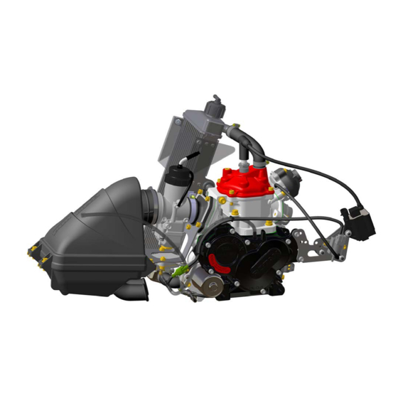
Operator’s Manual ROTAX 125 MAX evo, Junior MAX evo, Mini MAX evo, Micro MAX evo Design of the ROTAX engine types 125 MAX evo, Junior MAX evo, Mini MAX evo and Micro MAX evo 2.1. Single-cylinder two-stroke engine, reed valve controlled, and 125 cm displacement 2.2. -
Page 37: Electric Starter
Operator’s Manual ROTAX 125 MAX evo, Junior MAX evo, Mini MAX evo, Micro MAX evo 2.5. Electric starter By pressing the start button, the circuit between the battery and electric starter will be closed by a relay. The electric starter drives the starter gear on the crankshaft via an intermediate gear with free-wheeling, until the engine starts to run. -
Page 38: Media For Engine Operation
Operator’s Manual ROTAX 125 MAX evo, Junior MAX evo, Mini MAX evo, Micro MAX evo Media for engine operation 3.1. Coolant A mixture of distilled water and aluminum-compatible antifreeze has to be used as coolant. Follow the antifreeze specifications to ensure protection against freezing up to a temperature of -20 °C / -4 °F. - Page 39 Operator’s Manual ROTAX 125 MAX evo, Junior MAX evo, Mini MAX evo, Micro MAX evo When charging the battery, take note of the following: Æ Connect the battery charger to the charging connector (pos. 1). Fig. 1 Æ Connect the battery charging unit to 110-230V, 50-60Hz power supply. During the charging procedure, the charge indicating lamp will light up red.
-
Page 40: Fuel
Operator’s Manual ROTAX 125 MAX evo, Junior MAX evo, Mini MAX evo, Micro MAX evo 3.3. Fuel For engine operation, a mixture of unleaded gasoline of at least ROZ 95 / 91 (RON+MON) / 2 min. and fully synthetic two-stroke oil, mixed at the ratio of 1: 50 (2 % oil) has to be used. -
Page 41: Engine Tuning
Operator’s Manual ROTAX 125 MAX evo, Junior MAX evo, Mini MAX evo, Micro MAX evo Engine tuning Performance graphs In this diagram, the different performance characteristics of the MAX engines are shown. The vertical Y-axis shows the power in kilowatts (kW). The horizontal X-axis shows the rotational speed in revolutions per minute (rpm). - Page 42 Operator’s Manual ROTAX 125 MAX evo, Junior MAX evo, Mini MAX evo, Micro MAX evo The following application for smartphones shows the individual setting of your ROTAX 125 Max engine: The Rotax Max Jetting Guide is an app for Android™ and iOS devices, designed to assist users with setting up the recommended main jet based on the ambient conditions and the type of engine.
- Page 43 Operator’s Manual ROTAX 125 MAX evo, Junior MAX evo, Mini MAX evo, Micro MAX evo Manual set-up: 1. In case no GPS signal or internet connection is available, the necessary data needs to be added manually, which of course requires knowledge about current weather conditions at the race track as well as the altitude.
- Page 44 Operator’s Manual ROTAX 125 MAX evo, Junior MAX evo, Mini MAX evo, Micro MAX evo For further information, a YouTube video is available from the following QR-code: APP Download Please scan the following QR-code for your Android phone: Please scan the following QR-code for your iOS phone: For better understanding and as help for carburetor adjustment, the following figure describes the effect of the various adjustments, depending on the throttle position.
- Page 45 Operator’s Manual ROTAX 125 MAX evo, Junior MAX evo, Mini MAX evo, Micro MAX evo To change the carburetor main jet, proceed as follows: ¿ Note: The carburetor must not be removed from the engine in order to change the jetting.
-
Page 46: Selection Of The Transmission Ratio
Operator’s Manual ROTAX 125 MAX evo, Junior MAX evo, Mini MAX evo, Micro MAX evo ¿ Note: In a disassembled carburetor, the position of the jet needle (pos. 3) can be changed. The standard position of the jet needle is ‘position 2’. If the clip (pos. 4) is set in ‘position 1’, the full mixture in part and full-load will become slightly leaner. - Page 47 Operator’s Manual ROTAX 125 MAX evo, Junior MAX evo, Mini MAX evo, Micro MAX evo In principle, the transmission ratio should be chosen in a way that the engine is mainly operated in a speed range at which the engine performance is well above the driving resistance.
-
Page 48: Exchange Of The Clutch Drum With Chain Sprocket Fitted
Operator’s Manual ROTAX 125 MAX evo, Junior MAX evo, Mini MAX evo, Micro MAX evo 4.3. Exchange of the clutch drum with chain sprocket fitted Æ Remove spark plug connector and spark plug. Æ Fit locking bolt (part no. 277380) right down to stop in spark plug thread. -
Page 49: Change Or Renewal Of The Chain Sprocket On The Clutch Drum
Operator’s Manual ROTAX 125 MAX evo, Junior MAX evo, Mini MAX evo, Micro MAX evo ¿ Note: A smaller thrust washer (pos. 13) is required for the chain sprocket with 11 teeth, in comparison to the use of a chain sprocket with 12, 13 and 14 teeth. -
Page 50: Operating Limits
Operator’s Manual ROTAX 125 MAX evo, Junior MAX evo, Mini MAX evo, Micro MAX evo Operating limits min. coolant temperature 35 °C / 95 °F max. coolant temperature 85 °C / 185 °F p Warning: The engine is only allowed to be run at peak performance after reaching the specified operating temperature. -
Page 51: Engine Start And Operation
Operator’s Manual ROTAX 125 MAX evo, Junior MAX evo, Mini MAX evo, Micro MAX evo Engine start and operation 7.1. Engine start Prior to engine start, verify the following: Fuel tank full. Battery charged and connected. Battery voltage over 12 V. -
Page 52: Stopping The Engine
Operator’s Manual ROTAX 125 MAX evo, Junior MAX evo, Mini MAX evo, Micro MAX evo p Warning: Always wear protective clothing for kart operation (helmet, overall, gloves, shoes, neck and rib guards). p Warning: Do not touch the engine, the radiator or the exhaust system during and immediately after kart operation. -
Page 53: Running-In Procedure For The Engine
Operator’s Manual ROTAX 125 MAX evo, Junior MAX evo, Mini MAX evo, Micro MAX evo 7.3. Running-in procedure for the engine ¢ Attention: Pay attention to safety advice of the kart manufacturer. To ensure that components have the longest possible lifespan, the engine must undergo a defined running-in period at first operation or after a repair of the crankshaft or displacement parts. - Page 54 Operator’s Manual ROTAX 125 MAX evo, Junior MAX evo, Mini MAX evo, Micro MAX evo See Fig. 8. The additional cable is attached to the ground wire. The control of the exhaust valve timing is activated at 7600 rpm. Fig. 8 Variant 2: Additional cable at starter relay See Fig.
- Page 55 Operator’s Manual ROTAX 125 MAX evo, Junior MAX evo, Mini MAX evo, Micro MAX evo Fig. 9 ¿ Note: Either variant 1 or variant 2 has been installed in your engine. Page 54/58 Edition 09/2016...
-
Page 56: Maintenance Schedule For Engine Components
Operator’s Manual ROTAX 125 MAX evo, Junior MAX evo, Mini MAX evo, Micro MAX evo Maintenance schedule for engine components 5 Warning: Non-compliance with the specified maintenance schedule could result in engine damage. Component Inspection Maintenance Checking, remedy Interval chain sprocket... - Page 57 Operator’s Manual ROTAX 125 MAX evo, Junior MAX evo, Mini MAX evo, Micro MAX evo tear-down inspection of engine Inspection following Tear-down inspection must be components after every conducted by an authorized hours operation: piston, distributor. piston pin and piston bearing Renew worn parts as required.
-
Page 58: Transport Of The Kart
Operator’s Manual ROTAX 125 MAX evo, Junior MAX evo, Mini MAX evo, Micro MAX evo Transport of the kart If the carburetor is still filled with fuel, the kart is only allowed to be transported in a horizontal position. If the kart is to be transported in a vertical position, the fuel must be drained from the carburetor first. - Page 59 Operator’s Manual ROTAX 125 MAX evo, Junior MAX evo, Mini MAX evo, Micro MAX evo IMPORTANT INFORMATION (SUMMARY) IMPORTANT RECOMMENDED LITER GAL. SPECIFICATION INFORMATION BRANDS Unleaded fuel of minimum octane level of FUEL 95 ROZ resp. 91 MOZ 2-STROKE OIL...
- Page 60 BRP-Rotax GmbH & Co KG | Rotaxstrasse 1 | 4623 Gunskirchen, Austria | T: +43 7246 601 0 | F: +43 7246 637 0 www.rotax.com | www.rotax-kart.com R and TM are trademarks of BRP-Rotax GmbH & Co KG. © 2016 BRP-Rotax GmbH & Co KG. All rights reserved.
Need help?
Do you have a question about the Rotax 125 MAX evo and is the answer not in the manual?
Questions and answers