
Subscribe to Our Youtube Channel
Related Manuals for BRP ROTAX 916 i A Series


Summary of Contents for BRP ROTAX 916 i A Series
- Page 1 INSTALLATION MANUAL FOR ROTAX ENGINE TYPE 916 i A/C24 SERIES REF NO.: IM-916 i A/C24 | PART NO.: 898874...
- Page 2 These technical data and the information embodied therein Installation Manual completely as it contains important are the property of BRP-Rotax GmbH & CO KG, Austria, acc, safety relevant information. BGBI 1984 no. 448, and shall not, without prior written per- mission of BRP-Rotax GmbH &...
- Page 3 BRP-Rotax INSTALLATION MANUAL Table of Content Chapter INTRO – GENERAL NOTE Chapter LEP – LIST OF EFFECTIVE PAGES Chapter TOA – TABLE OF AMENDMENTS Chapter 00–00–00 – GENERAL NOTE Chapter 10–10–00 – STORAGE AND INSTALLATION Chapter 24–00–00 – ELECTRICAL POWER Chapter 61–00–00 –...
- Page 4 BRP-Rotax INSTALLATION MANUAL INTENTIONALLY LEFT BLANK Page 2 Effectivity: 916 i A / C24 December 01 2023...
- Page 5 ROTAX® authorized distributor or their independent Service Center for ROTAX® aircraft engines. BRP-Rotax GmbH & Co KG (hereinafter “BRP-Rotax“) wishes you much pleasure and satisfaction flying your aircraft powered by this ROTAX® aircraft engine. The structure of the manual follows, whenever possible, the structure of the ATA (Air Transport Association) standards.
- Page 6 BRP-Rotax INSTALLATION MANUAL INTENTIONALLY LEFT BLANK Page 2 Effectivity: 916 i A / C24 December 01 2023...
- Page 7 BRP-Rotax INSTALLATION MANUAL Chapter: LEP LIST OF EFFECTIVE PAGES Each new revision to the Installation Manual will have a new List of Effective Pages. Chapter Page Date Chapter Page Date Title page December 01 2023 December 01 2023 INTRO December 01 2023...
- Page 8 BRP-Rotax INSTALLATION MANUAL Chapter Page Date Chapter Page Date December 01 2023 December 01 2023 December 01 2023 December 01 2023 December 01 2023 December 01 2023 December 01 2023 December 01 2023 December 01 2023 72-60-00 December 01 2023...
- Page 9 BRP-Rotax INSTALLATION MANUAL Chapter Page Date Chapter Page Date December 01 2023 December 01 2023 December 01 2023 December 01 2023 December 01 2023 December 01 2023 December 01 2023 December 01 2023 December 01 2023 December 01 2023 December 01 2023...
- Page 10 BRP-Rotax INSTALLATION MANUAL Chapter Page Date Chapter Page Date December 01 2023 December 01 2023 December 01 2023 December 01 2023 December 01 2023 December 01 2023 December 01 2023 December 01 2023 December 01 2023 December 01 2023 December 01 2023...
- Page 11 BRP-Rotax INSTALLATION MANUAL Chapter: TOA TABLE OF AMENDMENTS Approval* The technical content of this document is approved under the authority of the DOA ref. EASA.21.J.048. July 01 2023 Edition 0/Rev. 0 Obsolete with Revision 1, which is a complete re-revision...
- Page 12 BRP-Rotax INSTALLATION MANUAL Current Chapter Page Date of change Remark Date of Date of Signature approval inclusion approval from authorities Dec. 01 2023 DOA* Dec. 01 2023 DOA* 00-00-00 3,20 Dec. 01 2023 DOA* 24-00-00 Dec. 01 2023 DOA* 61-00-00 Dec.
- Page 13 BRP-Rotax INSTALLATION MANUAL Summary of amendments Summary of the relevant amendments in this context, but without any claim to completeness. Current Chapter Page Date of change Comment December 01 2023 New additional designation of engine type (C24) Effectivity: 916 i A / C24 Edition 0/Rev.
- Page 14 BRP-Rotax INSTALLATION MANUAL INTENTIONALLY LEFT BLANK Page 4 Effectivity: 916 i A / C24 December 01 2023...
-
Page 15: Table Of Contents
BRP-Rotax INSTALLATION MANUAL Chapter: 00–00–00 GENERAL NOTE TOPICS IN THIS CHAPTER General..............................2 Type description............................3 Scope of supply............................4 Auxiliary equipment (optional) ........................5 Abbreviations and terms (depending on respective engine type)............6 Wiring color codes ..........................11 Conversion table ..........................12 Safety notice ............................13 Safety information ..........................14... -
Page 16: General
BRP-Rotax INSTALLATION MANUAL GENERAL Purpose The purpose of this Manual is to provide aircraft manufacturers with technical require- ments (e.g. interface descriptions and limitations) that must be adhered to when installing this type of engine into an aircraft or certifying aircraft powered by this engine type. Fur- thermore it should allow independent ROTAX®... -
Page 17: Type Description
2 for configuration 3 NOTE Conversion of the configuration 2 to configuration 3 and vice versa may be ac- complished by BRP-Rotax Authorized Distributors or their independent Service Centers. Effectivity: 916 i A / C24 00–00–00 Edition 0/Rev. 1... -
Page 18: Scope Of Supply
BRP-Rotax INSTALLATION MANUAL SCOPE OF SUPPLY Basic • 4- stroke-, 4 cylinder horizontally opposed-, spark ignition engine, single central cam- shaft push rods —OHV (Over Head Valve) • Liquid cooled cylinder heads • Ram air cooled cylinders • Dry sump forced lubrication •... -
Page 19: Auxiliary Equipment (Optional)
Any equipment not included as part of the standard engine version and thus not a fix com- ponent of the engine is not in the volume of supply. Components especially developed and tested for this engine are readily available at BRP- Rotax. -
Page 20: Abbreviations And Terms (Depending On Respective Engine Type)
BRP-Rotax INSTALLATION MANUAL ABBREVIATIONS AND TERMS (DEPENDING ON RESPECTIVE ENGINE TYPE) Abbreviations Description Reference to another section center of gravity The drop symbol indicates use of sealing agents, adhesives or lubri- cants (only in the Maintenance Manual Heavy) °C Degrees Celsius (Centigrade) °F... - Page 21 BRP-Rotax INSTALLATION MANUAL Abbreviations Description clockwise counter-clockwise CGSB Canadian General Standards Board DCDI Dual Capacitor Discharge Ignition direct current Design Organisation Approval Department of Transport EASA European Aviation Safety Agency Installation Manual Engine Control Unit Exhaust Gas Temperature Introduction INTRO...
- Page 22 BRP-Rotax INSTALLATION MANUAL Abbreviations Description Illustrated Parts Catalog inch per second iRMT independent ROTAX Maintenance Technician International Standard Atmosphere Kilograms KNOCK Knock sensor Lane A System A of Engine Management System Lane B System B of Engine Management System LOPC Loss of power control MAPS 1 &...
- Page 23 INSTALLATION MANUAL Abbreviations Description Power Take Off Rev. Revision ROTAX® is a trademark of BRP-Rotax GmbH & Co KG Research Octane Number RON 424 ROTAX® Standard 424 s.v. still valid (only Illustrated Parts Catalog) Serial Number Society of Automotive Engineers...
- Page 24 BRP-Rotax INSTALLATION MANUAL Abbreviations Description Connector on Engine Management System wiring harness which serves as an interface for power supply XXXX shows the component serial number 00–00–00 Effectivity: 916 i A / C24 Edition 0/Rev. 1 Page 10 December 01 2023...
-
Page 25: Wiring Color Codes
BRP-Rotax INSTALLATION MANUAL WIRING COLOR CODES Figure 1.2 Effectivity: 916 i A / C24 00–00–00 Edition 0/Rev. 1 Page 11 December 01 2023... -
Page 26: Conversion Table
BRP-Rotax INSTALLATION MANUAL CONVERSION TABLE Units of length: Units of power: 1 mm = 0.03937 in 1 kW = 1.341 hp 1 in = 25.4 mm 1 hp = 0.7457 kW 1 ft = 12 in 1 kW = 1.3596 PS = 0.3048 m... -
Page 27: Safety Notice
The information and descriptions of components and systems contained in this Manual are correct at the time of publication. BRP-Rotax maintains a policy of continuous im- provement of its products without imposing upon itself any obligation to retrofit products previously manufactured. -
Page 28: Safety Information
• Due to the varying designs, equipment and types of aircraft, BRP-Rotax grants no war- ranty on the suitability of its engines use on any particular aircraft. Further, BRP-Rotax... - Page 29 BRP-Rotax INSTALLATION MANUAL Engine operation • The engine must always be operated according to the content of the latest Operators Manual (OM) • To eliminate the risk of injury or damage, ensure any loose equipment or tools are prop- erly secured before starting the engine •...
-
Page 30: Instruction
Accessories This engine must only be operated with accessories supplied, recommended and re- leased by BRP-Rotax. Modifications are only allowed after consent of the engine manufacturer. Spare parts See Illustrated Parts Catalog (IPC), latest issue for the respective engine type. -
Page 31: Technical Documentation
BRP-Rotax INSTALLATION MANUAL TECHNICAL DOCUMENTATION These documents form the instructions ensuring continued airworthiness of ROTAX® air- craft engines. The information contained herein is based on data and experience that are considered ap- plicable for authorized mechanics (iRMT, see MML, Chapter 05–00–00 section “Author- ized Personnel”) under normal conditions for engine removal and installation. - Page 32 BRP-Rotax INSTALLATION MANUAL This symbol informs you of additional references (data sheets, Manuals, etc.) associated with the given subject. Illustrations The illustrations in this Manual are merely sketches and show typical arrangements. They may not represent full detail or the exact shape of the parts but should outline the same or similar function.
-
Page 33: Approval Of Electric And Electronic Components (Equipment Qualification According To Rtca/Do-160)
BRP-Rotax INSTALLATION MANUAL APPROVAL OF ELECTRIC AND ELECTRONIC COMPONENTS (EQUIPMENT QUALIFICATION ACCORDING TO RTCA/DO-160) RTCA/DO-160 defines a series of minimum standard environmental test conditions and applicable test procedures for airborne equipment. The purpose of these tests is to pro- vide a laboratory means of determining the performance characteristics of airborne equip- ment in environmental conditions representative of those which may be encountered in airborne operation of the equipment. - Page 34 BRP-Rotax INSTALLATION MANUAL DO-160G, Section 24 — Icing Test not performed DO-160G, Section 25 — Electrostatic Discharge Cat. A Component System Limit Min. Max. surface tem- - 40 °C (- 40 °F) 80 °C (176 °F) perature limits EGT Sensors (electronic - 40 °C (- 40 °F)
- Page 35 BRP-Rotax INSTALLATION MANUAL Chapter: 10–10–00 STORAGE AND INSTALLATION TOPICS IN THIS CHAPTER Special tools............................3 General..............................4 Engine Storage .............................4 Unpacking the engine ..........................5 Engine handling ............................9 Effectivity: 916 i A / C24 10–10–00 Edition 0/Rev. 1 Page 1 December 01 2023...
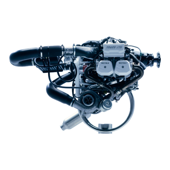
- Page 36 BRP-Rotax INSTALLATION MANUAL Figure 2.1: 916 I A engine 10–10–00 Effectivity: 916 i A / C24 Edition 0/Rev. 1 Page 2 December 01 2023...
-
Page 37: Special Tools
BRP-Rotax INSTALLATION MANUAL SPECIAL TOOLS Description Part number Engine lift set 876040 Effectivity: 916 i A / C24 10–10–00 Edition 0/Rev. 1 Page 3 December 01 2023... -
Page 38: General
ENGINE STORAGE The engine is preserved at BRP-Rotax thus guaranteeing proper protection against corro- sion damage for at least 12 months after the date of delivery from BRP-Rotax. This warranty is subject to the following conditions: • The engine must be stored in the GENUINE-ROTAX®-packing as supplied by BRP- Rotax. -
Page 39: Unpacking The Engine
BRP-Rotax INSTALLATION MANUAL means, but not the only acceptable means, of corrosion treatment. The information in this AC is applicable to aircraft for which the manufacturer has not published corrosion control information. UNPACKING THE ENGINE NOTICE The attachment screws are only for transport and must not be used in the aircraft. - Page 40 BRP-Rotax INSTALLATION MANUAL Pos. Installation location Amount Muffler assy. with resonator assy. Fuel rail 2/4 outlet line / fuel pressure regulator Fuel rail 1/3 feed line Oil inlet/outlet and turbo return line to tank Coolant inlet/outlet Throttle body socket assy.
- Page 41 BRP-Rotax INSTALLATION MANUAL Figure 2.2: Protective covering positions Fuel rail 2/4 outlet line / fuel pressure Muffler assy. with resonator assy. regulator Effectivity: 916 i A / C24 10–10–00 Edition 0/Rev. 1 Page 7 December 01 2023...
- Page 42 BRP-Rotax INSTALLATION MANUAL Oil inlet/outlet and turbo return line to Fuel rail 1/3 feed line tank Throttle body socket assy. Coolant inlet/outlet Air intake socket on turbocharger Connection to / from intercooler Propeller shaft Intercooler Pressure Control Valve (PCV) Governor flange 10–10–00...
-
Page 43: Engine Handling
BRP-Rotax INSTALLATION MANUAL ENGINE HANDLING NOTICE Do not use the fuel lines or the wiring harness for lifting the engine! Attachment The engine may only be lifted on the dedicated attachment points by using the GENUINE- points ROTAX®- engine lift set and a spreader bar with 350 mm (13.78 in) distance between lift- ing points. - Page 44 BRP-Rotax INSTALLATION MANUAL INTENTIONALLY LEFT BLANK Page 10 Effectivity: 916 i A / C24 December 01 2023...
- Page 45 BRP-Rotax INSTALLATION MANUAL Chapter: 24–00–00 ELECTRICAL POWER TOPICS IN THIS CHAPTER System description ..........................4 System limitations ..........................4 Interface description– 916 I Type A......................6 Interface overview ..........................6 Electrical interfaces ..........................6 Mechanical interfaces .......................... 11 Interface description – 916 I Type C24 ....................12 Interface overview.–...
- Page 46 BRP-Rotax INSTALLATION MANUAL 916 i TYPE A Figure 3.1: Internal power supply 24–00–00 Effectivity: 916 i A / C24 Edition 0/Rev. 1 Page 2 December 01 2023...
- Page 47 BRP-Rotax INSTALLATION MANUAL 916 i TYPE C24 Figure 3.2: Internal power supply Effectivity: 916 i A / C24 24–00–00 Edition 0/Rev. 1 Page 3 December 01 2023...
-
Page 48: System Description
BRP-Rotax INSTALLATION MANUAL SYSTEM DESCRIPTION For a detailed system description refer to the latest issue of the Operators Manual (OM). SYSTEM LIMITATIONS NOTICE Consumer cables must NOT be routed alongside the ignition cables. There is a risk of electromagnetic interference. - Page 49 BRP-Rotax INSTALLATION MANUAL 916 i TYPE C 24 Figure 3.4: Regulator temperature measurement area Component temperature measurement 28 V AC-DC Converter assy. area Separation of A connection between regulator plate A (EMS ground) and airframe ground should only EMS and Airframe be done during supply of the EMS System by an external power source (e.g.
-
Page 50: Interface Description- 916 I Type A
BRP-Rotax INSTALLATION MANUAL INTERFACE DESCRIPTION– 916 I TYPE A INTERFACE OVERVIEW Figure 3.5: Fusebox connections, TYPICAL X1 Connector (electrical interface) X2 Connector (electrical interface) X3 Connector (electrical. interface) Regulator Plate A (electrical interface) Fusebox mounting points (mechanical Regulator Plate B (electrical interface) - Page 51 BRP-Rotax INSTALLATION MANUAL AE 5iS_0372 Figure 3.6: X3-Connector: Fusebox side Terminal 1 Terminal 2 Terminal 3 Terminal 1 enables to supply the EMS with an external power source (e.g. in case the in- ternal power supply fails supplying the EMS). Terminal 2 enables powering the EMS dur- ing engine start (until the engine speed is high enough that the internal generator is able to supply the EMS).
- Page 52 BRP-Rotax INSTALLATION MANUAL NOTICE In failure conditions the output voltage can exceed the specified limits. The following measurement is taken at an oil temperature of 135 °C (275 °F). Figure 3.7: Characteristic curve of internal generators 24–00–00 Effectivity: 916 i A / C24 Edition 0/Rev.
- Page 53 BRP-Rotax INSTALLATION MANUAL Fusebox Regula- The regulator plate A needs to be connected with the EMS Ground (cable lugs on the (en- tor A gine-) wiring harness). The terminal is conducted as a M4 screw connection suitable for cable lug according to DIN 46225 (Tightening torque: 1.2 Nm (11 in. lb)). The cable lugs need to be evenly spread onto the three available terminals.
- Page 54 BRP-Rotax INSTALLATION MANUAL Fusebox Regula- The Regulator B needs to be connected with the Airframe Ground. The terminal is con- tor B ducted as a M6 screw connection suitable for cable lug according to DIN 46225 (Tighten- ing torque: 5.9 Nm (52.5 in. in. lb)).
-
Page 55: Mechanical Interfaces
BRP-Rotax INSTALLATION MANUAL MECHANICAL INTERFACES Fusebox mount- ing points Figure 3.11: Fusebox –Connections and dimensions Effectivity: 916 i A / C24 24–00–00 Edition 0/Rev. 1 Page 11 December 01 2023... -
Page 56: Interface Description - 916 I Type C24
BRP-Rotax INSTALLATION MANUAL INTERFACE DESCRIPTION – 916 I TYPE C24 INTERFACE OVERVIEW.– 916 I TYPE C24 916 i TYPE C 24 Figure 3.12: Fusebox connections X1 Connector (electrical interface) X2 Connector (electrical interface) X3 Connector (electrical. interface) Regulator Plate A (electrical interface) -
Page 57: Electrical Interfaces - 916 I Type C24
BRP-Rotax INSTALLATION MANUAL ELECTRICAL INTERFACES – 916 I TYPE C24 916 i TYPE C24 The seals supplied with the Fusebox must be inserted into the X1,X2 and X3 Connector (Fusebox side) to enable a good connection between plug and socket and thus avoid un- necessary vibrations and misalignment of connector pins. - Page 58 BRP-Rotax INSTALLATION MANUAL Fusebox Regula- The regulator plate A needs to be connected with the EMS Ground (ring terminals on the tor A (engine-) wiring harness). The stud has M4 threads suitable for ring terminals according to DIN 46225 or MS25036– 149 (size #8) (tightening torque: 1.2 Nm / 11 in lb). The ring ter- minals need to be evenly spread onto the three available studs.
- Page 59 BRP-Rotax INSTALLATION MANUAL Fusebox The Fusebox needs to connected with the 28 V AC-DC Converter assy.. 916 i TYPE C24 Figure 3.14 Connector to 28 V AC-DC Converter Fusebox assy. Effectivity: 916 i A / C24 24–00–00 Edition 0/Rev. 1...
- Page 60 BRP-Rotax INSTALLATION MANUAL 28 V AC-DC CON- 916 i TYPE C24 VERTER ASSY. Figure 3.15: 28 V AC-DC Converter assy. Orientation of the heat sink NOT to the Firewall firewall Orientation of the heat sink to the firewall Figure 3.16: 28 V AC-DC Converter assy.
- Page 61 BRP-Rotax INSTALLATION MANUAL Generator B Type Connector Function (stator cable Phase 1 of Generator Input from ignition housing) Phase 2 of Generator Input Phase 3 of Generator Input Aircraft 28 V Type Connector Function Bus / Battery 28 V (output for Aircraft)
-
Page 62: Mechanical Interfaces - 916 I Type C24
BRP-Rotax INSTALLATION MANUAL MECHANICAL INTERFACES – 916 I TYPE C24 Fusebox and 916 i TYPE C 24 Converter assy. mounting points Figure 3.17: Fusebox –Connections and dimensions 24–00–00 Effectivity: 916 i A / C24 Edition 0/Rev. 1 Page 18 December 01 2023... - Page 63 BRP-Rotax INSTALLATION MANUAL 916 i TYPE C 24 Figure 3.18: 28 V Converter: Connections and dimensions NOTE 28 V AC-DC converter need to be installed with connector facing down. Effectivity: 916 i A / C24 24–00–00 Edition 0/Rev. 1 Page 19...
-
Page 64: Installation Notes
BRP-Rotax INSTALLATION MANUAL INSTALLATION NOTES General The representation of components in this chapter which are not within scope of the deliv- ery is only symbolic. The design shown in this chapter does not represent a specified exe- cution but should support the understanding of the system. -
Page 65: Battery
BRP-Rotax INSTALLATION MANUAL During engine start (dynamic condition, transient), the two circuits are connected to each other. When the engine is running or when the engine is turned off ( and the Fusebox is not sup- plied with external power), the EMS circuit is electrically isolated from the rest of the aircraft. -
Page 66: Control Elements
BRP-Rotax INSTALLATION MANUAL Interface 916 i Type A Min. Max. Parameter Nominal Nominal Input 12 V Voltage Internal resistance Maximum 10 mΩ at -18 °C (-0.4 °F) Cold Cranking 350 A at -18 °C Ampere (-0.4 °F) (SAE J537) Capacity... - Page 67 BRP-Rotax INSTALLATION MANUAL BATTERY BACKUP CONTROL Parameter Value Contact type Toggle (must not be active during normal operation) Nominal voltage 28 V DC Nominal current 20 A 916 i TYPE C24 START POWER CONTROL Parameter Value Contact type Momentary (must not be active after en-...
- Page 68 BRP-Rotax INSTALLATION MANUAL Figure 3.20: Schematic AC-DC Converter Concept for limiting the charging current: In order to limit the charging current, a series resistor can be used. In following Figure this resistor is called R_I. R_L1 and R_L2 are symbolically shown as load (L= Load) of the 28 V output and define the current flow I_Load.
- Page 69 BRP-Rotax INSTALLATION MANUAL Formula 1 The voltage drop U_R_I is the difference of U_28 V and U_BAT: U_R_I = U_28 V – U_BAT Formula 2 The current flow I_BAT can be calculated as follows: Example 1 – Calculate series resistance U_28 V = 28.9 V, U_BAT = 20 V, I_BAT = 10 A...
- Page 70 BRP-Rotax INSTALLATION MANUAL Figure 3.22: U_R_I = 9 V Figure 3.23: U_R_I = 5 V 24–00–00 Effectivity: 916 i A / C24 Edition 0/Rev. 1 Page 26 December 01 2023...
- Page 71 BRP-Rotax INSTALLATION MANUAL Formula 3 The sum of the currents from I_BAT and I_Load results in I_28 V and must not exceed 27.9 A: I_BAT + I_Lad < 27.9 A Formula 4 I_BAT + I_Load = I_28 V If I_28 V is greater than 27.9 A, the 28 V output is switched off, as already mentioned at the beginning.
-
Page 72: Validation Of Installation
BRP-Rotax INSTALLATION MANUAL VALIDATION OF INSTALLATION General The validation procedures described in this chapter do not claim to be complete. The cor- rect execution and compliance with all given system limitations and interface descriptions as well as with standards and norms given by authorities must be proven by the aircraft manufacturer. - Page 73 BRP-Rotax INSTALLATION MANUAL Separation of 916 i TYPE C24 EMS and Air- Test to ensure there is no continuity between Fusebox Regulator A and Fusebox Regula- frame circuit tor B in static condition (Fusebox is not supplied with power by an external power source).
- Page 74 BRP-Rotax INSTALLATION MANUAL EMS and Air- 916 i TYPE C24 frame circuit Test to ensure there is no warning or caution lamp indication between AC-DC Converter test for AC-DC and any known airframe (aircraft) ground when EMS system is powered (EMS system is...
- Page 75 BRP-Rotax INSTALLATION MANUAL Chapter: 61–00–00 PROPELLER DRIVE TOPICS IN THIS CHAPTER System description ..........................3 System limitations ..........................3 Interface description ..........................4 Interface overview ..........................4 Mechanical interfaces ..........................6 Hydraulic governor for constant speed propeller ..................8 Effectivity: 916 i A / C24 61–00–00 Edition 0/Rev.
- Page 76 BRP-Rotax INSTALLATION MANUAL Figure 4.1: Propeller drive 61–00–00 Effectivity: 916 i A / C24 Edition 0/Rev. 1 Page 2 December 01 2023...
-
Page 77: System Description
BRP-Rotax INSTALLATION MANUAL SYSTEM DESCRIPTION For a detailed System description refer to the latest issue of the Operators Manual (OM). SYSTEM LIMITATIONS Operating limits Refer to latest issue of the Operators Manual (OM). Moment of inertia Min. Max. System Limit... -
Page 78: Interface Description
BRP-Rotax INSTALLATION MANUAL INTERFACE DESCRIPTION INTERFACE OVERVIEW Figure 4.3: Interface (configuration 3) Propeller shaft (mechanical. Interface) Governor flange (hydraulic. Interface) Cover plate NOTE The cover used for delivery needs to be removed before engine operation. The cover may not be used in operational condition. - Page 79 BRP-Rotax INSTALLATION MANUAL Figure 4.4: Interface (configuration 2) Propeller shaft (mechanical. Interface) Effectivity: 916 i A / C24 61–00–00 Edition 0/Rev. 1 Page 5 December 01 2023...
-
Page 80: Mechanical Interfaces
BRP-Rotax INSTALLATION MANUAL MECHANICAL INTERFACES Propeller shaft The propeller in tractor or pusher arrangement must be fitted on the propeller flange in ac- flange cordance with applicable regulations. As required utilize one of three possible pitch circle diameters (P.C.D.) on the flange. - Page 81 BRP-Rotax INSTALLATION MANUAL Interface Parameter Value Pitch circle diameter 80 6x through holes 13 mm (0.51 in.) mm (3.15 in.) Pitch circle diameter 101.6 6x through holes 13 mm (0.51 in.) mm (4 in.) Hub diameter 47 mm (1.85 in.) Gear transmission i=2.54.
-
Page 82: Hydraulic Governor For Constant Speed Propeller
BRP-Rotax INSTALLATION MANUAL HYDRAULIC GOVERNOR FOR CONSTANT SPEED PROPELLER Figure 4.7 Pressure oil line assy. Governor flange Oil inlet Oil outlet 61–00–00 Effectivity: 916 i A / C24 Edition 0/Rev. 1 Page 8 December 01 2023... - Page 83 BRP-Rotax INSTALLATION MANUAL Drive Drive via propeller gearbox. Position of the propeller connection on the governor flange: x-axis [mm/in] y-axis [mm/in] z-axis [mm/in] -206.3 (-8.12) 51.5 (2.03) Connection NOTICE Obey the manufacturers instructions! Technical Data Gear ratio from crankshaft to hydraulic governor is 1.842, i.e. the propeller governor runs at 0.54 times engine speed.
- Page 84 BRP-Rotax INSTALLATION MANUAL INTENTIONALLY LEFT BLANK Page 10 Effectivity: 916 i A / C24 December 01 2023...
- Page 85 BRP-Rotax INSTALLATION MANUAL Chapter: 72–00–00 ENGINE TOPICS IN THIS CHAPTER System description ..........................3 System limitations ..........................7 Interface description ..........................9 Interface overview ..........................9 Mechanical interfaces ..........................9 Installation notes...........................13 Engine suspension ..........................13 Effectivity: 916 i A / C24 72–00–00 Edition 0/Rev. 1...
- Page 86 BRP-Rotax INSTALLATION MANUAL Figure 5.1: Engine, TYPICAL 72–00–00 Effectivity: 916 i A / C24 Edition 0/Rev. 1 Page 2 December 01 2023...
-
Page 87: System Description
BRP-Rotax INSTALLATION MANUAL SYSTEM DESCRIPTION For a detailed System description refer to the latest issue of the Operators Manual (OM). Figure 5.2: Engine side view Engine serial number Propeller flange Connection for return line, both sides Propeller gearbox mandatory Attachment points (for engine transport) - Page 88 BRP-Rotax INSTALLATION MANUAL Figure 5.3: Engine Front view Oil pump housing Oil filter Fuel rail left/right Fuel line assy. Connection for oil feed line Connection for turbo oil return line to tank Wastegate actuator assy. Oil tank (metric or UNF) Crankshaft locking screw position Muffler assy.
- Page 89 BRP-Rotax INSTALLATION MANUAL Figure 5.4: Top view Expansion tank assy. Airbox Fuel pressure regulator Connection for fuel return line Throttle body Connection for fuel feed line Pop off valve Cooling air baffle Dual ignition coils Intercooler Attachment points (for engine lifting) Effectivity: 916 i A / C24 72–00–00...
- Page 90 BRP-Rotax INSTALLATION MANUAL Figure 5.5: Rear view Ignition housing Electric starter Water pump housing Engine suspension frame (ring mount) Solenoid Valve (PCV) Turbocharger assy. 72–00–00 Effectivity: 916 i A / C24 Edition 0/Rev. 1 Page 6 December 01 2023...
-
Page 91: System Limitations
BRP-Rotax INSTALLATION MANUAL SYSTEM LIMITATIONS Operating limits Refer to latest issue of the Operators Manual (OM). Installation The oil system, fuel system and the cooling system are unsuitable for upside-down / in- position verted installation of the engine. System Limit Min. - Page 92 BRP-Rotax INSTALLATION MANUAL Figure 5.7: Propeller and vertical axis TYPICAL Propeller axis The y1-axis must be perpendicular to the longitudinal axis of the aircraft. System Limit Min. Max. Permissible deviation from - 10° + 10° perpendicular (α) 72–00–00 Effectivity: 916 i A / C24 Edition 0/Rev.
-
Page 93: Interface Description
BRP-Rotax INSTALLATION MANUAL INTERFACE DESCRIPTION INTERFACE OVERVIEW Figure 5.8: Attachment points MECHANICAL INTERFACES Attachment Interface Value points Parameter Attachment points x-axis (in) - 253.5 mm (-99.8 in.) - 615 mm (-24.21 in.) 105 mm -105 mm (-4.13 y-axis (in) -71 mm (-2.8 in.) (4.13 in.) - Page 94 BRP-Rotax INSTALLATION MANUAL Interface Value Parameter Attachment points — Thread Max. usable 25 mm (0.98 in.) Thread length Interface Value Parameter Attachment points x-axis (in) - 615 mm (-24.21 in.) - 181 mm (-7.13 in.) 105 mm (4.13 -105 mm (-4.13 90 mm (3.54...
- Page 95 BRP-Rotax INSTALLATION MANUAL Weight Engine component Weight Base engine with gearbox: 75.44 kg (166.3 lb) Governor drive add on weight version 3 0.60 kg (1.32 lb) Cooling air baffle 0.38 kg (0.838 lb) 0.35 kg (0.771 lb) Oil tank 1.50 kg (3.30 lb) Intercooler 1.65 kg (3.65 lb)
- Page 96 BRP-Rotax INSTALLATION MANUAL Centre of gravity Center of gravity (COG) position information only considers the engine itself. Parts without of engine a specific installation position relative to the reference coordinate system are not considered. NOTE All distances are given in relation to the reference coordinate system (P).
-
Page 97: Installation Notes
BRP-Rotax INSTALLATION MANUAL INSTALLATION NOTES General The representation of components in this chapter which are not within scope of the deliv- ery is only symbolic. The design shown in this chapter does not represent a specified exe- cution but should support the understanding of the system. - Page 98 BRP-Rotax INSTALLATION MANUAL m WARNING The hex. screws M10x60 on the attachment points R2 and L2 are only used for transport securing but must never be utilized for engine suspension. See inter- face overview. Therefore, use the ROTAX engine suspension frame and the 4 stated attachment points R2, L2, R3, L3.
- Page 99 BRP-Rotax INSTALLATION MANUAL Chapter: 72–60–00 AIR INTAKE SYSTEM TOPICS IN THIS CHAPTER System description ..........................3 System limitations ..........................3 Interface description ..........................6 Interface overview ..........................6 Mechanical interfaces ..........................7 Pneumatic interfaces ..........................8 Electrical interfaces ..........................9 Installation notes...........................10 Installation overview ..........................10 Effectivity: 916 i A / C24 72–60–00...
- Page 100 BRP-Rotax INSTALLATION MANUAL Figure 6.1: Air intake system 72–60–00 Effectivity: 916 i A / C24 Edition 0/Rev. 1 Page 2 December 01 2023...
-
Page 101: System Description
BRP-Rotax INSTALLATION MANUAL SYSTEM DESCRIPTION For a detailed System description refer to the latest issue of the Operators Manual (OM). SYSTEM LIMITATIONS Induction air Following requirements may be used: intake System Limit Min. Max. Flow rate 400 kg/h Pressure loss between ambi- 10 mbar (0.14 psi) - Page 102 BRP-Rotax INSTALLATION MANUAL Throttle lever Adjust Bowden cable such that throttle valve can be fully opened and closed. Procedure Step Push to “full throttle”, then adjust Bowden cable so that it has 1 mm (0.04 in.) clearance (no tensioning), thereby ensured that throttle valve is com- pletely open.
- Page 103 BRP-Rotax INSTALLATION MANUAL Figure 6.2: Figure shows idle position Spring-loaded screw (idle speed Bowden cable adjustment) Screw with black cap (maximum setting Locking varnish for lowest idle speed) m WARNING Non-compliance can result in serious injuries or death! With throttle lever not connected the throttle valve will remain fully open. The starting position of the throttle valve is therefore full throttle! Therefore never start the engine without connecting the throttle lever first.
-
Page 104: Interface Description
BRP-Rotax INSTALLATION MANUAL INTERFACE DESCRIPTION INTERFACE OVERVIEW Interface overview Figure 6.3: Air intake: Interface overview and components Connection turbocharger to intercooler Air filter connection Air intake hose (pop off valve to throttle Connection intercooler to pop off valve body) Turbocharger... -
Page 105: Mechanical Interfaces
BRP-Rotax INSTALLATION MANUAL Pressure control valve (PCV) Actuator assy. (wastegate) Airbox Intake manifold MECHANICAL INTERFACES Pressure control Interface Parameter Min. Max. valve (PCV) – Tightening torque 1 Nm (9 in. lb) Pressure control valve (PCV) Figure 6.4: Connection and dimensions... -
Page 106: Pneumatic Interfaces
BRP-Rotax INSTALLATION MANUAL PNEUMATIC INTERFACES Airfilter See figure Connection on turbocharger connection Interface Parameter Min. Max. Slip-on length 30 mm (1.18 in.) NOTE Use only filter elements which will not tend to restrict the flow when in contact with water. -
Page 107: Electrical Interfaces
BRP-Rotax INSTALLATION MANUAL Connection on intercooler: Interface Parameter Min. Max. Slip-on length 32 mm (1.26 in.) Intercooler to Interface Parameter Min. Max. overboost valve Slip-on length 18 mm (0.71 in.) Figure 6.6: Overboost valve Connection on throttle body: Install the delivered hose (scope of supply) to the correct side of the overboost valve, recheck if it fits. -
Page 108: Installation Notes
BRP-Rotax INSTALLATION MANUAL INSTALLATION NOTES General The representation of components in this chapter which are not within scope of the deliv- ery is only symbolic. The design shown in this chapter does not represent a specified exe- cution but should support the understanding of the system. - Page 109 BRP-Rotax INSTALLATION MANUAL Chapter: 73–00–00 ENGINE – FUEL AND CONTROL TOPICS IN THIS CHAPTER System description ..........................3 System limitations ..........................3 Interface description ..........................4 Interface overview ..........................4 Hydraulic interfaces ..........................6 Electrical interfaces – 916 I Type A ......................6 Electrical interfaces – 916 I Type C24 .....................7 Mechanical interfaces ..........................7...
- Page 110 BRP-Rotax INSTALLATION MANUAL Figure 7.1: Fuel System 73–00–00 Effectivity: 916 i A / C24 Edition 0/Rev. 1 Page 2 December 01 2023...
-
Page 111: System Description
BRP-Rotax INSTALLATION MANUAL SYSTEM DESCRIPTION For a detailed System description refer to the latest issue of the Operators Manual (OM). SYSTEM LIMITATIONS Operating limits Refer to latest issue of the Operators Manual (OM). Effectivity: 916 i A / C24 73–00–00 Edition 0/Rev. -
Page 112: Interface Description
BRP-Rotax INSTALLATION MANUAL INTERFACE DESCRIPTION INTERFACE OVERVIEW 916 i TYPE A Figure 7.2: Fuel System: Interface overview and components Fuel rail 2/4 outlet line (hydraulic Fuel rail 1/3 feed line (hydraulic Interface) Interface) Fuel line assy. Fuel rail Fuel pump connectors (electrical... - Page 113 BRP-Rotax INSTALLATION MANUAL 916 i TYPE C24 Figure 7.3: Fuel System: Interface overview and components Fuel rail 2/4 outlet line (hydraulic Fuel rail 1/3 feed line (hydraulic Interface) Interface) Fuel line assy. Fuel rail Fuel pump connectors (electrical Injection valves...
-
Page 114: Hydraulic Interfaces
BRP-Rotax INSTALLATION MANUAL HYDRAULIC INTERFACES NOTICE Independent from the ambient conditions (e.g. fuel pressure and temperature) and independent from the used fuel the design of the fuel system must prevent from vapour lock conditions. Vapour lock may result in engine stoppage. -
Page 115: Electrical Interfaces - 916 I Type C24
BRP-Rotax INSTALLATION MANUAL ELECTRICAL INTERFACES – 916 I TYPE C24 Fuel pump 916 i TYPE C 24 connectors Interface Parameter Min. Max. Nominal 12 V 14.5 V 13.8 V Output Voltage (V) Fuel pump assy. (both pumps): @ 12 V = 9.1 A [+/- 2 A]... -
Page 116: Installation Notes
BRP-Rotax INSTALLATION MANUAL INSTALLATION NOTES General The representation of components in this chapter which are not within scope of the deliv- ery is only symbolic. The design shown in this chapter does not represent a specified exe- cution but should support the understanding of the system. -
Page 117: Installation Overview
BRP-Rotax INSTALLATION MANUAL INSTALLATION OVERVIEW Figure 7.4: Fuel system Fuel pump 1 Fuel tank Fuel pump 2 Fine filter Fuel pressure regulator Coarse filter/water trap Effectivity: 916 i A / C24 73–00–00 Edition 0/Rev. 1 Page 9 December 01 2023... -
Page 118: Fuel Lines
BRP-Rotax INSTALLATION MANUAL FUEL LINES To prevent problems with vapour lock, all the fuel lines should be insulated against heat in the engine compartment. It is recommended to route the fuel lines in an appropriate dis- tance from hot engine components and avoid sharp bends. -
Page 119: Coarse Filter
BRP-Rotax INSTALLATION MANUAL NOTE The switching between several fuel tanks at power loss due to fuel shortage should be given within a defined period of time and without falling below the mini- mum performance limit and must be ensured by the aircraft manufacturer. Refer to the latest requirements such as FAR or EASA. -
Page 120: Fuel Pump
BRP-Rotax INSTALLATION MANUAL NOTICE An installation without fine filter may have a significant impact on the proper functional- ity of this engine. FUEL PUMP For reducing the risk of vapor lock, the fuel pump should be placed in a well–ventilated area. -
Page 121: Fuel Shut Off Valve
BRP-Rotax INSTALLATION MANUAL Following points may have a negative impact on the proper functionality of the engine: • A header tank design that enables the re-entry of vapour locks in the suction line • Multi tank system without catch-, header tank... - Page 122 BRP-Rotax INSTALLATION MANUAL INTENTIONALLY LEFT BLANK Page 14 Effectivity: 916 i A / C24 December 01 2023...
- Page 123 BRP-Rotax INSTALLATION MANUAL Chapter: 75–00–00 COOLING SYSTEM TOPICS IN THIS CHAPTER System Description ..........................3 System limitations ..........................3 Interface description ..........................4 Interface overview ..........................4 Hydraulic interfaces ..........................5 Air Cooling interfaces..........................7 Installation notes...........................10 Installation overview ..........................10 Water inlet elbow ..........................12 Expansion tank ...........................12 Coolant hoses .............................13...
- Page 124 BRP-Rotax INSTALLATION MANUAL Figure 8.1: Cooling System 75–00–00 Effectivity: 916 i A / C24 Edition 0/Rev. 1 Page 2 December 01 2023...
-
Page 125: System Description
BRP-Rotax INSTALLATION MANUAL SYSTEM DESCRIPTION For a detailed System description refer to the latest issue of the Operators Manual (OM). SYSTEM LIMITATIONS Operating limits Refer to latest issue of the Operators Manual (OM). m WARNING Non-compliance can result in serious injuries or death! The cooling system must be designed so that operating temperatures will not exceed the maximum values. -
Page 126: Interface Description
BRP-Rotax INSTALLATION MANUAL INTERFACE DESCRIPTION INTERFACE OVERVIEW Figure 8.2: Cooling System – Interfaces Water pump housing Coolant hose Expansion tank assy. Radiator cap Expansion tank connection (hydraulic Water inlet elbow (hydraulic Interface) Interface) Water outlet (hydraulic Interface) Coolant Temperature Sensor (CTS) Cooling air baffle 75–00–00... -
Page 127: Hydraulic Interfaces
BRP-Rotax INSTALLATION MANUAL HYDRAULIC INTERFACES Water inlet elbow Interface Parameter Min. Max. Cooling system pressure (relative) 1.6 bar (232 psi) Cooling water temperature - 20 °C (- 4 °F) 125 °C (257 °F) Cooling water flow (at 5800 rpm) 70 l/h (18.49 USgal/... - Page 128 BRP-Rotax INSTALLATION MANUAL Connection: Inner diameter 25 mm (0.98 in). Expansion tank Interface Parameter Min. Max. connection Slip on length 18 mm (0.71 in.) Figure 8.4: Expansion tank connection 75–00–00 Effectivity: 916 i A / C24 Edition 0/Rev. 1 Page 6...
-
Page 129: Air Cooling Interfaces
BRP-Rotax INSTALLATION MANUAL AIR COOLING INTERFACES Cooling air baffle Figure 8.5: Cooling air baffle position, TYPICAL Position x-axis y-axis z-axis - 142 mm (- 5.59 in.) - 101 mm (- 3.98 in.) - 106 mm (- 4.17 in.) General NOTE... - Page 130 BRP-Rotax INSTALLATION MANUAL Measuring point Figure 8.6: Measuring point TYPICAL Following recommendations should assist the aircraft or fuselage manufacturer in select- ing suitable cooling air ducts: Specification Description Cooling capacity The cooling air baffle must be designed so, that it transfers thermal energy of approx.
- Page 131 BRP-Rotax INSTALLATION MANUAL Figure 8.7: Dimensions of cooling air baffle Effectivity: 916 i A / C24 75–00–00 Edition 0/Rev. 1 Page 9 December 01 2023...
-
Page 132: Installation Notes
BRP-Rotax INSTALLATION MANUAL INSTALLATION NOTES The representation of components in this chapter which are not within scope of the deliv- ery is only symbolic. The design shown in this chapter does not represent a specified exe- cution but should support the understanding of the system. - Page 133 BRP-Rotax INSTALLATION MANUAL 08320 Figure 8.9: Radiator Radiator Water distributor Expansion tank AE_5iS_0884 Figure 8.10: Cooling system schematic Expansion tank Pressure cap Water pump Radiator Overflow bottle Vent Effectivity: 916 i A / C24 75–00–00 Edition 0/Rev. 1 Page 11...
-
Page 134: Water Inlet Elbow
BRP-Rotax INSTALLATION MANUAL WATER INLET ELBOW NOTICE The hoses should be fixed with appropriate clips to prevent loss e.g. with spring type hose clips, such as those used for the coolant hoses between the water pump and cylinder. Figure 8.11: Water inlet elbow... -
Page 135: Coolant Hoses
BRP-Rotax INSTALLATION MANUAL COOLANT HOSES NOTE For proper operation short hoses should be used. Aluminium tubes with an inner diameter of 25 mm (0.98 in) can be used instead of longer hoses. These should have a bulge (1) in order to prevent coolant hoses working loose. -
Page 136: Validation Of Installation
BRP-Rotax INSTALLATION MANUAL VALIDATION OF INSTALLATION General The validation procedures described in this chapter do not claim to be complete. The cor- rect execution and compliance with all given system limitations and interface descriptions as well as with standards and norms given by authorities must be proven by the aircraft manufacturer. - Page 137 BRP-Rotax INSTALLATION MANUAL • Consider cold (winter) and hot (summer) conditions in ground and flight testing. • Check proper dampening of the water radiator and stressfree installation and proper sealing. Effectivity: 916 i A / C24 75–00–00 Edition 0/Rev. 1...
- Page 138 BRP-Rotax INSTALLATION MANUAL INTENTIONALLY LEFT BLANK Page 16 Effectivity: 916 i A / C24 December 01 2023...
- Page 139 BRP-Rotax INSTALLATION MANUAL Chapter: 76–00–00 ENGINE CONTROLS TOPICS IN THIS CHAPTER Special tools............................4 System description ..........................5 System limitations ..........................5 Interface description ..........................6 Interface overview ..........................6 Electrical interfaces ..........................7 Interface overview — 916 I Type C24 ....................10 Electrical interfaces – 916 I Type C24 ....................11 Mechanical interfaces ..........................14...
- Page 140 BRP-Rotax INSTALLATION MANUAL 916 i TYPE A Figure 9.1: Engine management system (EMS), TYPICAL 76–00–00 Effectivity: 916 i A / C24 Edition 0/Rev. 1 Page 2 December 01 2023...
- Page 141 BRP-Rotax INSTALLATION MANUAL 916 i TYPE C24 Figure 9.2: Engine management system (EMS), TYPICAL Effectivity: 916 i A / C24 76–00–00 Edition 0/Rev. 1 Page 3 December 01 2023...
-
Page 142: Special Tools
BRP-Rotax INSTALLATION MANUAL SPECIAL TOOLS Description Part number n.a. Crimping pliers MOLEX 64016-0035/63811-4400 n.a. Disassembly tool MOLEX 63813-1500 n.a. Crimp tool ROTAX® ACDC 28 V X1/X2 and 14 V X1 - SKU: 10–306 n.a. Crimp tool ROTAX® ACDC 28 V X3/X4 - SKU: 10–309 n.a. -
Page 143: System Description
BRP-Rotax INSTALLATION MANUAL SYSTEM DESCRIPTION For a detailed System description refer to the latest issue of the Operators Manual (OM). SYSTEM LIMITATIONS Operating limits Refer to latest issue of the Operators Manual (OM). Valid installation The ECU may be installed either in the engine compartment or in the cockpit. To prevent... -
Page 144: Interface Description
BRP-Rotax INSTALLATION MANUAL INTERFACE DESCRIPTION INTERFACE OVERVIEW 916 i TYPE A Figure 9.3: Engine Management System (EMS) – Interfaces Harness Interface Connector A (HIC A) Harness Interface Connector B (HIC B) (electrical interface) (electrical interface) X1 Connector (electrical interface) X2 Connector (electrical interface) -
Page 145: Electrical Interfaces
BRP-Rotax INSTALLATION MANUAL ELECTRICAL INTERFACES Harness interface The HIC A connector allows powering ECU Lane A and Fuel Pump A. interfaces to Indica- connector A tion elements are described in Chapter 77-00-00. Figure 9.4: HIC A Connector In case the EMS is powered by an external power source or by one of the internal generators: •... - Page 146 BRP-Rotax INSTALLATION MANUAL Terminal (Supply) Terminal (Ground) Interface Min. Max. Nomi- Parameter 1 LANE_SEL_ 7 LANE_SEL_SW_ Nominal 12 V SW_A_1 Voltage Nominal 7.5 A Current 3 SIG_FUEL_ 9 GND_FUEL_ Nominal 12 V PUMP_1 PUMP_1 Voltage Nominal 10 A Current Harness Interface...
- Page 147 BRP-Rotax INSTALLATION MANUAL Figure 9.7: HIC B Connector – Engine controls Min. Max. Nom- Terminal (Supply) Terminal (Ground) Interface inal Parameter LANE_SEL_ LANE_SEL_SW_ Nominal 12 V SW_B_1 Voltage Nominal 7.5 A Current 11 GND_FUEL_ Nominal 12 V SIG_FUEL_ Voltage PUMP_2...
-
Page 148: Interface Overview - 916 I Type C24
BRP-Rotax INSTALLATION MANUAL INTERFACE OVERVIEW — 916 I TYPE C24 916 i TYPE C24 Figure 9.8: Engine Management System (EMS)– Interfaces Harness Interface Connector A (HIC A) Harness Interface Connector B (HIC B) (electrical Interface) (electrical Interface) X1 Connector (electrical Interface) -
Page 149: Electrical Interfaces - 916 I Type C24
BRP-Rotax INSTALLATION MANUAL ELECTRICAL INTERFACES – 916 I TYPE C24 Harness interface 916 i TYPE C24 connector A The HIC A connector allows powering ECU Lane A and Fuel Pump A. interfaces to Indica- tion elements are described in Chapter 77-00-00. - Page 150 BRP-Rotax INSTALLATION MANUAL Terminal (Supply) Terminal (Ground) Interface Min. Max. Nomi- Parameter N LANE_SEL_ P LANE_SEL_SW_ Nominal 12 V SW_A_1 Voltage Nominal 7.5 A Current F SIG_FUEL_ E GND_FUEL_ Nominal 12 V PUMP_1 PUMP_1 Voltage Nominal 10 A Current Harness Interface...
- Page 151 BRP-Rotax INSTALLATION MANUAL Figure 9.12: HIC B Connector – Engine controls Min. Max. Nom- Terminal (Supply) Terminal (Ground) Interface Parameter inal P LANE_SEL_ LANE_SEL_SW_ Nominal 12 V SW_B_1 Voltage Nominal 7.5 A Current SUPP_START_ CONN_START- Nominal 12 V SWITCH ER_REL_SW...
-
Page 152: Mechanical Interfaces
BRP-Rotax INSTALLATION MANUAL MECHANICAL INTERFACES Engine Control Unit (ECU) Figure 9.13: ECU –mounting points Connector socket A1 Connector socket A2 Connector socket B Rubber sleeve 76–00–00 Effectivity: 916 i A / C24 Edition 0/Rev. 1 Page 14 December 01 2023... - Page 153 BRP-Rotax INSTALLATION MANUAL Sensors Ambient Air Pressure and Temperature Sensors (AAPTS 1, 2) Figure 9.14: AAPTS – mounting points Maximum diameter of fastener in the interior of the mounting hole: 6 mm (0.24 in). Only mount sensor with a washer (Ø 10 mm (0.39 in) or with an adequate fastener head diame- ter.
-
Page 154: Installation Notes
BRP-Rotax INSTALLATION MANUAL INSTALLATION NOTES General The representation of components in this chapter which are not within scope of the deliv- ery is only symbolic. The design shown in this chapter does not represent a specified exe- cution but should support the understanding of the system. - Page 155 BRP-Rotax INSTALLATION MANUAL Figure 9.16: Harness Interface Connector B-Schematic Part Function Harness Interface Connector B Lane Select Switch B (-S5) Start Switch (-S6) Fuel Pump Switch A (-S8) Effectivity: 916 i A / C24 76–00–00 Edition 0/Rev. 1 Page 17...
-
Page 156: Installation Overview - 916 I Type C24
BRP-Rotax INSTALLATION MANUAL INSTALLATION OVERVIEW – 916 I TYPE C24 916 i TYPE C24 Figure 9.17: Harness Interface Connector A-Schematic Part Function Harness Interface Connector A Lane Select Switch A (-S4) Fuel Pump Switch 1 (-S7) 76–00–00 Effectivity: 916 i A / C24 Edition 0/Rev. - Page 157 BRP-Rotax INSTALLATION MANUAL Figure 9.18: Harness Interface Connector B-Schematic Part Function Harness Interface Connector B Lane Select Switch B (-S5) Start Switch (-S6) Effectivity: 916 i A / C24 76–00–00 Edition 0/Rev. 1 Page 19 December 01 2023...
-
Page 158: Lane Select Switches
BRP-Rotax INSTALLATION MANUAL LANE SELECT SWITCHES Lane Select Value Interface Parameter Switch A (-S4) Switch type Toggle (normally open) Nominal voltage 28 V Nominal current 7.5 A Number of poles 1-pole Lane Select Interface Parameter Value Switch B (-S5) Switch type... - Page 159 BRP-Rotax INSTALLATION MANUAL Chapter: 77–00–00 ENGINE INDICATING TOPICS IN THIS CHAPTER System description ..........................4 System limitations ..........................4 Interface description ..........................5 Interface overview ..........................5 Electrical interfaces ..........................6 Interface overview – 916 I Type C24 .......................9 Electrical interfaces – 916 I Type C24 ....................10 Installation notes...........................13...
- Page 160 BRP-Rotax INSTALLATION MANUAL 916 i TYPE A Figure 10.1: Engine indication, TYPICAL 77–00–00 Effectivity: 916 i A / C24 Edition 0/Rev. 1 Page 2 December 01 2023...
- Page 161 BRP-Rotax INSTALLATION MANUAL 916 i TYPE C 24 Figure 10.2: Engine indication Effectivity: 916 i A / C24 77–00–00 Edition 0/Rev. 1 Page 3 December 01 2023...
-
Page 162: System Description
BRP-Rotax INSTALLATION MANUAL SYSTEM DESCRIPTION The complete system is volume of supply and is certified together with the engine. For a detailed system description refer to latest issue of the Operators Manual (OM). SYSTEM LIMITATIONS Maintenance CAN The Maintenance CAN must only be used in combination with a B.U.D.S. Aircraft USB-to- CAN converter and B.U.D.S. -
Page 163: Interface Description
BRP-Rotax INSTALLATION MANUAL INTERFACE DESCRIPTION INTERFACE OVERVIEW 916 i TYPE A Figure 10.3: Engine Management System (EMS) – Interfaces Harness Interface Connector A (HIC A) Harness Interface Connector B (HIC B) Electromagnetic shielding of CAN Bus Effectivity: 916 i A / C24 77–00–00... -
Page 164: Electrical Interfaces
BRP-Rotax INSTALLATION MANUAL ELECTRICAL INTERFACES Harness Interface The HIC Connector A is equipped with a Maintenance CAN interface, a Display CAN inter- Connector A face and terminals which can be used to actuate a warning lamp indicating the current sta- tus of the ECU Lane A. - Page 165 BRP-Rotax INSTALLATION MANUAL Harness Interface The HIC Connector B is equipped with a Maintenance CAN interface, a Display CAN inter- Connector B face and terminals which can be used to actuate a warning lamp indicating the current sta- tus of the ECU Lane B. Interfaces to control elements are described in Chapter 76-00-00.
- Page 166 BRP-Rotax INSTALLATION MANUAL Connector: HIC Connector B (included in the engine’s scope of delivery). The HIC Connectors must be mounted according to the procedure prescribed in Chapter 76-00-00. The Display CAN is based on the CAN Aerospace protocol. For detailed interface descrip- tion contact an authorized ROTAX®...
-
Page 167: Interface Overview - 916 I Type C24
BRP-Rotax INSTALLATION MANUAL INTERFACE OVERVIEW – 916 I TYPE C24 916 i TYPE C 24 Figure 10.6: Engine Management System (EMS) – Interfaces Harness Interface Connector A (HIC A) Harness Interface Connector B (HIC B) Electromagnetic shielding of CAN Bus Effectivity: 916 i A / C24 77–00–00... -
Page 168: Electrical Interfaces - 916 I Type C24
BRP-Rotax INSTALLATION MANUAL ELECTRICAL INTERFACES – 916 I TYPE C24 Harness Interface The HIC Connector A is equipped with a Maintenance CAN interface, a Display CAN inter- Connector A face and terminals which can be used to actuate a warning lamp indicating the current sta- tus of the ECU Lane A. - Page 169 BRP-Rotax INSTALLATION MANUAL The Display CAN is based on the CAN Aerospace protocol. For detailed interface descrip- tion contact an authorized ROTAX® Distributor or its independent Service Center. Harness Interface The HIC Connector B is equipped with a Maintenance CAN interface, a Display CAN inter-...
- Page 170 BRP-Rotax INSTALLATION MANUAL The Display CAN is based on the CAN Aerospace protocol. For detailed interface descrip- tion contact an authorized ROTAX® Distributor or its independent Service Center. Electromagnetic The electromagnetic CAN Bus shielding ring terminals need to be connected with the Air- shielding of CAN frame Ground.
-
Page 171: Installation Notes
BRP-Rotax INSTALLATION MANUAL INSTALLATION NOTES General The representation of components in this chapter which are not within scope of the deliv- ery is only symbolic. The design shown in this chapter does not represent a specified exe- cution but should support the understanding of the system. - Page 172 BRP-Rotax INSTALLATION MANUAL Display CAN A Maintenance CAN A 916 i TYPE A Figure 10.10: Harness Interface Connector B – Schematic Part Function Harness Interface Connector B Warning Lamp B (-H2) Warning Lamp B (LED) (-H2 V2) Resistor 1.5 kΩ (-F8) Resistor 1 kΩ...
- Page 173 BRP-Rotax INSTALLATION MANUAL WARNING LAMPS Warning Lamp A, Value Interface Parameter B (-H1, -H2) Nominal voltage Nominal current max. 120 mA Instead of common lamps also LED lamps (-H1 V2, -H2 V2) can be used. In this case a appropriate pre-resistor must be conducted serial to the LED. An additional resistor paral- lel to the LED avoids that the ECU detects an open circuit at this warning lamp.
-
Page 174: Installation Overview - 916 I Type C24
BRP-Rotax INSTALLATION MANUAL INSTALLATION OVERVIEW – 916 I TYPE C24 916 i TYPE C 24 Figure 10.11: Harness Interface Connector A-Schematic Part Function Harness Interface Connector A Warning Lamp A (-H1) Warning Lamp A (LED) (-H1 V2) Resistor 1.5 kΩ (-R6) Resistor 1 kΩ... - Page 175 BRP-Rotax INSTALLATION MANUAL Figure 10.12: Harness Interface Connector B-Schematic Part Function Harness Interface Connector B Warning Lamp B (-H2) Warning Lamp B (LED) (-H2 V2) Resistor 1.5 kΩ (-R8) Resistor 1 kΩ (-R9) Display CAN B Maintenance CAN B Effectivity: 916 i A / C24 77–00–00...
- Page 176 BRP-Rotax INSTALLATION MANUAL Cockpit Airframe side Type Connector Function X5.1 Aircraft GND for Warning Lamps Ground X5.2 Warning Lamp 14 V output EMS/Fuel pump Signal X5.3 Warning Lamp Command Input (Start Power / Signal Battery Backup) X5.4 Warning Lamp 28 V output Aircraft...
- Page 177 BRP-Rotax INSTALLATION MANUAL WARNING LAMPS – 916 I TYPE C24 Warning Lamp A, 916 i TYPE C 24 B (-H1, -H2) Interface Parameter Value Nominal voltage 12 V Nominal current max. 120 mA Instead of common incandescent lamps also LED lamps (-H1 V2, -H2 V2) can be used. In this case a appropriate pre-resistor must be conducted serial to the LED.
- Page 178 BRP-Rotax INSTALLATION MANUAL INTENTIONALLY LEFT BLANK Page 20 Effectivity: 916 i A / C24 December 01 2023...
- Page 179 BRP-Rotax INSTALLATION MANUAL Chapter: 78–00–00 EXHAUST SYSTEM TOPICS IN THIS CHAPTER System description ..........................3 System limitations ..........................3 Interface description ..........................4 Interface overview ..........................4 Mechanical interfaces ..........................5 Effectivity: 916 i A / C24 78–00–00 Edition 0/Rev. 1 Page 1 December 01 2023...
- Page 180 BRP-Rotax INSTALLATION MANUAL Figure 11.1: Exhaust system, TYPICAL 78–00–00 Effectivity: 916 i A / C24 Edition 0/Rev. 1 Page 2 December 01 2023...
-
Page 181: System Description
BRP-Rotax INSTALLATION MANUAL SYSTEM DESCRIPTION The complete system is volume of supply and is certified together with the engine. For a detailed system description refer to latest issue of the Operators Manual (OM). SYSTEM LIMITATIONS Operating limits Refer to latest issue of the Operators Manual (OM). -
Page 182: Interface Description
BRP-Rotax INSTALLATION MANUAL INTERFACE DESCRIPTION INTERFACE OVERVIEW Figure 11.2: Exhaust interfaces Muffler assy. Exhaust pipe Exhaust manifold assy. Resonator assy. 78–00–00 Effectivity: 916 i A / C24 Edition 0/Rev. 1 Page 4 December 01 2023... -
Page 183: Mechanical Interfaces
BRP-Rotax INSTALLATION MANUAL MECHANICAL INTERFACES Exhaust tail pipe Figure 11.3: Exhaust position Value Interface Parameter Exhaust elbow material X15CrNiSi20-12 NOTE The resonator can be rotated as desired, but the orientation can only be changed before initial operation. Afterwards M5x12 screws must not be removed. - Page 184 BRP-Rotax INSTALLATION MANUAL Figure 11.4: Position of the M5x12 screws V-band clamp assy. Muffler M5x12 screws 78–00–00 Effectivity: 916 i A / C24 Edition 0/Rev. 1 Page 6 December 01 2023...
- Page 185 BRP-Rotax INSTALLATION MANUAL Chapter: 79–00–00 LUBRICATION SYSTEM TOPICS IN THIS CHAPTER System description ..........................3 System limitations ..........................3 Crankcase pressure measurement ......................3 Measuring of the vacuum ........................5 Oil hose requirements..........................7 Interface description ..........................8 Interface overview ..........................8 Oil tank dimensions ..........................8 Oil tank interfaces..........................10 Oil pump .............................
- Page 186 BRP-Rotax INSTALLATION MANUAL Figure 12.1: Lubrication system, TYPICAL 79–00–00 Effectivity: 916 i A / C24 Edition 0/Rev. 1 Page 2 December 01 2023...
-
Page 187: System Description
BRP-Rotax INSTALLATION MANUAL SYSTEM DESCRIPTION For a detailed System description refer to the latest issue of the Operators Manual (OM). SYSTEM LIMITATIONS Operating limits Refer to latest issue of the Operators Manual (OM). m WARNING Non-compliance can result in serious injuries or death! The lubrication system must be designed such that the permissible operating tempera- tures and maximum values are not exceeded. - Page 188 BRP-Rotax INSTALLATION MANUAL NOTICE Do not remove the magnetic plug for prolonged periods and do not use the meas- urement equipment during flight operations. A pressure sensor (pressure gauge with liquid damping) can be fitted instead of the mag- netic plug or the crankshaft locking screw. The magnetic plug or the crankshaft locking screw is removed and the pressure sensor is fitted.
-
Page 189: Measuring Of The Vacuum
BRP-Rotax INSTALLATION MANUAL MEASURING OF THE VACUUM Figure 12.3: Measuring of the vacuum Oil pump housing Suction oil hose Pressure gauge with liquid damping for vacuum Measure the vacuum in the suction oil hose- from the oil tank via the oil cooler to the en- gine oil pump - at a distance of max. - Page 190 BRP-Rotax INSTALLATION MANUAL m WARNING Non-compliance can result in serious injuries or death! The vacuum must be verified over the complete engine operation range. If the oil is cold, the flow resistance increases, which means that not enough oil will flow on the suction side.
-
Page 191: Oil Hose Requirements
BRP-Rotax INSTALLATION MANUAL m WARNING Non-compliance can result in serious injuries or death! At higher positioning of the oil tank, oil might leak through clearances at bearings back into crankcase. Oil tank will be empty and all oil will be in the crankcase. If fitted too low it might happen that the oil filter will be drained. -
Page 192: Interface Description
BRP-Rotax INSTALLATION MANUAL INTERFACE DESCRIPTION INTERFACE OVERVIEW Figure 12.5: Lubrication system interfaces Oil return outlet (hydraulic Oil pump inlet (hydraulic interface) interface) Oil return outlet (turbocharger) Oil tank in- and outlets (hydraulic (hydraulic interface) interface) Oil filter (hydraulic interface) OIL TANK DIMENSIONS Oil tank The oil tank must be mounted by using appropriate clamps. - Page 193 BRP-Rotax INSTALLATION MANUAL Figure 12.6: Oil tank dimensions Oil dipstick Oil tank Plug screw M12x12 Oil tank cover Gasket ring C12x18 Profile clamp 163 Oil tank cover assy. (metric or UNF) Effectivity: 916 i A / C24 79–00–00 Edition 0/Rev. 1...
-
Page 194: Oil Tank Interfaces
BRP-Rotax INSTALLATION MANUAL OIL TANK INTERFACES Oil tank inlet and outlet Figure 12.7: Oil tank interfaces Oil tank inlet Oil tank outlet Oil tank inlet (turbo charger) Vent socket NOTE The oil tank cover is also marked: IN — oil tank inlet, OUT — oil tank outlet. -
Page 195: Oil Pump
BRP-Rotax INSTALLATION MANUAL Vent socket Interface Parameter Value Outside diameter 8 mm (0.31 in.) Slip–on length 15 mm (0.59 in.) m WARNING In any case the vent fitting must ensure a release of pressure from the oil tank at any time. Otherwise oil could emerge into the turbo housing which conveys through the exhaust. - Page 196 BRP-Rotax INSTALLATION MANUAL NOTICE Both oil return outlets need to be used. Only the oil return lines on magneto side must be used. The hoses must have approx. the same length. Figure 12.8: Oil return outlets Oil return outlet 79–00–00 Effectivity: 916 i A / C24 Edition 0/Rev.
- Page 197 BRP-Rotax INSTALLATION MANUAL Interface Parameter Value Screw socket M18 x 1.5 or 3/4–16 UNF Tightening torque 25 Nm (18 ft.lb) Oil return outlet The oil return outlet (turbo charger) must be connected directly with the oil tank inlet (turbo (turbo charger) charger).
-
Page 198: Installation Notes
BRP-Rotax INSTALLATION MANUAL INSTALLATION NOTES General The representation of components in this chapter which are not within scope of the deliv- ery is only symbolic. The design shown in this chapter does not represent a specified exe- cution but should support the understanding of the system. -
Page 199: Installation Overview
BRP-Rotax INSTALLATION MANUAL INSTALLATION OVERVIEW Figure 12.10: Lubrication system overview Engine circuit Turbocharger return line OIL THERMOSTAT When operating at low temperatures the installation of an oil thermostat parallel to the oil cooler is highly recommended. The advantages are safe oil pressure after cold start and prevention of fuel and water accumulation in the oil. -
Page 200: Oil Lines
OIL RADIATOR (OPTIONAL) Essential parts of the cooling system, such as radiator, etc., are available for this engine from BRP-Rotax. See also SI-PAC-014.Oil radiator /-sets. m WARNING Non-compliance can result in serious injuries or death! The furnishing of proof in accordance to the latest FAR and EASA, has to be conducted by the aircraft manufacturer. - Page 201 BRP-Rotax INSTALLATION MANUAL Specifications of the oil radiator The radiator must be designed to dissipate approx. 30 kW (28.43 BTU/s) of thermal en- ergy at take-off performance. Weight: max. 0.82 kg (1.8 lb) for oil radiator “extra large”. NOTICE The oil radiator must not restrict oil flow. Test system as per section “Checking the oil circuit”.
-
Page 202: Filling And Purging The Oil System
BRP-Rotax INSTALLATION MANUAL FILLING AND PURGING THE OIL SYSTEM Introduction Ensure that oil lines are connected correctly and secured. Also ensure that the oil cooler (if fitted) is in the suction line between the oil tank and the oil pump, see following figure. - Page 203 BRP-Rotax INSTALLATION MANUAL 13. Carefully check all lubrication system connections, lines and clamps for leaks and tightness. ENVIRONMENTAL NOTE Protect the environment! Do not spill oil and pay attention for adequate disposal. Figure 12.12: Setup for venting the oil system, TYPICAL...
-
Page 204: Validation Of Installation
BRP-Rotax INSTALLATION MANUAL VALIDATION OF INSTALLATION General The validation procedures described in this chapter do not claim to be complete. The cor- rect execution and compliance with all given system limitations and interface descriptions as well as with standards and norms given by authorities must be proven by the aircraft manufacturer. - Page 205 BRP-Rotax INSTALLATION MANUAL Chapter: 80–00–00 STARTING TOPICS IN THIS CHAPTER System description ..........................3 System limitations ..........................3 Interface description ..........................4 Interface overview ..........................4 Electrical interfaces ..........................4 Installation notes.............................6 Installation overview ..........................6 Wiring..............................7 Starter relay assy. technical data ......................9 Validation of installation ........................11 Effectivity: 916 i A / C24 80–00–00...
- Page 206 BRP-Rotax INSTALLATION MANUAL Figure 13.1: Starting 80–00–00 Effectivity: 916 i A / C24 Edition 0/Rev. 1 Page 2 December 01 2023...
-
Page 207: System Description
BRP-Rotax INSTALLATION MANUAL SYSTEM DESCRIPTION For a detailed System description refer to the latest issue of the Operators Manual (OM). SYSTEM LIMITATIONS Operating limits Refer to latest issue of the Operators Manual (OM). Ambient temperatures System Limit Min. Max. Electric Starter - 40 °C (- 40 °F) -
Page 208: Interface Description
BRP-Rotax INSTALLATION MANUAL INTERFACE DESCRIPTION INTERFACE OVERVIEW Figure 13.2: Starter interfaces Negative terminal Positive terminal ELECTRICAL INTERFACES Positive 916 i TYPE A terminal Interface Parameter Min. Max. Nominal Input voltage: 12 V Input load:* 20 A 350 A * for resistance of starter circuit Rsmax = <20 mOhm... - Page 209 BRP-Rotax INSTALLATION MANUAL Positive 916 i TYPE C24 terminal Interface Parameter Min. Max. Nominal Input voltage: 24 V Input load:* 20 A 350 A * for resistance of starter circuit Rsmax = <20 mOhm The terminal must be conducted as M5 screw connection suitable for cable lug according to DIN 46225.
-
Page 210: Installation Notes
BRP-Rotax INSTALLATION MANUAL INSTALLATION NOTES General The representation of components in this chapter which are not within scope of the deliv- ery is only symbolic. The design shown in this chapter does not represent a specified exe- cution but should support the understanding of the system. -
Page 211: Wiring
BRP-Rotax INSTALLATION MANUAL 916 i TYPE C24 Figure 13.4: Engine starting circuit WIRING The minimum cable cross-section for the line from the battery to the starter relay and from there to the electric starter and for the ground line (start system) depends on the cable length “I“(= Sum of the supply line and ground line of the electric starter) and is recom-... - Page 212 BRP-Rotax INSTALLATION MANUAL I [m] I [ft] ] AWG min. min. max. max. min. 9<I<9.5 29.5<I<31.2 48.469 0.075 0.109 9.5<I<10 31.2<I<32.8 51.02 0.079 0.109 The internal resistance of the battery and the resistance of the electrical system (wires, contact points, relay contacts) largely determine the performance of the starting system.
-
Page 213: Starter Relay Assy. Technical Data
BRP-Rotax INSTALLATION MANUAL STARTER RELAY ASSY. TECHNICAL DATA NOTICE Activation of starter relay limited to short duration. The duty cycle over an inter- val of 4 minutes is 25%. Figure 13.5: Starter relay Control wiring Main current connections Mounting point... - Page 214 BRP-Rotax INSTALLATION MANUAL Grounding Figure 13.6: Starter relay Starter relay Hex. nut M6 Washer 6.4 Terminal S Ground Bolt/screw Terminal B Terminal M Wiring harness (Engine) 80–00–00 Effectivity: 916 i A / C24 Edition 0/Rev. 1 Page 10 December 01 2023...
-
Page 215: Validation Of Installation
BRP-Rotax INSTALLATION MANUAL VALIDATION OF INSTALLATION General The validation procedures described in this chapter do not claim to be complete. The cor- rect execution and compliance with all given system limitations and interface descriptions as well as with standards and norms given by authorities must be proven by the aircraft manufacturer. - Page 216 BRP-Rotax INSTALLATION MANUAL INTENTIONALLY LEFT BLANK Page 12 Effectivity: 916 i A / C24 December 01 2023...
- Page 217 BRP-Rotax INSTALLATION MANUAL Chapter: 92–00–00 WIRING DIAGRAMS TOPICS IN THIS CHAPTER General This Chapter contains the wiring diagrams for each relevant engine system installation. The wiring diagrams have the same numbering system and abbreviations as used in this Manual Title Drawing Rev.
- Page 218 AmbientAirPressureAndTemperature_Sensor_1 AmbientAirPressureAndTemperature_Sensor_2 OilPressure_Sensor OilTemperature_Sensor ExhaustGasTemperature_Sensor_1-3 Boost_Pressure_Sensor_1 Boost_Pressure_Sensor_2 Solenoid_Valve_A_B_C PCV_C PCV_A PCV_B CAN_LOW_1_LA CAN_GND_1_LA Ring Terminal P8-14R-Q INJ_1 AAPTS_1 AAPTS_2 EGTS_1-3 BPS_1 BPS_2 MaintenancePort_Lane_A PCV_C PCV_A PCV_B SIG_INJ_1 AWG 18 SUPP_INJ_1 AWG 18 CAN_HIGH_1_LA 1 LANE_SEL_SW_A_1 Injector_1 AWG 16 2 SUPP_WARN_LAMP_A AWG 18 3 SIG_FUEL_PUMP_1 INJ_3...
- Page 219 BRP-Rotax INSTALLATION MANUAL INTENTIONALLY LEFT BLANK Page 2 Effectivity: 916 i A / C24 December 01 2023...
- Page 220 BRP-Rotax INSTALLATION MANUAL Index Fuel pump ............12 Fuel shut off valve ..........13 Abbreviations............6 Fuel system, overview ...........9 Air cooling interfaces ..........7 Fuel tank ............12 Approval of electric and electronic components ..19 Auxiliary equipment ..........5 Gascolator............11 General ..............2 Battery ...............21 Grounding cables..........20...
- Page 221 BRP-Rotax INSTALLATION MANUAL Oil tank interfaces ..........10 System Limitations ..........3 Oil thermostat .............15 Table of amendments ..........1 Pneumatic interfaces ..........8 Technical documentation ........17 Positive terminal............4 Terms..............6 Propeller governor, hydraulic........8 Type description............3 Purging line, Requirements ........7 Validation of installation .......28, 14, 20, 11 Return line ............10...
- Page 223 Engine serial no. Type of aircraft Aircraft registration no. Rotax® authorized distributor FLYROTAX.COM ® and TM are trademarks of BRP-Rotax GmbH & Co KG. 2023 BRP-Rotax GmbH & Co KG. All rights reserved. ©...
Need help?
Do you have a question about the ROTAX 916 i A Series and is the answer not in the manual?
Questions and answers