Table of Contents
Advertisement
Quick Links
Advertisement
Table of Contents

Related Manuals for Silicon Graphics 230

Summary of Contents for Silicon Graphics 230
- Page 1 ® Silicon Graphics 230 Visual Workstation User’s Guide 007-4263-001...
- Page 2 United States. Contractor/manufacturer is Silicon Graphics, Inc., 1600 Amphitheatre Pkwy., Mountain View, CA 94043-1351. TRADEMARKS Silicon Graphics is a registered trademark and SGI and the SGI logo are trademarks of Silicon Graphics, Inc. Pentium is a registered trademark of Intel Corporation. Acer is a registered trademark of Acer Inc.
- Page 3 Record of Revision Version Description March 2000 Original Publication 007-4263-001...
-
Page 5: Table Of Contents
Contents Figures . . ix Tables . . xiii About This Guide. . xv Obtaining Publications . xv Reader Comments . . xvi System Setup . External Structure . Internal Structure . Pre-installation Instructions . Connecting External Devices . Installation of Customer Replaceable Components . . - Page 6 Contents System Board . . 57 Overview . 57 Processor . 57 Memory. . 58 System Chipsets . 58 Expansion Slots . 59 Hardware Management Support . 59 Major Components . . 60 System Board Layout . . 61 System Component Installation . .
- Page 7 Contents Advanced Options. .103 Memory/Cache Options . .103 PnP/PCI Options . .105 Load Default Settings . .108 Abort Settings Change .109 Exit Setup . .110 Connector Pinouts .111 Keyboard Port . .112 Mouse Port . .113 Video-Out Ports .114 DB15 HD Port . .114 Serial Ports .
- Page 8 Contents Laser compliance statement . CLASS 1 LASER PRODUCT . APPAREIL A LASER DE CLASSE 1. LUOKAN 1 LASERLAITE LASER KLASSE 1 . PRODUCTO LÁSER DE LA CLASE I . VARO! LAVATTAESSA OLET ALTTINA LASERSÅTEILYLLE. Lithium battery statement . Index. viii 007-4263-001...
-
Page 9: Figures
Figures Front Bezel . Figure 1-1 Rear Panel . Figure 1-2 I/O Ports Figure 1-3 Internal Structure . Figure 1-4 5.25-inch and 3.5-inch Drive Bays Figure 1-5 Connecting AC Power Cable . Figure 1-6 Connecting Keyboard, Mouse, and Ethernet Cable . - Page 10 Figures Removing Expansion Card. . 40 Figure 2-18 Location of the Retaining Screw for the Expansion Slot Filler Plate . 41 Figure 2-19 Installing Expansion Card . . 42 Figure 2-20 Location of System Board Screw . . 44 Figure 2-21 Removing Retaining Bracket from System Board .
- Page 11 Figures Supervisor Password Screen . .100 Figure 4-12 Exit Setup Screen . .101 Figure 4-13 Exit Setup Screen . .101 Figure 4-14 User Password Screen . .102 Figure 4-15 Advanced Options Screen . .103 Figure 4-16 Memory/Cache Options Screen . .104 Figure 4-17 PnP/PCI Configuration...
-
Page 13: Tables
Tables Tables Connector descriptions . 62 Table 3-1 Multi Connector details . 64 Table 3-2 Frequency setting . . 65 Table 3-3 System Error Messages . 72 Table 3-4 System Information . 80 Table 4-1 Product Information . 82 Table 4-2 Disk Drives Parameters . -
Page 15: About This Guide
About This Guide This guide provides information on using and administering a Silicon Graphics 230 Visual Workstation. The following topics are covered in this manual: • Chapter 1, “System Setup,” describes how to prepare the system for installation and how to connect it to its peripheral devices. -
Page 16: Reader Comments
About This Guide Reader Comments If you have comments about the technical accuracy, content, or organization of this document, please tell us. Be sure to include the title and document number of the manual with your comments. (Online, the document number is located in the front matter of the manual. -
Page 17: System Setup
Chapter 1 System Setup This chapter details the steps required to install a Silicon Graphics 230 Visual Workstation. It describes how to prepare the system for installation and how to connect it to its peripheral devices. It also provides a general description of the external and internal structure of the Silicon Graphics 230 Visual Workstation. -
Page 18: External Structure
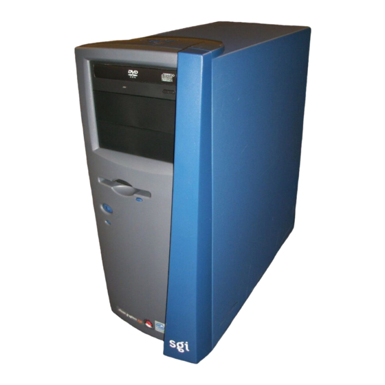
1: System Setup External Structure This section describes the external features of the system housing (the front bezel and the rear panel). • Front Bezel As illustrated in Figure 1-1, the floppy drive and up to three 5.25-inch devices are accessible from the front panel. -
Page 19: Figure 1-2 Rear Panel
External Structure • Rear Panel As shown in Figure 1-2, the rear panel includes the AC power input socket, the rear system fans, six expansion slots, and the I/O panel. Figure 1-3 shows a detailed view of the I/O panel. Power supply rear screws Locking loop... -
Page 20: Figure 1-3 I/O Ports
1: System Setup Mouse port Keyboard port USB ports Serial port 1 Parallel port Serial port 2 Ethernet port Audio-In port MIC In port Line-Out port DVI-D-port S-Video-Out port Monitor port Figure 1-3 I/O Ports 007-4263-001... -
Page 21: Internal Structure
Internal Structure Internal Structure This section describes the location of the main components inside the Silicon Graphics 230 Visual Workstation chassis as illustrated in Figure 1-4. Power supply Tamper switch Rear fan System disk AGP 4X slot Front fan PCI slots... - Page 22 1: System Setup • The Silicon Graphics 230 Visual Workstation has three 5.25-inch and four 3.5-inch drive bays, as shown in Figure 1-5. All three 5.25-inch drive bays are externally accessible from the front panel. Two of the 3.25-inch drive bays are located on the front panel—the other two are housed and accessible inside the chassis.
-
Page 23: Figure 1-5 5.25-Inch And 3.5-Inch Drive Bays
Internal Structure 5.25" drive bay (CD-ROM drive installed) 5.25" drive bay 5.25" drive bay 3.5" drive bay 3.5" drive bay (floppy disk drive installed) Internal 3.5" drive slot Internal 3.5" drive bay (hard disk drive installed) 5.25-inch and 3.5-inch Drive Bays Figure 1-5 007-4263-001... -
Page 24: Pre-Installation Instructions
1: System Setup Pre-installation Instructions Before proceeding with the installation, select a suitable site that will allow for continued maximum performance of the unit, and for easy access to its components. Consider the following questions before selecting a site for the system: •... -
Page 25: Connecting External Devices
Connecting External Devices Connecting External Devices Follow the instructions in this section to connect the system to the power source and to its external peripheral devices. Connect the AC power cable to the system as shown in Figure 1-6. Caution: The power supply is switch-selectable for 110V or 220V AC power. Verify the voltage setting before plugging in the power cord. -
Page 26: Figure 1-7 Connecting Keyboard, Mouse, And Ethernet Cable
1: System Setup 2. Connect the keyboard and mouse to the system as shown in Figure 1-7. 3. Connect the Ethernet cable to the system as shown in Figure 1-7. The built-in Ethernet port is designed for use with 10-Base-T or 100-Base-TX Ethernet networks and will automatically switch to the proper speed. -
Page 27: Figure 1-8 Connecting Db15 Hd Video Cable
Connecting External Devices 4. Connect a DB15 HD video cable to the system as shown in Figure 1-8. 5. Connect the monitor to the power source as shown in Figure 1-8. Connecting DB15 HD Video Cable Figure 1-8 007-4263-001... - Page 28 1: System Setup 6. Follow these directions to connect speakers to the system. Figure 1-9 illustrates the procedure: Note: Speakers on your Silicon Graphics 230 Visual Workstation may be an optional feature. Read the operating precautions in the Speaker Installation Guide before connecting the speakers to the system.
-
Page 29: Figure 1-9 Connecting Speakers
Connecting External Devices Input Signal Output Left speaker Subwoofer 18.5 Figure 1-9 Connecting Speakers 007-4263-001... -
Page 30: Figure 1-10 I/O Panel
1: System Setup 7. Connect other external devices to their respective ports. Refer to Figure 1-10 for a detailed view of the I/O panel. Mouse port Keyboard port USB ports Serial port 1 Parallel port Serial port 2 Ethernet port Audio-In port MIC In port Line-Out port... -
Page 31: Installation Of Customer Replaceable Components
Chapter 2 Installation of Customer Replaceable Components This chapter describes how to install customer replaceable components. This includes the removal and replacement of 3.5-inch and 5.25-inch drives, the power supply, the fans, expansion cards, the system board, and the I/O gasket. A description of the steps to be taken to prepare the system for installation is provided first. -
Page 32: Pre-Installation Instructions
2: Installation of Customer Replaceable Components Pre-installation Instructions The following steps describe how to prepare the system for the removal and installation of customer replaceable components: Turn off the system before opening the side panel. 2. Unplug the AC power cable from the wall socket and from the power supply. 3. -
Page 33: Figure 2-2 Removing Bezel
Pre-installation Instructions 4. If you will need access to the front panel drives, you will have to remove the bezel. Follow these instructions if you need to remove the bezel: Remove the side panel as explained in Step 3. b. Release the four tabs on the side of the bezel by gently lifting them out of the chassis while at the same time pulling the bezel away from the system. -
Page 34: Removing And Installing Drives
filler plate snaps into place. The following instructions describe how to install 5.25-inch drives: All drives are mounted on snap-on drive rails. The Silicon Graphics 230 Visual Workstation comes with two sets of spare 5.25-inch drive rails. The spare drive rails are located inside the chassis on the side of the 5.25-inch drive bays. -
Page 35: Figure 2-3 Mounting Drive Rails To 5.25-Inch Drives
Removing and Installing Drives 3. To mount a drive rail to the drive, place one end of the drive rail wire clip into its drive screw hole. Gently push on the middle of the drive rail until the other end of the wire clip snaps into its screw hole. -
Page 36: Figure 2-4 Removing Bezel Blanking Plate
2: Installation of Customer Replaceable Components 6. The Silicon Graphics 230 Visual Workstation comes with two plastic blanking plates installed on the bezel. The following directions show how to remove and install the bezel blanking plates: • To remove a blanking plate, push on the release mechanism at one end of the blanking plate and pull the blanking plate out of the bezel. -
Page 37: Figure 2-5 Installing Bezel Blanking Plate
Removing and Installing Drives • To install a blanking plate, insert one end of the blanking plate into its retaining notches, then push the other end until it snaps into place. See Figure 2-5 for an illustration of the procedure. Installing Bezel Blanking Plate Figure 2-5 7. -
Page 38: Removing And Installing A 3.5-Inch Drive In The Front-Access Drive Cage
2: Installation of Customer Replaceable Components Removing and Installing a 3.5-inch Drive in the Front-Access Drive Cage The following instructions describe how to remove 3.5-inch drives from the front-access drive cage: Remove the side panel and the bezel as described in “Pre-installation Instructions” on page 16. -
Page 39: Figure 2-7 Detaching 3.5-Inch Drive Filler Plate
Removing and Installing Drives The upper 3.5-inch front access drive bay is covered with a detachable filler plate. Follow these instructions to detach the filler plate: Note: Once removed, the filler plate cannot be re-installed. • The lower 3.5-inch drive bay needs to be empty to proceed with the removal of the filler plate;... - Page 40 Note: Use of 10,000 RPM drives in the front-access drive cage is not recommended. All drives are mounted on snap-on drive rails. The Silicon Graphics 230 Visual Workstation comes with two sets of spare 3.5-inch drive rails. One set of spare 3.5-inch drive rails is located inside the chassis on the side of the 5.25-inch drive...
-
Page 41: Figure 2-8 Mounting Drive Rails To 3.5-Inch Drives
Removing and Installing Drives Mounting Drive Rails to 3.5-inch drives Figure 2-8 5. To mount a drive in the front-access drive cage, place the drive in the 3.5-inch selected drive bay and slide the drive into the bay until the rails snap into place. Note: For a drive to be correctly mounted in the front-access drive cage, it must be installed right side up. -
Page 42: Removing And Installing A 3.5-Inch Drive In The Internal Drive Cage
Note: Only low-profile (i.e., one-inch) drives can be mounted in the internal drive cage. All drives are mounted on snap-on drive rails. The Silicon Graphics 230 Visual Workstation comes with two sets of spare 3.5-inch drive rails. One set of spare 3.5-inch drive rails is located inside the chassis on the side of the 5.25-inch drive... -
Page 43: Figure 2-9 Mounting Drives In The Internal Drive Cage
Removing and Installing Drives 5. To mount a drive in the internal drive cage, place the drive upside down in 3.5-inch the selected drive bay and slide the drive into the bay until the rails snap into place. Figure 2-9 shows how to install the drive correctly. Caution: For a drive to be correctly mounted in the internal drive cage, it must be installed upside down. - Page 44 2: Installation of Customer Replaceable Components 6. Connect cables to the drive. 7. Replace the side panel as described in “Post-installation Instructions” on page 54. 007-4263-001...
-
Page 45: Replacing The Power Supply
Replacing the Power Supply Replacing the Power Supply Follow the instructions in this section to remove and replace the power supply. Warning: Do not open the power supply. Even when unplugged, it may contain dangerous voltages. There are no user-serviceable parts inside. Unplug the AC power cable from the wall socket and from the power supply. -
Page 46: Figure 2-10 Removing Power Supply Inside Screw
2: Installation of Customer Replaceable Components 6. Remove the screw located on the inside of the system’s upper panel. See Figure 2-10 for the location of the screw. Power supply inside screw Removing Power Supply Inside Screw Figure 2-10 7. Pull the power supply out of the system, avoiding any physical contact between the power supply and any system component. -
Page 47: Figure 2-11 Connecting Power Supply Cables
Replacing the Power Supply Power supply CD-ROM power Power for System additional board power 5.25" drives Floppy disk drive power Additional 3.5" disk drive power System disk power Figure 2-11 Connecting Power Supply Cables 13. Replace the side panel as shown in “Post-installation Instructions” on page 54. 14. -
Page 48: Replacing Fans
2: Installation of Customer Replaceable Components Replacing Fans This section covers the removal and installation of the rear and front system fans. Replacing Rear System Fan Follow the instructions in this section to remove and replace the rear system fan: Remove the side panel as shown in “Pre-installation Instructions”... -
Page 49: Figure 2-12 Disengaging Release Buttons And Removing Rear Fan
Replacing Fans Release buttons Disengaging Release Buttons and Removing Rear Fan Figure 2-12 6. Carefully remove the fan from the system without touching any system component. 7. To install the rear fan, keep the system resting on its right side. 8. -
Page 50: Figure 2-13 Connecting Rear Fan Cable
2: Installation of Customer Replaceable Components 10. Connect the fan cable. For the location of the rear fan cable connection, see Figure 2-13. Rear fan connection Rear fan connection Figure 2-13 Connecting Rear Fan Cable 007-4263-001... -
Page 51: Replacing Front System Fan
Replacing Fans Replacing Front System Fan Follow these instructions to remove the front system fan: Remove the side panel and the bezel as shown in “Pre-installation Instructions” on page 16. 2. Disconnect the front fan cable from the system board. 3. -
Page 52: Figure 2-15 Removing Fan From Plastic Frame
2: Installation of Customer Replaceable Components 6. The fan is held in its plastic frame by four fan retaining clips. To remove the fan from its plastic frame, place the frame on a flat surface, with the frame facing down, as shown in Figure 2-15. -
Page 53: Figure 2-16 Installing Fan Into Plastic Frame
Replacing Fans Follow these instructions to install the front system fan: To install the front fan, place the plastic frame on a flat surface with its retaining clips facing up. 2. Insert the fan in its housing. Make sure that the fan cable comes out next to the slot in the plastic frame, as shown in Figure 2-16. -
Page 54: Figure 2-17 Connecting Front Fan Cable
2: Installation of Customer Replaceable Components 6. Connect the front fan cable. For the location of the front fan cable connection, refer to Figure 2-17. D IO D IO ID E ID E IN T IN T F A C F A C IN P IN P... -
Page 55: Replacing Expansion Cards
Replacing Expansion Cards Replacing Expansion Cards This section describes how to remove and install PCI (Peripheral Component Interconnect) and AGP (Accelerated Graphics Port) cards. Refer to “System Board Layout” on page 61 for the location of the expansion card slots. Follow electrostatic discharge (ESD) precautions. -
Page 56: Figure 2-18 Removing Expansion Card
2: Installation of Customer Replaceable Components Retaining screw Figure 2-18 Removing Expansion Card 007-4263-001... -
Page 57: Figure 2-19 Location Of The Retaining Screw For The Expansion Slot Filler Plate
Replacing Expansion Cards 4. If no other card will be installed in the empty slot, a filler plate needs to be installed in the expansion slot opening. Follow these instructions to install a filler plate in an expansion slot opening: •... -
Page 58: Figure 2-20 Installing Expansion Card
2: Installation of Customer Replaceable Components 3. Insert the expansion card into its slot by pushing the card into the connector until it is properly seated. Figure 2-20 illustrates the procedure. 4. Tighten the retaining screw, as shown in Figure 2-20. Retaining screw Installing Expansion Card Figure 2-20... -
Page 59: Replacing System Board
Replacing System Board Replacing System Board This section describes how to remove and replace the Silicon Graphics 230 Visual Workstation system board. Follow electrostatic discharge (ESD) precautions. Electronic equipment can be irreparably damaged by ESD. Always follow these preventative measures when handling a system component: •... -
Page 60: Figure 2-21 Location Of System Board Screw
2: Installation of Customer Replaceable Components 5. Loosen the system board screw. Figure 2-21 shows the location of the screw. System board screw Location of System Board Screw Figure 2-21 6. Pull the system board away from the I/O gasket and lift the board away from the chassis. -
Page 61: Figure 2-22 Removing Retaining Bracket From System Board
Replacing System Board 7. To detach the retaining bracket from the system board, unsnap the release clip and remove the bracket retaining hooks from the system board. Figure 2-22 shows the procedure. Clip Removing Retaining Bracket from System Board Figure 2-22 007-4263-001... -
Page 62: Figure 2-23 Snapping Retaining Bracket Onto System Board
2: Installation of Customer Replaceable Components The following instructions describe how to install the Silicon Graphics 230 Visual Workstation system board: To mount the retaining bracket onto the system board, place the retaining hooks into their system board holes and snap the release clip onto the board. Figure 2-23 illustrates the procedure. -
Page 63: Figure 2-24 Positioning The System Board On Its Standoff Hooks
Replacing System Board Standoff hook Standoff hook Standoff hook Figure 2-24 Positioning the System Board on its Standoff Hooks 5. Secure the system board screw onto the retaining bracket. See Figure 2-21 on page 44 for the location of the system board screw. 6. -
Page 64: Figure 2-25 Location Of System Board Connectors
2: Installation of Customer Replaceable Components CD-ROM signal cable CD-ROM sound cable D IO ID E IN T F A C IN P Floppy disk drive cable System disk cable Figure 2-25 Location of System Board Connectors 7. Replace the expansion boards. Refer to “Replacing Expansion Cards” on page 39 for the installation of expansion boards. -
Page 65: Replacing I/O Panel Gasket
Replacing I/O Panel Gasket Replacing I/O Panel Gasket The following instructions describe how to remove the I/O panel gasket: Remove the system board as described in the previous section, “Replacing System Board” on page 43. 2. The system should still be resting on its right side. 3. -
Page 66: Figure 2-27 Installing I/O Panel Gasket
2: Installation of Customer Replaceable Components The following instructions describe how to install the I/O panel gasket: The system should still be resting on its right side to facilitate the installation. 2. Locate the four retaining slots on the system’s I/O panel opening. See Figure 2-27 for the location of the retaining slots. -
Page 67: Securing The System
Securing the System Securing the System The Silicon Graphics 230 Visual Workstation’s side panel can be locked into place on the system using a locking loop and a padlock, thus preventing access to the internal components of the system. The locking loop is stored in a slot on the chassis and needs to be moved to another slot to be used. -
Page 68: Figure 2-29 Removing Locking Hook From Its Storage Slot
2: Installation of Customer Replaceable Components 3. Remove the locking loop from its storage slot by pressing the two hooks towards each other and pushing the loop out of the chassis. Figure 2-29 illustrates the procedure. Removing Locking Hook from its Storage Slot Figure 2-29 4. -
Page 69: Figure 2-30 Installing Locking Loop In Its Functional Slot
The system itself can be secured in a particular location by using a Kensington locking device. See Figure 1-2 on page 3 for the location of the Kensington lock slot. Note: A Kensington locking device is not included with the Silicon Graphics 230 Visual Workstation. -
Page 70: Post-Installation Instructions
2: Installation of Customer Replaceable Components Post-installation Instructions After completing the installation of customer replaceable components, follow these instructions to ready the system for operation: If your installation involved the removal of the bezel, follow these steps to replace the bezel: •... -
Page 71: Figure 2-32 Placing Side Panel Onto Lower Chassis Rail
Post-installation Instructions 2. Follow these steps to replace the side panel: • Locate the two tabs on the lower side of the side panel. • Place the two tabs onto the lower chassis rail. • Slide the side panel toward the rear of the system, until the rear tab hits the rear of the chassis and the side panel cannot be moved any farther. -
Page 72: Figure 2-33 Sliding Side Panel Into Place
2: Installation of Customer Replaceable Components • Slide the side panel towards the front of the chassis until it fits into place. The procedure is illustrated in Figure 2-33. • Tighten the two thumbscrews on the back of the case. Figure 2-33 Sliding Side Panel into Place 3. -
Page 73: System Board
Chapter 3 System Board The Silicon Graphics 230 Visual Workstation contains an M23D system board. This chapter describes the M23D system board and all its major components. It contains the system board layout, jumper settings, cache and memory configurations, and information on other internal devices. -
Page 74: Memory
3: System Board previous Pentium processor while maintaining binary compatibility with all previous Intel architecture processors. Memory The three DIMM sockets on the board allow a maximum of 1.5 GB of memory using three 512-MB SDRAM (Synchronous DRAM) DIMMs. For data integrity, the default setting of the ECC (Error-Correcting Code) function of the memory system in the BIOS is enabled. -
Page 75: Expansion Slots
Overview Expansion Slots AGP Bus (2X/4X) AGP is developed solely for the purpose of supporting 3D graphic applications. It has a 32-bit wide channel that runs at 66 MHz, which translates into a total bandwidth of 266 MBps. This is twice the bandwidth of PCI buses (133 MBps). AGP also accesses the main memory directly, allowing 3D textures to be stored in main memory rather than video memory. -
Page 76: Major Components
3: System Board Major Components The system board has the following major components: • Utilizes a FC-PGA (Flip-Chip Pin Grid Array) processor socket that supports a Pentium III processor and future generations of Pentium CPUs • VIA Apollo Pro 133A chipset which includes the north and the south bridge •... -
Page 77: System Board Layout
System Board Layout System Board Layout This section provides a description of the system board connectors. Figure 3-1 shows the location of connectors on the system board. FAN5 JPX1 CN10 CN13 DIMM-1 DIMM-2 DIMM-3 WKUP1 PWR1 PCI 1 PCI 2 PCI 3 PCI 4 PCI 5... -
Page 78: Table 3-1 Connector Descriptions
3: System Board Table 3-1 provides a description of the system board connectors. Table 3-1 Connector descriptions Description Battery Buzzer Above: PS/2 mouse port Below: PS/2 keyboard port USB ports CPU thermal sensor (reserved) Above: Parallel port Left: Serial port 1 Right: Serial port 2 Floppy disk drive connector LAN port... - Page 79 System Board Layout Connector descriptions Table 3-1 (continued) Description JPX1 Frequency setting (see Table 3-3) PWR1 ATX power supply connector PCI 1-5 PCI slots Mic-in port CPU socket VIA Apollo Pro 133A chipset (north bridge) Intel 82559 LAN chipset VIA Apollo Pro 133A chipset (south bridge) Above: Audio-in port Below: Speaker-out port WKUP1...
-
Page 80: Figure 3-2 Cn13 Connector Settings
3: System Board Table 3-2 details the functions of the CN13 connector settings. Table 3-2 Multi Connector details Setting Function Power button connector 7-9-11 Power LED connector 8-10-12-14 HDD LED connector 17-18 Reset switch connector 19-20 Intrusion switch connector Figure 3-2 illustrates the CN13 connector settings. CN13 Connector Settings Figure 3-2 007-4263-001... -
Page 81: Table 3-3 Frequency Setting
System Board Layout Table 3-3 provides the frequency settings for the JPX1 jumper. JPX1 sets the ratio between the front side bus (FSB) frequency and the CPU internal clock frequency. This information is only required if installing a CPU other than the one supplied by SGI. Table 3-3 Frequency setting Frequency... -
Page 82: System Component Installation
3: System Board System Component Installation The following sections show you how to install system components. This includes the CPU, memory modules, and expansion cards. ESD Precautions Follow electrostatic discharge (ESD) precautions. Electronic equipment can be irreparably damaged by ESD. Always follow these preventative measures when handling a system component: •... -
Page 83: Figure 3-3 Installing A Cpu
System Component Installation Installing a CPU Follow these steps to install a CPU: Remove the processor from its protective packaging. 2. Insert the new CPU into the CPU socket. Make sure that pin 1 (indicated by a notched corner) of the CPU connects to hole 1 of the socket. Push down the socket lever to lock the new CPU into the socket, as shown in Figure 3-3. -
Page 84: Figure 3-4 Attaching Fan/Heatsink To Cpu
3: System Board Figure 3-4 Attaching Fan/Heatsink to CPU Caution: The heatsink becomes very hot when the system is on. NEVER touch the heatsink with any metal or with your hands. Removing a CPU Follow these steps to remove a CPU: Disconnect the 3-pin and 2-pin fan/heatsink cables from the system board. -
Page 85: Installing And Removing Memory Modules
System Component Installation Installing and Removing Memory Modules The three 168-pin sockets onboard support SDRAM-type DIMMs. You may install 64-MB, 128-MB, 256-MB, or 512-MB (single and double density) DIMMs for a maximum 1.5-GB system memory. Note: Only 3.3 volts SDRAM should be used; 5-volt memory devices are not supported. This system board supports 133 MHz ECC registered SDRAM only. -
Page 86: Figure 3-5 Installing A Dimm
3: System Board Installing a Memory Module To install a DIMM, align it to an empty slot and press it in until the holding clips secure the DIMM in place, as shown in Figure 3-5. Holding clip Holding clip Figure 3-5 Installing a DIMM Note: The DIMM socket is slotted to ensure proper installation. -
Page 87: Figure 3-6 Removing A Dimm
System Component Installation Removing a Memory Module To remove a DIMM, press the holding clips on both sides of the socket outward to release the DIMM, as shown in Figure 3-6. Holding clip Holding clip Figure 3-6 Removing a DIMM Reconfiguring the System The system automatically detects the amount of memory installed. -
Page 88: Error Messages
3: System Board Error Messages Do not continue using the computer if you receive an error message of any type. Note the message and take corrective action. This section explains the different types of error messages and corresponding corrective measures. There are two general types of error messages: •... - Page 89 Error Messages System Error Messages Table 3-4 (continued) Message Action Diskette Drive Error Check the CMOS settings in Setup and the floppy drive cable connections. Diskette Drive A Type Run Setup and select the proper floppy drive type. Mismatch Floppy Drive A Error Diskette Drive B Type Run Setup...
- Page 90 3: System Board System Error Messages Table 3-4 (continued) Message Action PS/2 Keyboard Error or No Check and connect the keyboard to the system unit. Keyboard Connected PS/2 Keyboard Interface Replace the keyboard or call for support. Error PS/2 Pointing Device Error Check and connect pointing device connection.
- Page 91 Error Messages Correcting Error Conditions As a general rule, if an error message says Press F1 to continue, it is caused by a configuration problem, which can be easily corrected. An equipment malfunction is more likely to cause a fatal error, i.e., an error that causes complete system failure. Here are some corrective measures for error conditions: Run Setup.
-
Page 93: Setup Utility
Chapter 4 Setup Utility This chapter gives information about the system BIOS and tells how to configure the system by changing the settings of the BIOS parameters. Introduction When you receive the system, it will already have been configured by SGI. There is no need to run Setup when starting the computer unless you get a Run Setup message. -
Page 94: Figure 4-1 Basic Setup Utility Screen
4: Setup Utility The system supports two Setup utility levels: Basic and Advanced. See Figure 4-1 for the Basic Setup Utility screen and Figure 4-2 for the Advanced Setup Utility screen. If you are an advanced user, you may want to check the detailed configuration of your system. -
Page 95: Figure 4-2 Advanced Setup Utility Screen
Entering Setup Advanced Setup Utility Screen Figure 4-2 007-4263-001... -
Page 96: System Information
4: Setup Utility System Information The following screen appears if you select System Information from the Main menu: Figure 4-3 System Information Screen Table 4-1 describes the System Information parameters. Table 4-1 System Information Parameter Description Processor Type of processor currently installed in your system. - Page 97 System Information System Information Table 4-1 (continued) Parameter Description External cache Total amount of second-level cache memory size that comes with the CPU. Floppy Drive A System’s current diskette drive A settings. Floppy Drive B System’s current diskette drive B settings. IDE primary Current configuration of the master IDE device channel master...
-
Page 98: Product Information
4: Setup Utility Product Information The Product Information screen contains general data about the system, such as the product name, serial number, BIOS version, etc. This information is necessary for troubleshooting (and may be required when asking for technical support). Figure 4-4 shows the Product Information screen. -
Page 99: Disk Drives
Disk Drives Disk Drives Select Disk Drives to input configuration values for disk drives. The following screen shows the Disk Drives menu: Disk Drives Screen Figure 4-5 Note: A parameter with an asterisk (*) mark indicates that the parameter appears only when you are in the Advanced Level. -
Page 100: Ide Channel Type
4: Setup Utility Table 4-3 describes the Disk Drives parameters. Settings in boldface are the default and suggested parameter settings. Disk Drives Parameters Table 4-3 Parameter Description Option Floppy drive Selects the floppy disk drive type. 1.44 MB, 3.5-inch A and B None 360 KB, 5.25-inch 1.2 MB, 5.25-inch... -
Page 101: Figure 4-6 Ide Channel Type Screen
Disk Drives Figure 4-6 IDE Channel Type Screen Table 4-4 describes the parameters in this screen. Settings in boldface are the default and suggested parameter settings. Table 4-4 IDE Drive Parameters Parameter Description Option Device Type Indicates a hard disk type device. Used As Specifies the designated drive name for the Floppy A... - Page 102 4: Setup Utility IDE Drive Parameters Table 4-4 (continued) Parameter Description Option Cylinder Specifies the number of cylinders of your User Input hard disk, This can only be modified if Device Detection Mode is set to Manual. If Device Detection Mode is set to Auto, this parameter will be set by the system.
- Page 103 Disk Drives IDE Drive Parameters Table 4-4 (continued) Parameter Description Option Hard disk Enhances disk performance depending on Auto block mode the hard disk in use. If you set this Disabled parameter to Auto, the BIOS utility automatically detects if the installed hard disk drive supports the Block Mode function.
-
Page 104: Onboard Peripherals
4: Setup Utility Onboard Peripherals The Onboard Peripheral Configuration option allows you to configure the onboard communication ports and the onboard devices. Selecting this option displays the following screen: Figure 4-7 Onboard Peripherals Screen 007-4263-001... -
Page 105: Table 4-5 Onboard Peripherals Parameters
Onboard Peripherals Table 4-5 describes the Onboard Peripherals parameters. Settings in boldface are the default and suggested parameter settings. Onboard Peripherals Parameters Table 4-5 Parameter Description Option Serial port 1 Enables or disables the serial port Enabled and 2 Disabled Base address Sets the I/O base address of the serial 3F8h... - Page 106 4: Setup Utility Onboard Peripherals Parameters Table 4-5 (continued) Parameter Description Option Operation Selects the operation mode of the Bi-directional mode parallel port. Standard Parallel Port (Standard) – allows normal speed, one-way Standard operation. Standard and Bidirectional (Bidirectional) – allows normal speed operation in a two-way mode.
- Page 107 Onboard Peripherals Onboard Peripherals Parameters Table 4-5 (continued) Parameter Description Option USB host Enables or disable the on board USB Enabled controller controller. Disabled USB legacy When enabled, allows you to use a Disabled mode USB keyboard in DOS. Set this to Enabled Disabled to deactivate the USB keyboard function in DOS.
-
Page 108: Power Management
4: Setup Utility Power Management The Power Management menu allows you to configure the system power-management feature. The following screen shows the Power Management parameters and their default settings: Power Management Screen Figure 4-8 Table 4-6 describes the Power Management parameters. Settings in boldface are the default and suggested parameter settings. -
Page 109: Table 4-6 Power Management Parameters
Power Management Table 4-6 Power Management Parameters Parameter Description Option Power Allows you to reduce power Enabled management consumption. When this parameter is set Disabled mode to Enabled, you can configure the IDE hard disk and system timers. Setting it to Disabled deactivates the power-management feature and its timers. - Page 110 4: Setup Utility Power Management Parameters Table 4-6 (continued) Parameter Description Option Power switch < When set to Power off, the system Suspend 4 sec. automatically turns off when the power Power off switch is pressed for less than 4 seconds. When set to Suspend, the system enters the suspend mode when pressed for less than 4 seconds.
-
Page 111: Boot Options
Boot Options Boot Options The Boot Options selection allows you to specify your preferred setting for bootup. The following screen appears if you select Boot Options from the Basic Configuration menu: Figure 4-9 Boot Options Screen Note: A parameter with an asterisk (*) mark indicates that the parameter appears only when you are in the Advanced Level. -
Page 112: Table 4-7 Boot Options Parameters
4: Setup Utility Table 4-7 describes the Boot Options parameters. Settings in boldface are the default and suggested parameter settings. Boot Options Parameters Table 4-7 Parameter Description Option Boot Sequence This parameter allows you to specify the boot search sequence during POST. - 1st. - Page 113 Boot Options Boot Options Parameters Table 4-7 (continued) Parameter Description Option Silent boot Enables or disables the Silent Boot Enabled function. When set to Enabled, BIOS is in Disabled graphical mode and displays only an identification logo during POST and while booting.
-
Page 114: Date And Time
4: Setup Utility Date and Time The real-time clock keeps the system date and time. After setting the date and time, you do not need to enter them every time you turn on the system. As long as the internal battery remains good (approximately 7 years) and connected, the clock continues to keep the date and time accurately even when the power is off. -
Page 115: System Security
System Security System Security The Setup program has a number of security features to prevent unauthorized access to the system and its data. The following screen appears if you select System Security from the Setup Utility screen: Figure 4-11 System Security Screen Supervisor Password The Supervisor Password prevents unauthorized access to the BIOS utility. -
Page 116: Figure 4-12 Supervisor Password Screen
4: Setup Utility Setting and Changing a Password To set or change a password: Enable the Supervisor Password parameter in the System Security menu by pressing the left or right arrow keys. The Supervisor Password window appears: Figure 4-12 Supervisor Password Screen 2. -
Page 117: Figure 4-13 Exit Setup Screen
System Security Exit Setup Screen Figure 4-13 6. Choose Yes to save your settings and exit the Setup Utility. Your password will be saved to CMOS. The next time you want to enter the BIOS utility, you must key in your Supervisor password. -
Page 118: User Password
4: Setup Utility User Password The User Password secures your system against unauthorized use. Once you set this password, you have to type it whenever you boot the system. To set this password, enter the Setup Utility, select System Security, and then highlight the User Password parameter. -
Page 119: Advanced Options
Advanced Options Advanced Options The Advanced Options configuration menu allows you to configure the system memory, PCI device settings, and CPU frequency. To view the Advanced Options screen, press F8. Note: If you are not a qualified technician, to avoid damaging the system do not change any settings under Advanced Options. -
Page 120: Figure 4-17 Memory/Cache Options Screen
4: Setup Utility Figure 4-17 Memory/Cache Options Screen Table 4-10 describes the Memory/Cache Options parameters screen. Settings in boldface are the default and suggested parameter settings. Table 4-10 Memory/Cache Options Parameters Parameter Description Option Level 1 cache This parameter enables or disables the Enabled first-level or internal memory, that is, the Disabled... -
Page 121: Pnp/Pci Options
Advanced Options Memory/Cache Options Parameters Table 4-10 (continued) Parameter Description Option Memory at To prevent memory address conflicts System 15MB-16MB between the system and expansion Expansion board Reserved for boards, reserve this memory range for the use of either the system or an expansion board. -
Page 122: Table 4-11 Pnp/Pci Options Parameters
4: Setup Utility Table 4-11 describes the PnP/PCI Options parameters. Settings in boldface are the default and suggested parameter settings. PnP/PCI Options Parameters Table 4-11 Parameter Description Option PCI IRQ Select Auto to let the BIOS automatically Auto sharing configure the plug-and-play (PnP) devices Manual installed on your system. - Page 123 Advanced Options PnP/PCI Options Parameters Table 4-11 (continued) Parameter Description Option VGA palette This parameter permits you to use the Disabled snoop palette snooping feature if you installed Enabled more than one VGA card in the system. The VGA palette snoop function allows the control palette register (CPR) to manage and update the VGA RAMDAC (Digital Analog Converter, a color data...
-
Page 124: Load Default Settings
4: Setup Utility Load Default Settings Use the Load Default Settings option to load the default settings for the optimized system configuration. When you load the default settings, some of the parameters are grayed-out with their fixed settings. These grayed parameters are not user-configurable. The following dialog box appears when you select Load Default Settings from the Main menu: Figure 4-19... -
Page 125: Abort Settings Change
Abort Settings Change Abort Settings Change Use the Abort Settings Change option to disregard your changes to the BIOS and reload your previous settings. The following dialog box appears when you select Abort Settings Change from the Main menu: Figure 4-20 Abort Settings Change Screen Select Yes to disregard your changes and reload your previous settings. -
Page 126: Exit Setup
4: Setup Utility Exit Setup Examine the system configuration values. When you are satisfied that all the values are correct, write them down. Store the recorded values in a safe place. In the future, if the battery loses power or the CMOS chip is damaged, you will know what values to enter when you rerun Setup. -
Page 127: Connector Pinouts
Appendix A Connector Pinouts This Appendix contains port pinout information for the following Silicon Graphics 230 Visual Workstation ports: • Keyboard Port • Mouse Port • Video-Out Ports – DB15 HD Port • Serial Ports • Parallel Port • USB Ports •... -
Page 128: Keyboard Port
A: Connector Pinouts Keyboard Port The Silicon Graphics 230 Visual Workstation uses a standard PS/2 keyboard port, as shown in Figure A-1. Figure A-1 Keyboard Port Pinout Table A-1 shows the cable pinout assignments for the keyboard port. Table A-1... -
Page 129: Mouse Port
Mouse Port Mouse Port The Silicon Graphics 230 Visual Workstation uses a standard PS/2 mouse port, as shown in Figure A-2. Figure A-2 Mouse Port Pinout Table A-2 shows the cable pinout assignments for the mouse port. Table A-2 Mouse Port Pinout... -
Page 130: Video-Out Ports
A: Connector Pinouts Video-Out Ports The Silicon Graphics 230 Visual Workstation comes with an DB15 HD video port, an S-Video port and a DVI-D port. DB15 HD Port Figure A-3 shows the DB15 HD port. DB15 HD Port Pinout Figure A-3 Table A-3 shows the port pinout assignments for the DB15 HD port. -
Page 131: Serial Ports
Serial Ports Serial Ports The Silicon Graphics 230 Visual Workstation serial ports use a standard PC-compatible pinout. The serial port supports data rates from 300 bits per second (bps) to 115.2 Kbps. Figure A-4 shows the serial port. Serial Port Pinout Figure A-4 Table A-4 shows cable pinout assignments for the serial ports. -
Page 132: Parallel Port
A: Connector Pinouts Parallel Port The Silicon Graphics 230 Visual Workstation uses a standard DB25 1284 EPC parallel port, as shown in Figure A-5. Parallel Port Pinout Figure A-5 Table A-5 shows the cable pinout assignments for the parallel port. -
Page 133: Usb Ports
USB Ports USB Ports The Silicon Graphics 230 Visual Workstation has two 4-pin USB connectors. Figure A-6 shows a USB port. Figure A-6 USB Port Pinout Table A-6 shows the cable pinout assignments for the USB ports. Table A-6 USB Port Pinout... -
Page 134: Ethernet Port
A: Connector Pinouts Ethernet Port The Silicon Graphics 230 Visual Workstation has an RJ45 port for 10-Base-T or 100-Base-TX twisted-pair Ethernet. The port autoselects the speed (10 Mbps or 100 Mbps) and type (half duplex or full duplex) at bootup, based on what it is connected to. -
Page 135: Audio Ports
Audio Ports Audio Ports The Silicon Graphics 230 Visual Workstation uses a 3.5 mm mini jack stereo microphone port, an analog line-level audio input port and an analog line-level audio output port. Table A-8 shows the port pinout information for the mic-in, line-in, and line-Out ports. -
Page 137: Physical Environment Specifications
Appendix B Physical Environment Specifications Table B-1 shows the physical environment specifications for the Silicon Graphics 230 Visual Workstation. Table B-1 Physical Environment Specifications System dimensions 48.9 cm (19.25’’) H x 20.95 cm (8.25’’) W x 44.1 cm (17.375’’) D-without bezel, 49.16 cm (19.375’’) D-with bezel... -
Page 138: Figure B-1 System Dimensions
B: Physical Environment Specifications Figure B-1 shows the system dimensions with bezel. 8.25 in. 19.375 in. 209.5 mm 491.6 mm 19.25 in. 489.0 mm Figure B-1 System Dimensions 007-4263-001... -
Page 139: Regulatory Information
Appendix C Regulatory Information FCC notice This device has been tested and found to comply with the limits for a Class B digital device pursuant to Part 15 of the FCC Rules. These limits are designed to provide reasonable protection against harmful interference in a residential installation. This device generates, uses, and can radiate radio frequency energy and, if not installed and used in accordance with the instructions, may cause harmful interference to radio communications. -
Page 140: Notice: Peripheral Devices
C: Regulatory Information Notice: Peripheral devices Only peripherals (input/output devices, terminals, printers, etc.) certified to comply with the Class B limits may be attached to this equipment. Operation with non certified peripherals is likely to result in interference to radio and TV reception. Caution: Changes or modifications not expressly approved by the manufacturer could void the user’s authority, which is granted by the Federal Communications Commission, to operate this computer. - Page 141 Important safety instructions Follow all warnings and instructions marked on the product. 2. Unplug this product from the wall outlet before cleaning. Do not use liquid cleaners or aerosol cleaners. Use a damp cloth for cleaning. 3. Do not use this product near water. 4.
-
Page 142: Laser Compliance Statement
C: Regulatory Information d. If the product does not operate normally when the operating instructions are followed. Adjust only those controls that are covered by the operating instructions since improper adjustment of other controls may result in damage and will often require extensive work by a qualified technician to restore the product to normal condition. -
Page 143: Luokan 1 Laserlaite Laser Klasse 1
Lithium battery statement LUOKAN 1 LASERLAITE LASER KLASSE 1 VORSICHT: UNSICHTBARE LASERSTRAHLUNG, WENN ABDECKUNG GEÖFFNET NICHT DEM STRAHLL AUSSETZEN PRODUCTO LÁSER DE LA CLASE I ADVERTENCIA: RADIACIÓN LÁSER INVISIBLE AL SER ABIERTO. EVITE EXPONERSE A LOS RAYOS. ADVARSEL: LASERSTRÅLING VEDÅBNING SE IKKE IND I STRÅLEN VARO! LAVATTAESSA OLET ALTTINA LASERSÅTEILYLLE. - Page 144 C: Regulatory Information VARNING: Explosionsfara vid felaktigt batteribyte. Anvãnd samma batterityp eller en ekvivalent typ som rekommenderas av apparattillverkaren. Kassera anvãnt batteri enligt fabrikantens instruktion. VAROITUS: Päristo voi räjähtää, jos se on virheellisesti asennettu. Vaihda paristo ainoastaan laitevalmistajan suosittelemaan tyyppiin. Hävitä käytetty paristo valmistajan ohjeiden mukaisesti.
-
Page 145: Index
Index Numbers 3.5-inch drives DIMMs installing installing on front-access drive cage removing on internal drive cage drive rails removing installing from front-access drive cage on 3.5-inch drives from internal drive cage on 5.25-inch drives 5.25-inch drives removing installing from 3.5-inch drives removing from 5.25-inch drives spare... - Page 146 Index removing front rear Kensington lock slot filler plate 3.5-inch drive bay 5.25-inch drive bay front fan locking loop installing location of cable connection removing memory about 58, 69 installing DIMMs installing removing DIMMs 3.5-inch drives on front-access drive cage on internal drive cage 5.25-inch drives bezel...
- Page 147 Index 3.5-inch drives system board retaining bracket from front-access drive cage installing from internal drive cage removing 5.25-inch drives system board screw bezel system error messages CPU fan/heatsink system overview DIMMs system reconfiguration drive rails from 3.5-inch drives from 5.25-inch drives front fan I/O panel gasket password...
Need help?
Do you have a question about the 230 and is the answer not in the manual?
Questions and answers