Sign In
Upload
Manuals
Brands
Silicon Graphics Manuals
Desktop
230
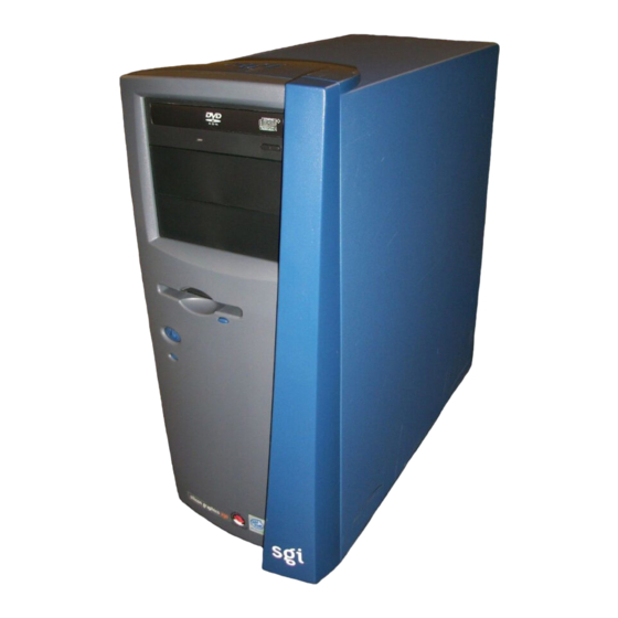
Silicon Graphics 230 Manuals
Manuals and User Guides for Silicon Graphics 230. We have
2
Silicon Graphics 230 manuals available for free PDF download: User Manual, Quick Start Manual
Silicon Graphics 230 User Manual (148 pages)
Visual Workstation
Brand:
Silicon Graphics
| Category:
Desktop
| Size: 5 MB
Table of Contents
Table of Contents
5
Figures
9
Tables
13
About this Guide
15
Obtaining Publications
15
Reader Comments
16
1 System Setup
17
External Structure
18
Figure 1-1 Front Bezel
18
Figure 1-2 Rear Panel
19
Figure 1-3 I/O Ports
20
Internal Structure
21
Figure 1-4 Internal Structure
21
Figure 1-5 5.25-Inch and 3.5-Inch Drive Bays
23
Pre-Installation Instructions
24
Connecting External Devices
25
Figure 1-6 Connecting AC Power Cable
25
Figure 1-7 Connecting Keyboard, Mouse, and Ethernet Cable
26
Figure 1-8 Connecting DB15 HD Video Cable
27
Figure 1-9 Connecting Speakers
29
Figure 1-10 I/O Panel
30
2 Installation of Customer Replaceable Components
31
Pre-Installation Instructions
32
Figure 2-1 Removing Side Panel
32
Figure 2-2 Removing Bezel
33
Removing and Installing Drives
34
Removing and Installing a 5.25-Inch Drive
34
Figure 2-3 Mounting Drive Rails to 5.25-Inch Drives
35
Figure 2-4 Removing Bezel Blanking Plate
36
Figure 2-5 Installing Bezel Blanking Plate
37
Removing and Installing a 3.5-Inch Drive in the Front-Access Drive Cage
38
Figure 2-6 Removing Drive from Drive Bay
38
Figure 2-7 Detaching 3.5-Inch Drive Filler Plate
39
Figure 2-8 Mounting Drive Rails to 3.5-Inch Drives
41
Removing and Installing a 3.5-Inch Drive in the Internal Drive Cage
42
Figure 2-9 Mounting Drives in the Internal Drive Cage
43
Replacing the Power Supply
45
Figure 2-10 Removing Power Supply Inside Screw
46
Figure 2-11 Connecting Power Supply Cables
47
Replacing Fans
48
Replacing Rear System Fan
48
Figure 2-12 Disengaging Release Buttons and Removing Rear Fan
49
Figure 2-13 Connecting Rear Fan Cable
50
Replacing Front System Fan
51
Figure 2-14 Removing Front Fan Screw and Releasing Clips
51
Figure 2-15 Removing Fan from Plastic Frame
52
Figure 2-16 Installing Fan into Plastic Frame
53
Figure 2-17 Connecting Front Fan Cable
54
Replacing Expansion Cards
55
Figure 2-18 Removing Expansion Card
56
Figure 2-19 Location of the Retaining Screw for the Expansion Slot Filler Plate
57
Figure 2-20 Installing Expansion Card
58
Replacing System Board
59
Figure 2-21 Location of System Board Screw
60
Figure 2-22 Removing Retaining Bracket from System Board
61
Figure 2-23 Snapping Retaining Bracket Onto System Board
62
Figure 2-24 Positioning the System Board on Its Standoff Hooks
63
Figure 2-25 Location of System Board Connectors
64
Replacing I/O Panel Gasket
65
Figure 2-26 Removing I/O Panel Gasket
65
Figure 2-27 Installing I/O Panel Gasket
66
Securing the System
67
Figure 2-28 Location of Locking Loop
67
Figure 2-29 Removing Locking Hook from Its Storage Slot
68
Figure 2-30 Installing Locking Loop in Its Functional Slot
69
Post-Installation Instructions
70
Figure 2-31 Replacing Bezel
70
Figure 2-32 Placing Side Panel Onto Lower Chassis Rail
71
Figure 2-33 Sliding Side Panel into Place
72
3 System Board
73
Overview
73
Processor
73
Memory
74
System Chipsets
74
Expansion Slots
75
Hardware Management Support
75
Major Components
76
System Board Layout
77
Figure 3-1 System Board Layout
77
Table 3-1 Connector Descriptions
78
Figure 3-2 CN13 Connector Settings
80
Table 3-2 Multi Connector Details
80
Table 3-3 Frequency Setting
81
System Component Installation
82
ESD Precautions
82
Installing and Removing the CPU
82
Figure 3-3 Installing a CPU
83
Figure 3-4 Attaching Fan/Heatsink to CPU
84
Installing and Removing Memory Modules
85
Figure 3-5 Installing a DIMM
86
Figure 3-6 Removing a DIMM
87
Error Messages
88
Software Error Messages
88
System Error Messages
88
Table 3-4 System Error Messages
88
4 Setup Utility
93
Introduction
93
Entering Setup
93
Figure 4-1 Basic Setup Utility Screen
94
Figure 4-2 Advanced Setup Utility Screen
95
System Information
96
Figure 4-3 System Information Screen
96
Table 4-1 System Information
96
Product Information
98
Figure 4-4 Product Information Screen
98
Table 4-2 Product Information
98
Disk Drives
99
Figure 4-5 Disk Drives Screen
99
IDE Channel Type
100
Table 4-3 Disk Drives Parameters
100
Figure 4-6 IDE Channel Type Screen
101
Table 4-4 IDE Drive Parameters
101
Onboard Peripherals
104
Figure 4-7 Onboard Peripherals Screen
104
Table 4-5 Onboard Peripherals Parameters
105
Power Management
108
Figure 4-8 Power Management Screen
108
Table 4-6 Power Management Parameters
109
Boot Options
111
Figure 4-9 Boot Options Screen
111
Table 4-7 Boot Options Parameters
112
Date and Time
114
Figure 4-10 Date and Time Screen
114
Table 4-8 Date and Time Parameters
114
System Security
115
Supervisor Password
115
Figure 4-11 System Security Screen
115
Figure 4-12 Supervisor Password Screen
116
Figure 4-13 Exit Setup Screen
117
Figure 4-14 Exit Setup Screen
117
User Password
118
Disk Drive Control
118
Figure 4-15 User Password Screen
118
Table 4-9 Disk Drive Control
118
Advanced Options
119
Figure 4-16 Advanced Options Screen
119
Memory/Cache Options
119
Figure 4-17 Memory/Cache Options Screen
120
Table 4-10 Memory/Cache Options Parameters
120
Figure 4-18 Pnp/Pci Configuration
121
Pnp/Pci Options
121
Table 4-11 Pnp/Pci Options Parameters
122
Load Default Settings
124
Figure 4-19 Load Default Settings Screen
124
Abort Settings Change
125
Figure 4-20 Abort Settings Change Screen
125
Exit Setup
126
Figure 4-21 Exit Setup Screen
126
Figure 4-22 Save Settings Screen
126
Connector Pinouts
127
Keyboard Port
128
Figure A-1 Keyboard Port Pinout
128
Table A-1 Keyboard Port Pinout
128
Mouse Port
129
Figure A-2 Mouse Port Pinout
129
Table A-2 Mouse Port Pinout
129
Video-Out Ports
130
DB15 HD Port
130
Figure A-3 DB15 HD Port Pinout
130
Table A-3 DB15 HD Port Pinout
130
Figure A-4 Serial Port Pinout
131
Serial Ports
131
Table A-4 Serial Port Pinout
131
Figure A-5 Parallel Port Pinout
132
Parallel Port
132
Table A-5 Parallel Port Pinout
132
Figure A-6 USB Port Pinout
133
Table A-6 USB Port Pinout
133
USB Ports
133
Ethernet Port
134
Figure A-7 Ethernet Port Pinouts
134
Table A-7 Ethernet Port Pinout
134
Audio Ports
135
Figure A-8 MIC-In Port Pinout
135
Figure A-9 Line Level Port
135
Line-In and Line-Out Ports
135
MIC-In Port
135
Table A-8 MIC-In, Line-In, Line-Out Port Pinouts
135
Physical Environment Specifications
137
Table B-1 Physical Environment Specifications
137
Figure B-1 System Dimensions
138
Regulatory Information
139
FCC Notice
139
Notice: Shield Cables
139
Notice: Peripheral Devices
140
Use Conditions
140
Notice: Canadian Users
140
Remarque à L'intention des Utilisateurs Canadiens
140
Important Safety Instructions
140
Laser Compliance Statement
142
Class 1 Laser Product
142
Appareil a Laser de Classe 1
142
Luokan 1 Laserlaite Laser Klasse 1
143
Producto Láser de la Clase I
143
Varo! Lavattaessa Olet Alttina Lasersåteilylle
143
Lithium Battery Statement
143
Index
145
Advertisement
Silicon Graphics 230 Quick Start Manual (8 pages)
Installing an AGP Card in the Visual Workstations
Brand:
Silicon Graphics
| Category:
Desktop
| Size: 0 MB
Table of Contents
Pre-Installation Instructions
1
AGP Card Installation
2
Post-Installation Instructions
4
Graphics Driver Installation
7
Advertisement
Related Products
Silicon Graphics 2800
Silicon Graphics 2400
Silicon Graphics 750
Silicon Graphics Fuel
Silicon Graphics IRIS 1000
Silicon Graphics IRIS 1200
Silicon Graphics IRIS Indigo
Silicon Graphics IRIS Series
Silicon Graphics IRIS Workstation
Silicon Graphics O2
Silicon Graphics Categories
Server
Desktop
Storage
Monitor
Computer Hardware
More Silicon Graphics Manuals
Login
Sign In
OR
Sign in with Facebook
Sign in with Google
Upload manual
Upload from disk
Upload from URL