
Related Manuals for Juniper M120


Summary of Contents for Juniper M120
- Page 1 M120 Multiservice Edge Router Hardware Guide Modified: 2018-07-08 Copyright © 2018, Juniper Networks, Inc.
- Page 2 END USER LICENSE AGREEMENT The Juniper Networks product that is the subject of this technical documentation consists of (or is intended for use with) Juniper Networks software. Use of such software is subject to the terms and conditions of the End User License Agreement (“EULA”) posted at https://www.juniper.net/support/eula/.
-
Page 3: Table Of Contents
Outstanding Issues with the M120 Router ....... . . 5... - Page 4 M120 Control Board (CB) Description ........
- Page 5 M120 Router Physical Specifications ........
- Page 6 M120 Router Installation Summary ........
- Page 7 Overview of Installing and Replacing Components ....179 M120 Field-Replaceable Units (FRUs) ........179 Tools and Parts Required to Replace M120 Components .
- Page 8 Removing a M120 DIMM Module ........200...
- Page 9 Maintaining M120 PICs and PIC Cables ....... . . 275...
- Page 10 Tools and Parts Required to Remove Components from an M120 Router ..306 Packing the M120 Router for Shipment ....... . 306 Guidelines for Packing M120 Components for Shipment .
- Page 11 Agency Approvals for M120 Routers ........
- Page 12 M120 Multiservice Edge Router Hardware Guide Copyright © 2018, Juniper Networks, Inc.
- Page 13 Figure 4: M120 Midplane ..........10 Figure 5: M120 Cable Management System ....... 11 Figure 6: Front Panel of the M120 Craft Interface .
- Page 14 Connecting the M120 to Ground ........
- Page 15 Figure 56: M120 Routing Engine Alarm Relay Contacts ..... 163 Figure 57: Attaching a Cable to an M120 PIC ......166 Chapter 21 Providing Power to the M120 .
- Page 16 Figure 112: M120 Routing Engine Serial Number Label ..... 300 Figure 113: M120 CB Serial Number Label ....... 300 Figure 114: M120 FPC Serial Number Label .
- Page 17 Table 4: M120 Host Subsystem LEDs ........14 Table 5: FEB LEDs on the M120 Craft Interface ......15 Table 6: M120 FPC LEDs .
- Page 18 Table 43: M120 PIC/FPC Compatibility ........66...
- Page 19 Overview of Installing and Replacing Components ....179 Table 67: M120 Field-Replaceable Units ....... . 180 Table 68: Tools and Parts Required .
- Page 20 M120 Multiservice Edge Router Hardware Guide Copyright © 2018, Juniper Networks, Inc.
-
Page 21: About The Documentation
® To obtain the most current version of all Juniper Networks technical documentation, see the product documentation page on the Juniper Networks website at https://www.juniper.net/documentation/ If the information in the latest release notes differs from the information in the documentation, follow the product Release Notes. -
Page 22: Table 1: Notice Icons
M120 Multiservice Edge Router Hardware Guide Table 1: Notice Icons Icon Meaning Description Informational note Indicates important features or instructions. Caution Indicates a situation that might result in loss of data or hardware damage. Warning Alerts you to the risk of personal injury or death. -
Page 23: Documentation Feedback
We encourage you to provide feedback, comments, and suggestions so that we can improve the documentation. You can provide feedback by using either of the following methods: Online feedback rating system—On any page of the Juniper Networks TechLibrary site , simply click the stars to rate the https://www.juniper.net/documentation/index.html content, and use the pop-up form to provide us with information about your experience. -
Page 24: Requesting Technical Support
7 days a week, 365 days a year. Self-Help Online Tools and Resources For quick and easy problem resolution, Juniper Networks has designed an online self-service portal called the Customer Support Center (CSC) that provides you with the following features: Find CSC offerings: https://www.juniper.net/customers/support/... - Page 25 About the Documentation For international or direct-dial options in countries without toll-free numbers, see https://www.juniper.net/support/requesting-support.html Copyright © 2018, Juniper Networks, Inc.
- Page 26 M120 Multiservice Edge Router Hardware Guide xxvi Copyright © 2018, Juniper Networks, Inc.
-
Page 27: Overview
PART 1 Overview System Overview on page 3 M120 Router Release Notes on page 5 Chassis Components and Descriptions on page 7 Cooling System Components and Descriptions on page 19 Host Subsystem Components and Descriptions on page 21 Line Card Components and Descriptions on page 51... - Page 28 M120 Multiservice Edge Router Hardware Guide Copyright © 2018, Juniper Networks, Inc.
-
Page 29: System Overview
M120 Component Redundancy on page 4 M120 Router Description The M120 Multiservice Edge router is a complete routing system that provides SONET/SDH, ATM, Ethernet, and channelized interfaces for large networks and network applications, such as those supported by Internet service providers (ISPs) and large enterprise customers. -
Page 30: M120 Component Redundancy
M120 Router Chassis Description on page 7 Documentation M120 Host Subsystem Description on page 21 M120 AC Power Supply Description on page 72 M120 DC Power Supply Description on page 72 M120 Cooling System Description on page 19 Copyright © 2018, Juniper Networks, Inc. -
Page 31: M120 Router Release Notes
Errata with the M120 Router Documentation on page 5 Outstanding Issues with the M120 Router This section lists outstanding issues with the M120 Multiservice Edge Router. For information about software issues, see the Junos OS Release Notes. There are currently no outstanding issues for the M120 router documentation. - Page 32 M120 Multiservice Edge Router Hardware Guide Copyright © 2018, Juniper Networks, Inc.
-
Page 33: Chassis Components And Descriptions
M120 Alarm LEDs and Alarm Cutoff/Lamp Test Button on page 13 M120 Component LEDs on the Craft Interface on page 14 M120 External Clock Interface Ports on the Craft Interface on page 16 M120 Alarm Relay Contacts on the Craft Interface on page 17... -
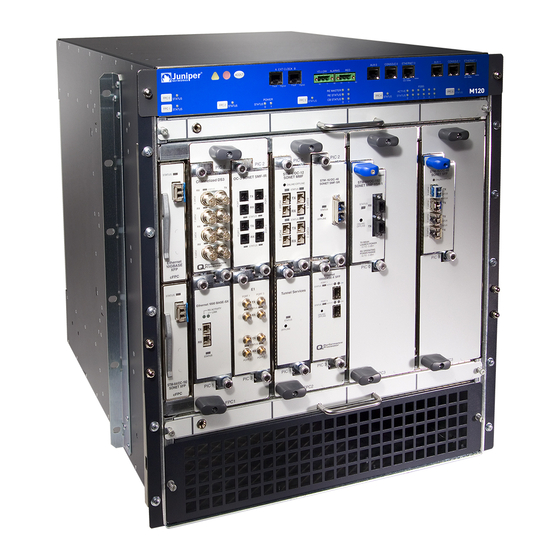
Page 34: Figure 1: Front View Of A Fully Configured M120 Router Chassis
M120 Multiservice Edge Router Hardware Guide Figure 1: Front View of a Fully Configured M120 Router Chassis Figure 2: Rear View of a Fully Configured AC-Powered M120 Router Chassis Copyright © 2018, Juniper Networks, Inc. -
Page 35: M120 Midplane Description
Chapter 3: Chassis Components and Descriptions Figure 3: Rear View of a Fully Configured DC-Powered M120 Router Chassis For chassis serial number information , see “Displaying M120 Router Components and Serial Numbers” on page 297. Related M120 Router Physical Specifications on page 82... -
Page 36: M120 Cable Management System Description
Serial Numbers” on page 297. Related M120 Router Description on page 3 Documentation M120 Router Chassis Description on page 7 M120 Cable Management System Description The cable management system (see Figure 5 on page 11) consists of a row of nine semicircular plastic bobbins mounted on the front of the router below the FPC card cage. -
Page 37: M120 Craft Interface Description
Chapter 3: Chassis Components and Descriptions Figure 5: M120 Cable Management System Related Maintaining M120 PICs and PIC Cables on page 275 Documentation Replacing an M120 PIC Cable on page 228 M120 Craft Interface Description The craft interface allows you to view status and troubleshooting information at a glance and to perform many system control functions. -
Page 38: M120 Alarm Relay Contacts On The Craft Interface
The alarm relay contacts are located below the Routing Engine ports. M120 External Clock Interface Ports on the Craft Interface Two external clock ports... -
Page 39: M120 Alarm Leds And Alarm Cutoff/Lamp Test Button
Replacing Alarm Relay Wires on the M120 Craft Interface on page 183 RJ-45 Connector Pinouts for the External Clock Ports on page 107 RJ-45 Connector Pinouts for the M120 Routing Engine ETHERNET Port on page 106 RJ-45 Connector Pinouts for the Routing Engine AUX and CONSOLE Ports on page 106... -
Page 40: M120 Component Leds On The Craft Interface
M120 Craft Interface Description on page 11 Documentation M120 Routing Engine Interface Ports and Status Indicators on page 28 M120 External Clock Interface Ports on the Craft Interface on page 16 Replacing the M120 Craft Interface on page 184 M120 Component LEDs on the Craft Interface... -
Page 41: Feb Leds On The M120 Craft Interface
, are located on the lower left of the craft interface under the POWER label. Table 7 on page 15 describes the functions of the power supply LEDs. Table 7: Power Supply LEDs on the M120 Craft Interface Label Color State Description... -
Page 42: M120 External Clock Interface Ports On The Craft Interface
The LED on the lower right as you face the craft interface indicates if there is a fault. Table 8 on page 16 describes the external clock port LEDs, Table 8: External Clock LEDs on the M120 Craft Interface Label Color State... -
Page 43: M120 Alarm Relay Contacts On The Craft Interface
RJ-45 Connector Pinouts for the External Clock Ports on page 107 Documentation Connecting the M120 Router to an External Clocking Device on page 163 M120 Alarm Relay Contacts on the Craft Interface The host interface has two alarm relay contacts for connecting the router to external... - Page 44 M120 Multiservice Edge Router Hardware Guide Copyright © 2018, Juniper Networks, Inc.
-
Page 45: Cooling System Components And Descriptions
To function properly, the entire cooling system requires an unobstructed airflow and proper clearance around the site, as described in “M120 Clearance Requirements for Airflow and Hardware Maintenance” on page Copyright © 2018, Juniper Networks, Inc. -
Page 46: Figure 7: Airflow Through The M120 Chassis
Figure 8: M120 Front Fan Tray Figure 9: M120 Rear Fan Tray Related Troubleshooting the M120 Cooling System on page 286 Documentation Maintaining the M120 Air Filter on page 263 Replacing an M120 Air Filter on page 187... -
Page 47: Chapter 5 Host Subsystem Components And Descriptions
M120 RE-A-1800x2 Routing Engine Description on page 25 RE-A-1800 Routing Engine LEDs on page 27 M120 Routing Engine Interface Ports and Status Indicators on page 28 Routing Engine Specifications on page 29 Supported Routing Engines by Router on page 33... -
Page 48: M120 Routing Engine Description
M120 Multiservice Edge Router Hardware Guide M120 Control Board (CB) Description on page 47 M120 Routing Engine Description The Routing Engine runs the Junos OS. The software processes that run on the Routing Engine maintain the routing tables, manage the routing protocols used on the router, control the router interfaces, control some chassis components, and provide the interface for system management and user access to the router. -
Page 49: Routing Engine Components
Each Routing Engine has one 10/100-Mbps Ethernet port for connecting to a management network, and two asynchronous serial ports—one for connecting to a console and one for connecting to a modem or other auxiliary device. EEPROM—Stores the serial number of the Routing Engine. Copyright © 2018, Juniper Networks, Inc. -
Page 50: Routing Engine Boot Sequence
DRAM), issue the show chassis routing-engine command. Figure 12: USB Memory Device in an M120 Routing Engine Routing Engine Boot Sequence The Routing Engine boots from the storage media in this order: the USB device, then the CompactFlash card (if present), then the hard disk (or two solid state drives (SSD) in the case of the RE-A-1800x2, which appear as DISK1 and DISK2), and then the LAN. -
Page 51: M120 Routing Engine Leds
Maintaining the M120 Host Subsystem on page 266 Replacing an M120 Routing Engine on page 195 Routing Engine Interface Cable and Wire Specifications for the M120 Router on page 105 M120 Routing Engine LEDs Each Routing Engine has one LED that indicates its status. The LED, labeled... -
Page 52: Figure 13: Re-A-1800X2 Routing Engine
M120 Multiservice Edge Router Hardware Guide USB port—Provides a removable media interface through which you can install the Junos OS manually. See Figure 14 on page 27. Junos supports USB version 1.0. CompactFlash card—Provides primary storage for software images, configuration files, and microcode. -
Page 53: Routing Engine Boot Sequence
M120 Routing Engine Description on page 22 Documentation M120 Host Subsystem Description on page 21 Taking the M120 Host Subsystem Offline on page 267 Supported Routing Engines by Router on page 33 RE-A-1800 Routing Engine LEDs Each Routing Engine has four LEDs that indicate its status. The LEDs, labeled... -
Page 54: M120 Routing Engine Interface Ports And Status Indicators
LED lights green when traffic is passing through the port. Related RJ-45 Connector Pinouts for the M120 Routing Engine ETHERNET Port on page 106 Documentation RJ-45 Connector Pinouts for the Routing Engine AUX and CONSOLE Ports on page 106 RJ-45 Connector Pinouts for the External Clock Ports on page 107 Copyright ©... -
Page 55: Routing Engine Specifications
Ethernet disk CompactFlash card R E - S - 2 0 0 0 - 4 0 9 6 2.0-GHz 4096 MB Gigabit 40 GB hard 1 GB SCB, SCBE Pentium Ethernet disk CompactFlash card Copyright © 2018, Juniper Networks, Inc. - Page 56 M120 Multiservice Edge Router Hardware Guide Table 11: Routing Engine Specifications (continued) Routing Connection First Junos OS Switch Control Engine Processor Memory to PFEs Disk Media Support Board RE-C1800 1.8-GHz 8 GB Gigabit 4 GB T1600 router in a CB-T for a...
- Page 57 SSDs RE-S-X6-128G 2.1 Ghz 128 GB Gigabit 18.1R1 Ethernet 100-GB SSDs R E M X 2 K - X 8 - 1 2 8 G 2.1 Ghz 128 GB Gigabit 18.1R1 Ethernet 100-GB SSDs Copyright © 2018, Juniper Networks, Inc.
-
Page 58: Table 12: End-Of-Life Routing Engine Specifications
M120 Multiservice Edge Router Hardware Guide NOTE: Use shielded CAT5e cable for connecting the , and CONSOLE ports in RE-S-X6-64G, REMX2K-X8-64G, and REMX2008-X8-64G MGMT Routing Engines. Table 12: End-of-Life Routing Engine Specifications Routing Connection First Junos OS Engine Processor Memory... -
Page 59: Supported Routing Engines By Router
M7i Routing Engines on page 34 M10i Routing Engines on page 34 M40e Routing Engines on page 34 M120 Routing Engines on page 35 M320 Routing Engines on page 35 MX5, MX10, MX40, and MX80 Routing Engine on page 36... -
Page 60: M7I Routing Engines
M120 Multiservice Edge Router Hardware Guide M7i Routing Engines Table 13 on page 34 lists the Routing Engines supported by the M7i router. The M7i router supports 32-bit Junos OS only. Table 13: M7i Routing Engines Name in CLI First Supported 32-bit... -
Page 61: M120 Routing Engines
RE-A-1000-2048 RE-A-1000 fxp0 fxp1 fxp2 M120 Routing Engines Table 16 on page 35 lists the Routing Engines supported by the M120 router. Table 16: M120 Routing Engines First First Supported Supported Management Name in CLI 32-bit Junos OS 64-bit Junos... -
Page 62: Mx5, Mx10, Mx40, And Mx80 Routing Engine
M120 Multiservice Edge Router Hardware Guide Table 17: M320 Routing Engines First First Supported Supported Management Name in CLI 32-bit Junos OS 64-bit Junos Ethernet Internal Ethernet Model Number Output Release OS Release Interface Interface RE-1600-2048 (EOL – fxp0 fxp1 RE-4.0... -
Page 63: Mx240 Routing Engines
10.4 fxp0 RE-S-1800X4 12.1R3 RE-S-1800X4-16G RE-S-1800x4 11.4R5 10.4 fxp0 12.1R3 RE-S-1800X4-32G-S 12.3R4 12.3R4 fxp0 em0, RE-S-1800X4 13.2R1 13.2R1 RE-S-X6-64G – 15.1F4 fxp0 ixlv0, igb0 RE-S-2X00x6 16.1R1 RE-S-X6-64G-LT – 18.1R1 fxp0 ixlv0, igb0 RE-S-2X00x6 -LT Copyright © 2018, Juniper Networks, Inc. -
Page 64: Mx480 Routing Engines
M120 Multiservice Edge Router Hardware Guide Table 20: MX240 Supported Routing Engines (continued) RE-S-X6-128G – 18.1R1 fxp0 ixlv0, igb0 RE-S-2X00x6-128 MX480 Routing Engines Table 21 on page 38 lists the Routing Engines supported by MX480 routers. Table 21: MX480 Supported Routing Engines... -
Page 65: Mx960 Routing Engines
RE-S-2X00x6 16.1R1 RE-S-X6-64G (For – 17.1R1 fxp0 ixlv0, igb0 RE-S-2X00x6 MX960-VC) RE-S-X6-128G RE-S-2X00x6-128 – 18.1R1 fxp0 ixlv0, igb0 MX2008 Routing Engines Table 23 on page 40 lists the Routing Engines supported by MX2008 routers. Copyright © 2018, Juniper Networks, Inc. -
Page 66: Mx2010 Routing Engines
M120 Multiservice Edge Router Hardware Guide Table 23: MX2008 Supported Routing Engines Management Internal Name in CLI First Supported 64-bit Junos Ethernet Ethernet Model Number Output OS Release Interface Interface REMX2008-X8-64G RE-MX2008-X8-64G 15.1F7 fxp0 ixlv0 ixlv1 REMX2008-X8-64G-LT 17.2R1 fxp0 ixlv0... -
Page 67: Mx10003 Routing Engines
The PTX1000 supports 64-bit Junos OS only. Table 27: PTX1000 Routing Engines Name in CLI First Supported Junos OS Management Internal Ethernet Model Number Output Release Ethernet Interface Interface Built-in Routing 16.1X65-D30 bme0 RE-PTX1000 Engine 17.2R1 Copyright © 2018, Juniper Networks, Inc. -
Page 68: Ptx3000 Routing Engines
M120 Multiservice Edge Router Hardware Guide PTX3000 Routing Engines Table 28 on page 42 lists the Routing Engines supported on the PTX3000. NOTE: The PTX3000 supports 64-bit Junos OS only. Table 28: PTX3000 Routing Engines Name in CLI First Supported Junos OS... -
Page 69: Ptx10008 And Ptx10016 Routing Engines
Routing Engines supported by the T320 router. Table 31: T320 Routing Engines First Supported 32-bit Junos OS Management Internal Ethernet Model Number Name in CLI Output Release Ethernet Interface Interface RE-600-2048 (EOL details: fxp0 fxp1 RE-3.0 RE-3.0 TSB14373 (RE-600) fxp2 Copyright © 2018, Juniper Networks, Inc. -
Page 70: T640 Routing Engines
M120 Multiservice Edge Router Hardware Guide Table 31: T320 Routing Engines (continued) First Supported 32-bit Junos OS Management Internal Ethernet Model Number Name in CLI Output Release Ethernet Interface Interface RE-1600-2048 (EOL details: RE-4.0 fxp0 fxp1 TSB14374 fxp2 RE-A-2000-4096 fxp0... -
Page 71: T1600 Routing Engines
T1600 router in a 11.4R2 routing matrix: 11.4R2 T4000 Routing Engines Table 34 on page 46 lists the Routing Engines supported by the T4000 router. NOTE: The T4000 router supports 64-bit Junos OS only. Copyright © 2018, Juniper Networks, Inc. -
Page 72: Tx Matrix Routing Engines
M120 Multiservice Edge Router Hardware Guide Table 34: T4000 Routing Engines Management Name in CLI First Supported 64-bit Junos OS Ethernet Internal Ethernet Model Number Output Release Interface Interface RE-DUO-C1800-8G RE-DUO-1800 Standalone T4000 router: 12.1 bcm0 T4000 router in a routing matrix: 13.1 RE-DUO-C1800-16G Standalone T4000 router: 12.1R2... -
Page 73: Tx Matrix Plus (With 3D Sibs) Routing Engines
Routing Engine Specifications on page 29 Documentation Understanding Internal Ethernet Interfaces Understanding Management Ethernet Interfaces M120 Control Board (CB) Description Each CB works with an installed Routing Engine to provide control and monitoring functions for the router (see Figure 15 on page 48). -
Page 74: Cb Components
Power circuits for the Routing Engine and CB. Offline button—Takes the CB offline when pressed. Related M120 Control Board (CB) LEDs on page 48 Documentation Maintaining the M120 Host Subsystem on page 266 Replacing an M120 CB on page 202... -
Page 75: Table 38: M120 Control Board Leds
FAIL Blue On steadily Control board is master. MSTR Related M120 Control Board (CB) Description on page 47 Documentation Maintaining the M120 Host Subsystem on page 266 Replacing an M120 CB on page 202 Copyright © 2018, Juniper Networks, Inc. - Page 76 M120 Multiservice Edge Router Hardware Guide Copyright © 2018, Juniper Networks, Inc.
-
Page 77: Line Card Components And Descriptions
CHAPTER 6 Line Card Components and Descriptions M120 Flexible PIC Concentrators (FPCs) Description on page 51 M120 Flexible PIC Concentrators (FPCs) LED on page 54 M120 Compact FPCs (CFPCs) Description on page 54 M120 FPCs and CFPCs Supported on page 56... -
Page 78: Figure 16: Fpc And Cfpcs Installed In An M120 Router Chassis
FPC, are enabled. Forwarding on other FPC slots continues uninterrupted during this process. Figure 16: FPC and CFPCs Installed in an M120 Router Chassis Faceplates on FPCs for the M120 router are labeled with the FPC type ( , or FPC1... -
Page 79: Fpc Components
Chapter 6: Line Card Components and Descriptions Figure 17: FPC1, FPC2, and FPC3 for the M120 Router FPC Components on page 53 FPC Terminology on page 53 FPC Components Each FPC consists of the following components: FPC card carrier, which includes the PIC slots. -
Page 80: M120 Flexible Pic Concentrators (Fpcs) Led
. For more information about the FPC LEDs FPC0 FPC5 located on the craft interface, see “FPC LEDs on the M120 Craft Interface” on page Related M120 FPCs and CFPCs Supported on page 56 Documentation Maintaining M120 FPCs and CFPCs on page 270... -
Page 81: Figure 18: Fpc And Cfpcs Installed In An M120 Router Chassis
Figure 18: FPC and CFPCs Installed in an M120 Router Chassis Two CFPCs are available for the M120 router: a 10-Gigabit Ethernet CFPC and an OC192 CFPC. Each CFPC is rated at 10 Gbps full duplex. Both CFPCs provide receptacles for XFP optical transceivers. -
Page 82: Cfpc Components
M120 FPCs and CFPCs Supported M120 routers support the FPCs listed in Table 39 on page You can install any combination of these FPCs in the M120 router. Table 39: FPCs Supported by the M120 Router Maximum Number of PICs Supported... -
Page 83: M120 Pics Description
A CFPC is a combination of a PIC and an FPC. It contains the interface circuitry and the FPC as a single assembly. The CFPCs provide receptacles for XFP optical transceivers. The M120 chassis provides two slots for CFPCs, and supports any combination of CFPC types. M120 routers support the CFPCs listed in... -
Page 84: M120 Pic Leds
Replacing an M120 PIC on page 223 M120 PIC LEDs Each PIC has LEDs located on the faceplate. For more information about LEDs on the PIC faceplate, see the “LEDs” section for each PIC in the M120 Multiservice Edge Router Interface Module Reference. Related... - Page 85 Chapter 6: Line Card Components and Descriptions Table 41: PICs Supported in the M120 Router (continued) First Junos OS PIC Family and Type Ports Model Number Release Support ATM2 OC3/STM1 IQ PIC (M120 Router) PB-2OC3-ATM2-MM 8.0R2 PB-2OC3-ATM2-SMIR ATM2 OC12/STM4 IQ PICs (M120 Router) PB-1OC12-ATM2-MM 8.0R2...
- Page 86 M120 Multiservice Edge Router Hardware Guide Table 41: PICs Supported in the M120 Router (continued) First Junos OS PIC Family and Type Ports Model Number Release Support Channelized OC3/STM1 Enhanced IQ (IQE) PIC with PB-2CHOC3-STM1-IQE-SFP SFP (M120 Router) Channelized OC12/STM4 Enhanced IQ (IQE) PIC...
- Page 87 Chapter 6: Line Card Components and Descriptions Table 41: PICs Supported in the M120 Router (continued) First Junos OS PIC Family and Type Ports Model Number Release Support Gigabit Ethernet IQ EOL PICs with SFP (M120 PB-1GE-SFP-QPP 8.0R2 Router) PB-2GE-SFP-QPP...
- Page 88 M120 Multiservice Edge Router Hardware Guide Table 41: PICs Supported in the M120 Router (continued) First Junos OS PIC Family and Type Ports Model Number Release Support Adaptive Services II EOL PIC (M120 Router) – PB-AS2 8.0R2 Adaptive Services II Layer 2 Services EOL PIC (M120 –...
-
Page 89: M120 End-Of-Life Pics Supported
M120 PIC/FPC Compatibility on page 66 M120 End-of-Life PICs Supported Table 42 on page 63 lists the end-of-life PICs supported in the M120 router. The PICs are listed alphabetically by PIC family. NOTE: The M120 router is now end-of-life. See the JTAC support bulletin TSB16809 for additional information about the PICs and other associated FRUs that moved to end-of-life with the router. - Page 90 M120 Multiservice Edge Router Hardware Guide Table 42: End-of-Life PICs Supported in the M120 Router (continued) First Junos OS PIC Family and Type Ports Model Number Release Support Channelized STM1 IQ EOL PIC (M120 Router) PB-1CHSTM1-SMIR-QPP 8.0R2 Channelized OC3 IQ EOL PIC (M120 Router) PB-1CHOC3-SMIR-QPP 8.0R2...
- Page 91 Chapter 6: Line Card Components and Descriptions Table 42: End-of-Life PICs Supported in the M120 Router (continued) First Junos OS PIC Family and Type Ports Model Number Release Support 10-Gigabit Ethernet IQ2 EOL PIC with XFP (M120 PC-1XGE-TYPE3-XFP-IQ2 Router) Services Adaptive Services II EOL PIC (M120 Router) –...
-
Page 92: M120 Pic/Fpc Compatibility
PIC/FPC compatibility matrix that indicates the first Junos OS Release in which an FPC supports each PIC currently supported for the M120 router. For example, Junos OS Release 8.0R2 is the first release in which the FPC1 supports the ATM2 DS3 IQ PIC. - Page 93 Chapter 6: Line Card Components and Descriptions Table 43: M120 PIC/FPC Compatibility (continued) Number of PIC Type Ports PIC Model Number FPC1 FPC2 FPC3 ChSTM1 IQ PB-1CHSTM1-SMIR-QPP 8.0R2 – – ChT1 IQ PB-10CHT1-RJ48-QPP 8.0R2 – – Channelized Enhanced IQ (IQE) PICs...
- Page 94 M120 Multiservice Edge Router Hardware Guide Table 43: M120 PIC/FPC Compatibility (continued) Number of PIC Type Ports PIC Model Number FPC1 FPC2 FPC3 Fast Ethernet PB-48FE-TX – 8.0R2 – Gigabit Ethernet PICs Gigabit Ethernet, SFP PB-1GE-SFP 8.0R2 – – Gigabit Ethernet, SFP PB-2GE-SFP –...
- Page 95 Chapter 6: Line Card Components and Descriptions Table 43: M120 PIC/FPC Compatibility (continued) Number of PIC Type Ports PIC Model Number FPC1 FPC2 FPC3 Services PICs Adaptive Services II (AS) EOL PB-AS2 8.0R2 Adaptive Services II (AS) Layer 2 PB-AS2-LAYER2SERVICES 8.0R2...
- Page 96 M120 Multiservice Edge Router Hardware Guide Table 43: M120 PIC/FPC Compatibility (continued) Number of PIC Type Ports PIC Model Number FPC1 FPC2 FPC3 OC12/STM4 (Multi-Rate), SFP PB-4OC3-4OC12-SON-SFP – – OC48c/STM16, SFP PC-4OC48-SON-SFP – – 8.0R2 OC48c/STM16 SFP EOL PB-1OC48-SON-SFP 8.0R2...
-
Page 97: Power System Components And Descriptions
M120 Power Supply LEDs on page 73 M120 Power Supplies Description The M120 router is configurable with either one or two AC or DC power supplies. The power supplies connect to the midplane, which distributes the different output voltages produced by the power supplies to the router components, depending on their voltage requirements. -
Page 98: M120 Dc Power Supply Description
M120 Power Supply LEDs on page 73 Documentation M120 Router Power Requirements on page 88 Connecting Power to a DC-Powered M120 Router on page 169 Maintaining the M120 Power Supplies on page 277 Replacing an M120 DC Power Supply on page 245... -
Page 99: M120 Power Supply Leds
Maintaining the M120 Power Supplies on page 277 Replacing an M120 AC Power Supply on page 239 M120 AC Power, Connection, and Power Cord Specifications on page 93 M120 Power Supply LEDs The LED on each power supply faceplate indicates the status of the power supply (see Table 44 on page 74, which applies to the AC and DC power supply). -
Page 100: Table 44: M120 Power Supply Led
Power supply is functioning normally. Related M120 Router Power Requirements on page 88 Documentation Connecting Power to an AC-Powered M120 Router on page 167 Connecting Power to a DC-Powered M120 Router on page 169 Copyright © 2018, Juniper Networks, Inc. -
Page 101: Switch Fabric Components And Descriptions
M120 Forwarding Engine Boards (FEBs) LEDs on page 77 M120 Forwarding Engine Boards (FEBs) Description The M120 router provides redundant Forwarding Engine Boards (FEBs). The FPC (the board that hosts the PICs) is separate from the FEB (the board that handles the packets). -
Page 102: Feb Components
A crossbar switch that provides connection between the FEB WAN links and the FPC WAN links. Three LEDs located on the FEB faceplate that display the status of the FEB. “M120 Forwarding Engine Boards (FEBs) LEDs” on page 77 describes the functions of the FEB LEDs. -
Page 103: M120 Forwarding Engine Boards (Febs) Leds
ACTIVE a FEB is designated as a backup and has not been failed over to. Related M120 Forwarding Engine Boards (FEBs) Description on page 75 Documentation Replacing an M120 FEB on page 255 Troubleshooting M120 FEBs on page 289 Maintaining the M120 FEBs on page 278... - Page 104 M120 Multiservice Edge Router Hardware Guide Copyright © 2018, Juniper Networks, Inc.
-
Page 105: Site Planning, Preparation, And Specifications
AC Power Requirements and Specifications on page 93 DC Power Requirements and Specifications on page 97 Network Cable and Transceiver Planning on page 101 Management Cable and Transceiver Specifications and Pinouts on page 105 Copyright © 2018, Juniper Networks, Inc. - Page 106 M120 Multiservice Edge Router Hardware Guide Copyright © 2018, Juniper Networks, Inc.
-
Page 107: Preparation Overview
M120 Cabinet Size and Clearance Requirements on page 82 M120 Cabinet Airflow Requirements on page 83 M120 Rack Mounting Requirements on page 83 M120 Clearance Requirements for Airflow and Hardware Maintenance on page 85 M120 Router Environmental Specifications on page 86 M120 Chassis Grounding Specifications on page 87... -
Page 108: M120 Router Physical Specifications
M120 Router Chassis Description on page 7 Documentation M120 Router Physical Specifications on page 82 General Safety Warnings for Juniper Networks Devices on page 314 Installation Safety Warnings for Juniper Networks Devices on page 322 M120 Chassis Lifting Guidelines on page 321... -
Page 109: M120 Cabinet Airflow Requirements
Route and dress all cables to minimize the blockage of airflow to and from the chassis. Related M120 Cabinet Size and Clearance Requirements on page 82 Documentation Installing the Mounting Hardware for a Front-Mount Four-Post Rack or Cabinet on... -
Page 110: Table 48: M120 Rack Requirements And Specifications
Cabinets, Racks, Panels, and Associated Equipment (document number EIA-310-D) published by the Electronics Components Industry Association. You can stack four M120 routers in a rack that has at least 48 U (84 in. or 2.1 m) of usable vertical space. -
Page 111: M120 Clearance Requirements For Airflow And Hardware Maintenance
Installing the Mounting Hardware for a Front-Mount Open-Frame Rack on page 121 Installation Safety Warnings for Juniper Networks Devices on page 322 Installing the M120 Router Without Using a Mechanical Lift on page 139 M120 Clearance Requirements for Airflow and Hardware Maintenance... -
Page 112: M120 Router Environmental Specifications
Installing the Mounting Hardware for a Front-Mount Open-Frame Rack on page 121 Installation Safety Warnings for Juniper Networks Devices on page 322 Installing the M120 Router Without Using a Mechanical Lift on page 139 M120 Router Environmental Specifications Table 49 on page 86 specifies the environmental specifications required for normal router operation. -
Page 113: M120 Chassis Grounding Specifications
Chapter 9: Preparation Overview Table 49: M120 Router Environmental Specifications (continued) Description Value Temperature Normal operation ensured in temperature range of 32°F (0°C) to 104°F (40°C) Nonoperating storage temperature in shipping container: –40°F (–40°C) to 158°F (70°C) Seismic Designed to meet Telcordia Technologies Zone 4 earthquake... -
Page 114: M120 Router Power Requirements
Table 53 on page 89 lists the power requirements for various hardware components when the router is operating under typical voltage conditions. For PIC power requirements, see the M120 Multiservice Edge Router Interface Module Reference. Table 50: Power System Electrical Specifications... -
Page 115: Table 51: Ac Power Supply Electrical Specifications
60 A @ –48 VDC Internal Supplementary 60 A Protector Table 53: Component Power Requirements DC Current DC Power Requirement Requirement (Amps @ Component (Watts) –48 VDC) Cooling system (normal speed) 187 W 3.90 A Copyright © 2018, Juniper Networks, Inc. - Page 116 DC-powered router. These examples use generalized values for PICs. For PIC power requirements, see the M120 Multiservice Edge Router Interface Module Reference.
- Page 117 Related M120 Power Supplies Description on page 71 Documentation Replacing an M120 AC Power Supply on page 239 Replacing an M120 DC Power Supply on page 245 M120 Router Chassis Description on page 7 Copyright © 2018, Juniper Networks, Inc.
- Page 118 M120 Multiservice Edge Router Hardware Guide Copyright © 2018, Juniper Networks, Inc.
-
Page 119: Ac Power Requirements And Specifications
CHAPTER 10 AC Power Requirements and Specifications M120 AC Power, Connection, and Power Cord Specifications on page 93 Electrical Specifications for the M120 AC Power Supply on page 95 M120 AC Power, Connection, and Power Cord Specifications In the AC power configuration, the router can have up to two load-sharing AC power... -
Page 120: Table 54: Ac Power Cord Specifications
M120 Multiservice Edge Router Hardware Guide WARNING: Translation from Japanese: The attached power cable is only for this product. Do not use the cable for another product. NOTE: In North America, AC power cords must not exceed 4.5 m (approximately 14.75 ft) in length, to comply with National Electrical Code (NEC) Sections 400-8 (NFPA 75, 5-2.2) and 210-52, and Canadian Electrical... -
Page 121: Electrical Specifications For The M120 Ac Power Supply
M120 AC Power Supply Description on page 72 Documentation Replacing an M120 AC Power Supply on page 239 Replacing an M120 AC Power Supply Cord on page 244 Connecting Power to an AC-Powered M120 Router on page 167 Electrical Specifications for the M120 AC Power Supply Table 55 on page 96 lists the AC power supply electrical specifications. -
Page 122: Table 55: Ac Power Supply Electrical Specifications
28 A @ 100 VAC (15 A top inlet, 13 A bottom inlet) 14 A @ 240 VAC Related M120 AC Power Supply Description on page 72 Documentation M120 Power Supply LEDs on page 73 Replacing an M120 AC Power Supply on page 239 Copyright © 2018, Juniper Networks, Inc. -
Page 123: Dc Power Requirements And Specifications
Specifications M120 DC Power, Connection, and Cable Specifications on page 97 Electrical Specifications for the M120 DC Power Supply on page 100 M120 DC Power, Connection, and Cable Specifications In the DC power configuration, the router contains two DC power supplies (see... -
Page 124: Figure 27: Typical Dc Source Cabling To The M120 Router
Figure 27 on page 98 shows a typical DC source cabling arrangement. Figure 27: Typical DC Source Cabling to the M120 Router WARNING: Power plant ground and chassis ground must be connected to the same building ground. -
Page 125: Dc Power Requirements And Specifications
For instructions on replacing a DC power cable, see “Replacing an M120 DC Power Supply Cable” on page 251. Related Connecting Power to a DC-Powered M120 Router on page 169 Documentation Replacing an M120 DC Power Supply on page 245 Copyright © 2018, Juniper Networks, Inc. -
Page 126: Electrical Specifications For The M120 Dc Power Supply
M120 DC Power Supply Description on page 72 Documentation M120 Power Supply LEDs on page 73 Replacing an M120 DC Power Supply on page 245 DC Power Electrical Safety Guidelines for the M120 Router on page 347 Copyright © 2018, Juniper Networks, Inc. -
Page 127: Network Cable And Transceiver Planning
Attenuation is caused by passive media components, such as cables, cable splices, and connectors. Although attenuation is significantly lower for optical fiber than for other media, it still occurs in both multimode Copyright © 2018, Juniper Networks, Inc. -
Page 128: Calculating Power Budget And Power Margin For Fiber-Optic Cables
You can use the to find information about Hardware Compatibility Tool the pluggable transceivers supported on your Juniper Networks device. To calculate the power budget and power margin, perform the following tasks: Calculating Power Budget for Fiber-Optic Cable on page 102... -
Page 129: Calculating Power Margin For Fiber-Optic Cable
(0.5 dB per connector, or 2.5 dB) and two splices (0.5 dB per splice, or 1 dB) as well as higher-order mode losses (0.5 dB). The power margin (P ) is calculated as follows: Copyright © 2018, Juniper Networks, Inc. - Page 130 M120 Multiservice Edge Router Hardware Guide – LL = 13 dB – 2 km (1 dB/km) – 5 (0.5 dB) – 2 (0.5 dB) – 0.5 dB = 13 dB – 2 dB – 2.5 dB – 1 dB – 0.5 dB...
-
Page 131: Management Cable And Transceiver Specifications And Pinouts
Management Cable and Transceiver Specifications and Pinouts Routing Engine Interface Cable and Wire Specifications for the M120 Router on page 105 RJ-45 Connector Pinouts for the M120 Routing Engine ETHERNET Port on page 106 RJ-45 Connector Pinouts for the Routing Engine AUX and CONSOLE Ports on page 106... -
Page 132: Rj-45 Connector Pinouts For The M120 Routing Engine Ethernet Port
M120 Multiservice Edge Router Hardware Guide RJ-45 Connector Pinouts for the M120 Routing Engine ETHERNET Port The port on the craft interface labeled is an autosensing 10/100-Mbps Ethernet ETHERNET RJ-45 receptacle that accepts an Ethernet cable for connecting the Routing Engine to a management LAN (or other device that supports out-of-band management). -
Page 133: Rj-45 Connector Pinouts For The External Clock Ports
DSR/DCD Data Set Ready Clear to Send Related Replacing the Console or Auxiliary Cable on the M120 Routing Engine on page 207 Documentation Maintaining M120 PICs and PIC Cables on page 275 Installing an M120 PIC Cable on page 229... - Page 134 M120 Multiservice Edge Router Hardware Guide Related M120 External Clock Interface Ports on the Craft Interface on page 16 Documentation Maintaining M120 PICs and PIC Cables on page 275 Installing an M120 PIC Cable on page 229 M120 PICs Description on page 57...
-
Page 135: Initial Installation And Configuration
Unpacking the M120 on page 113 Installing the Mounting Hardware on page 119 Installing the M120 With a Mechanical Lift on page 125 Installing the M120 Without a Mechanical Lift on page 129 Connecting the M120 to Ground on page 151... - Page 136 M120 Multiservice Edge Router Hardware Guide Copyright © 2018, Juniper Networks, Inc.
-
Page 137: Installation Overview
Install the router. Installing the M120 Router Using a Mechanical Lift on page 125 Installing the M120 Router Without Using a Mechanical Lift on page 139 Connect cables to the network and external devices. “Connecting the M120 Router to Management and Alarm Devices” on page 153. - Page 138 M120 Multiservice Edge Router Hardware Guide Connect the AC power cord or DC power cables: Connecting Power to an AC-Powered M120 Router on page 167 Connecting Power to a DC-Powered M120 Router on page 169 Power on the router. “Powering On the M120 Router” on page 170.
-
Page 139: Unpacking The M120
CHAPTER 15 Unpacking the M120 Tools and Parts Required to Unpack the M120 Router on page 113 Unpacking the M120 Router on page 113 Verifying M120 Parts Received on page 115 Tools and Parts Required to Unpack the M120 Router... - Page 140 To proceed with the installation, see “Installing the M120 Router Using a Mechanical Lift” on page 125or “Installing the M120 Router Without Using a Mechanical Lift” on page 139. Copyright © 2018, Juniper Networks, Inc.
-
Page 141: Verifying M120 Parts Received
115, and an accessory box, which contains the parts listed in Table 64 on page 116. The parts shipped with your router can vary. Table 63: Parts List for a Fully Configured M120 Router Component Quantity Chassis, including midplane, craft interface... -
Page 142: Table 64: Accessory Box Parts List
M120 Multiservice Edge Router Hardware Guide Table 63: Parts List for a Fully Configured M120 Router (continued) Component Quantity PICs Up to sixteen Type 1 PICs Up to sixteen Type 2 PICs Up to four Type 3 PICs FEBs Up to 6... - Page 143 Ethernet cable, RJ-45/RJ-45, 4-pair stranded UTP, Category 5E, 15' ESD wrist strap with cable Related M120 Router Chassis Description on page 7 Documentation M120 Router Installation Summary on page 111 M120 Site Preparation Checklist on page 81 Copyright © 2018, Juniper Networks, Inc.
- Page 144 M120 Multiservice Edge Router Hardware Guide Copyright © 2018, Juniper Networks, Inc.
-
Page 145: Installing The Mounting Hardware
The hole distances are relative to one of the standard U divisions on the rack. The bottom of all mounting shelves is at 0.04 in. (0.02 U) above a U division. Table 65: Four-Post Rack or Cabinet Mounting Hole Locations for the M120 Router Large... - Page 146 M120 Multiservice Edge Router Hardware Guide On the front rack rails, install cage nuts in the holes specified in Table 65 on page 119 for the large shelf and the spacer bars. On the front of each front rack rail, partially insert a mounting screw into the hole containing the lowest cage nut.
-
Page 147: Installing The Mounting Hardware For A Front-Mount Open-Frame Rack
Chapter 16: Installing the Mounting Hardware Figure 29: Installing the M120 Mounting Hardware for a Four-Post Rack or Cabinet Related M120 Rack Mounting Requirements on page 83 Documentation M120 Site Preparation Checklist on page 81 Installation Safety Warnings for Juniper Networks Devices on page 322... - Page 148 M120 Multiservice Edge Router Hardware Guide Table 66: Open-Frame Rack Mounting Hole Locations for the M120 Router (continued) Hole Distance Above U Division Large Shelf 15.51 in. (39.4 cm) 8.86 U 13.76 in. (34.9 cm) 7.86 U 12.01 in. (30.5 cm) 6.86 U...
-
Page 149: Installing The Mounting Hardware For A Center-Mount Open-Frame Rack
Chapter 16: Installing the Mounting Hardware Figure 30: Installing the M120 Mounting Hardware for an Open-Frame Rack Open-frame rack Large mounting shelf Related M120 Rack Mounting Requirements on page 83 Documentation M120 Site Preparation Checklist on page 81 Installation Safety Warnings for Juniper Networks Devices on page 322... - Page 150 Partially insert screws into the open holes in the ears of the large shelf. Tighten all the screws completely. Related M120 Rack Mounting Requirements on page 83 Documentation M120 Site Preparation Checklist on page 81 Installation Safety Warnings for Juniper Networks Devices on page 322 Copyright © 2018, Juniper Networks, Inc.
-
Page 151: Installing The M120 With A Mechanical Lift
CHAPTER 17 Installing the M120 With a Mechanical Lift Tools Required to Install the M120 Router Using a Mechanical Lift on page 125 Installing the M120 Router Using a Mechanical Lift on page 125 Tools Required to Install the M120 Router Using a Mechanical Lift... - Page 152 For details, see “M120 Clearance Requirements for Airflow and Hardware Maintenance” on page Load the router onto the lift, making sure it rests securely on the lift platform.
-
Page 153: Figure 31: Installing The M120 Router In The Rack
Chapter 17: Installing the M120 With a Mechanical Lift installing the router in an open-frame rack, install a mounting screw into each of the open mounting holes aligned with the rack, starting from the bottom. Visually inspect the alignment of the router. If the router is installed properly in the rack, all the mounting screws on one side of the rack should be aligned with the mounting screws on the opposite side and the router should be level. - Page 154 M120 Multiservice Edge Router Hardware Guide Copyright © 2018, Juniper Networks, Inc.
-
Page 155: Installing The M120 Without A Mechanical Lift
Reinstalling Components in the Chassis After Installing the M120 Router Without a Mechanical Lift on page 142 Tools and Parts Required to Install the M120 Router Without a Mechanical Lift To install the router, you need the following tools and parts: Phillips (+) screwdrivers, numbers 1 and 2 3/8-in. -
Page 156: Removing The Power Supplies
M120 Multiservice Edge Router Hardware Guide cables to the router. Remove components from the chassis, first from the rear and then from the front. Removing the Power Supplies on page 130 Removing FEBs on page 131 Removing CBs on page 132... -
Page 157: Removing Febs
Chapter 18: Installing the M120 Without a Mechanical Lift Figure 32: Removing a Power Supply Before Installing the M120 Router CB 0 FEB 0 FEB 1 FEB 2 FEB 3 FEB 4 FEB 5 PEM 0 PEM 1 Removing FEBs Six FEBs are installed in the router. -
Page 158: Removing Cbs
Repeat the procedure for each of the remaining FEBs. Figure 33: Removing a FEB Before Installing the M120 Router Removing CBs The router can have one or two CBs. They are located in the right rear of the chassis in the slots marked . -
Page 159: Removing A Fan Tray
Repeat the procedure for the second CB. Figure 34: Removing a CB Before Installing the M120 Router Removing a Fan Tray In the front of the chassis, the upper fan tray is located above the FPC card cage, and the lower fan tray is located below the FPC card cage. -
Page 160: Figure 35: Removing An Upper Front Fan Tray Before Installing The M120
When the fans stop spinning, place one hand under the fan tray to support it and pull the fan tray completely out of the chassis. Figure 35: Removing an Upper Front Fan Tray Before Installing the M120 Router Copyright © 2018, Juniper Networks, Inc. -
Page 161: Removing The Cable Management System
Chapter 18: Installing the M120 Without a Mechanical Lift Figure 36: Removing a Lower Rear Fan Tray Before Installing the M120 Router Removing the Cable Management System The cable management system is located below the FPC card cage. The cable management system weighs approximately 5 lb (2.3 kg). -
Page 162: Removing Fpcs
M120 Multiservice Edge Router Hardware Guide Figure 37: Removing the Cable Management System Before Installing the M120 Router Removing FPCs The router holds up to four FPCs, which are installed vertically in the front of the router. An empty FPC weighs 9.0 lb (4.0 kg). A fully configured FPC can weigh up to 12.3 lb (5.6 kg). -
Page 163: Removing A Cfpc
Repeat the procedure for each remaining FPC. Figure 38: Removing an FPC Before Installing the M120 Router Removing a CFPC The router holds up to two CFPCs, which are installed vertically in the front of the router. -
Page 164: Figure 39: Removing A Cfpc Before Installing The M120 Router
They cannot support its weight. Place each individual CFPC in an individual electrostatic bag or on its own antistatic mat on a flat, stable surface. Figure 39: Removing a CFPC Before Installing the M120 Router Copyright © 2018, Juniper Networks, Inc. -
Page 165: Installing The M120 Router Without Using A Mechanical Lift
Chapter 18: Installing the M120 Without a Mechanical Lift Related M120 Router Chassis Description on page 7 Documentation M120 Router Physical Specifications on page 82 M120 Chassis Lifting Guidelines on page 321 General Safety Warnings for Juniper Networks Devices on page 314... - Page 166 For details, see “M120 Clearance Requirements for Airflow and Hardware Maintenance” on page Position the router in front of the rack or cabinet, centering it in front of the mounting shelves.
-
Page 167: Figure 40: Installing The M120 Router In The Rack
Chapter 18: Installing the M120 Without a Mechanical Lift Figure 40: Installing the M120 Router in the Rack NOTE: This illustration depicts the router being installed in an open-frame rack. For an illustration of the mounting hardware required for a four-post... -
Page 168: Mechanical Lift
M120 Multiservice Edge Router Hardware Guide Reinstalling Components in the Chassis After Installing the M120 Router Without a Mechanical Lift After the router is installed in the rack, you reinstall the removed components before booting and configuring the router. Reinstall the components in the chassis, first in the... -
Page 169: Reinstalling The Febs
Chapter 18: Installing the M120 Without a Mechanical Lift Figure 41: Reinstalling a CB After Installing the M120 Router Reinstalling the FEBs To reinstall the FEBs (see Figure 42 on page 144): Attach an electrostatic discharge (ESD) grounding strap to your bare wrist, and connect the strap to an approved site ESD grounding point. -
Page 170: Reinstalling The Power Supplies
M120 Multiservice Edge Router Hardware Guide Figure 42: Reinstalling a FEB After Installing the M120 Router Reinstalling the Power Supplies Reinstall the left power supply first and then the right power supply. To reinstall AC or DC power supplies (see... -
Page 171: Reinstalling Fpcs
Chapter 18: Installing the M120 Without a Mechanical Lift Figure 43: Reinstalling a Power Supply After Installing the M120 Router Reinstalling FPCs To reinstall an FPC (see Figure 44 on page 146): Attach an electrostatic discharge (ESD) grounding strap to your bare wrist, and connect the strap to an approved site ESD grounding point. -
Page 172: Reinstalling A Cfpc
Grasp both ejector handles and rotate them simultaneously clockwise until the FPC is fully seated. Repeat the procedure to reinstall each remaining FPC. Figure 44: Reinstalling an FPC After Installing the M120 Router Reinstalling a CFPC To reinstall a CFPC (see... - Page 173 Chapter 18: Installing the M120 Without a Mechanical Lift Lift the CFPC into place and carefully align first the bottom, then the top of the CFPC with the guides inside the card cage. Slide the CFPC all the way into the card cage until you feel resistance.
-
Page 174: Reinstalling The Fan Trays
M120 Multiservice Edge Router Hardware Guide Figure 45: Reinstalling a CFPC After Installing the M120 Router Reinstalling the Fan Trays To reinstall the fan trays (see Figure 46 on page 149): Attach an electrostatic discharge (ESD) grounding strap to your bare wrist, and connect the strap to an approved site ESD grounding point. -
Page 175: Reinstalling The Cable Management System
Chapter 18: Installing the M120 Without a Mechanical Lift Figure 46: Reinstalling a Front Fan Tray After Installing the M120 Router Reinstalling the Cable Management System To reinstall the cable management system: Position the cable management system on the studs on the lower front of the chassis. - Page 176 M120 Multiservice Edge Router Hardware Guide Copyright © 2018, Juniper Networks, Inc.
-
Page 177: Connecting The M120 To Ground
CHAPTER 19 Connecting the M120 to Ground Connecting the Grounding Cable to the M120 Router on page 151 Connecting the Grounding Cable to the M120 Router You ground the router by connecting a grounding cable to earth ground and then attaching it to the chassis grounding points using two screws. -
Page 178: Figure 47: Connecting The Grounding Cable To The M120 Router
M120 Multiservice Edge Router Hardware Guide Figure 47: Connecting the Grounding Cable to the M120 Router Related M120 Chassis Grounding Specifications on page 87 Documentation General Electrical Safety Warnings for Juniper Networks Devices on page 339 Copyright © 2018, Juniper Networks, Inc. -
Page 179: Connecting The M120 To External Devices
Tools and Parts Required to Connect the M120 Router on page 153 Connecting the M120 Router to Management and Alarm Devices on page 153 Connecting the M120 Router to a Network for Out-of-Band Management on page 160 Connecting the M120 Router to an External Alarm-Reporting Device on page 161... -
Page 180: Figure 48: M120 Routing Engine Management Ports And Alarm Relay
105. Figure 48: M120 Routing Engine Management Ports and Alarm Relay Contacts Connecting the M120 Router to a Management Console or Auxiliary Device on page 155 Connecting the M120 Router to a Network for Out-of-Band Management on page 156 Connecting the M120 Router to an External Alarm-Reporting Device on page 158... -
Page 181: Figure 49: M120 Console And Auxiliary Serial Port Connector
Chapter 20: Connecting the M120 to External Devices Connecting the M120 Router to a Management Console or Auxiliary Device To use a system console to configure and manage the Routing Engine, connect it to the appropriate CONSOLE port on the craft interface. To use a laptop, modem, or other auxiliary device, connect it to the appropriate port on the craft interface. -
Page 182: Connecting The M120 Router To A Network For Out-Of-Band Management
M120 Multiservice Edge Router Hardware Guide Figure 50: M120 Routing Engine Management Ports and Alarm Relay Contacts Connecting the M120 Router to a Network for Out-of-Band Management To connect the Routing Engine to a network for out-of-band management, connect an Ethernet cable with RJ-45 connectors to the port on the craft interface. -
Page 183: Figure 51: M120 Routing Engine Ethernet Cable Connector
Figure 52: M120 Routing Engine External Device Ports See Also M120 Power Supplies Description on page 71 Connecting the Grounding Cable to the M120 Router on page 151 Powering On the M120 Router on page 170 General Electrical Safety Warnings for Juniper Networks Devices on page 339... -
Page 184: Connecting The M120 Router To An External Alarm-Reporting Device
M120 Multiservice Edge Router Hardware Guide Connecting the M120 Router to an External Alarm-Reporting Device To connect the router to external alarm-reporting devices, attach wires to the RED ALARM relay contacts on the craft interface. A system condition that triggers... -
Page 185: Figure 53: M120 Routing Engine Alarm Relay Contacts
If attaching a reporting device for the other kind of alarm, repeat the procedure. See Also M120 Power Supplies Description on page 71 Connecting the Grounding Cable to the M120 Router on page 151 Powering On the M120 Router on page 170 General Electrical Safety Warnings for Juniper Networks Devices on page 339... -
Page 186: Connecting The M120 Router To A Network For Out-Of-Band Management
ETHERNET such cable is provided with the router. For cable specifications, see “Routing Engine Interface Cable and Wire Specifications for the M120 Router” on page 105. To connect the Routing Engine to a network for out-of-band management: Turn off the power to the management device. -
Page 187: Connecting The M120 Router To An External Alarm-Reporting Device
Related M120 Power Supplies Description on page 71 Documentation Connecting the Grounding Cable to the M120 Router on page 151 Powering On the M120 Router on page 170 General Electrical Safety Warnings for Juniper Networks Devices on page 339 Connecting the M120 Router to an External Alarm-Reporting Device... - Page 188 M120 Multiservice Edge Router Hardware Guide The terminal blocks that plug into the alarm relay contacts are supplied with the router. They accept wire of any gauge between 28-AWG and 14-AWG (0.08 and 2.08 mm which is not provided. Use the wire gauge appropriate for the external device you are connecting.
-
Page 189: Connecting The M120 Router To An External Clocking Device
Related M120 Power Supplies Description on page 71 Documentation Connecting the Grounding Cable to the M120 Router on page 151 Powering On the M120 Router on page 170 General Electrical Safety Warnings for Juniper Networks Devices on page 339 Connecting the M120 Router to an External Clocking Device... -
Page 190: Connecting Pic Cables To The M120 Router
Related M120 Control Board (CB) Description on page 47 Documentation M120 External Clock Interface Ports on the Craft Interface on page 16 Connecting PIC Cables to the M120 Router After installing the router into the rack as described in “Installing the M120 Router Using a Mechanical Lift”... - Page 191 Chapter 20: Connecting the M120 to External Devices Have ready a length of the type of cable used by the PIC. For cable specifications, see the M20 PIC Reference. If the PIC cable connector port is covered by a rubber safety plug, remove the plug.
-
Page 192: Figure 57: Attaching A Cable To An M120 Pic
Documentation Connecting the Grounding Cable to the M120 Router on page 151 Tools and Parts Required to Connect the M120 Router on page 153 General Electrical Safety Warnings for Juniper Networks Devices on page 339 Copyright © 2018, Juniper Networks, Inc. -
Page 193: Providing Power To The M120
CHAPTER 21 Providing Power to the M120 Connecting Power to an AC-Powered M120 Router on page 167 Connecting Power to a DC-Powered M120 Router on page 169 Powering On the M120 Router on page 170 Powering Off the M120 Router on page 171... -
Page 194: Figure 58: Connecting Ac Power To The M120 Router
VAC, both inlets are used. For 200-240 VAC, only the top inlet is used. For information about site power preparations, see “M120 Router Power Requirements” on page Figure 58: Connecting AC Power to the M120 Router Copyright © 2018, Juniper Networks, Inc. -
Page 195: Connecting Power To A Dc-Powered M120 Router
Related Installing an M120 AC Power Supply on page 242 Documentation Electrical Specifications for the M120 AC Power Supply on page 95 M120 AC Power Supply Description on page 72 M120 Power Supply LEDs on page 73 Connecting Power to a DC-Powered M120 Router You connect DC power to the router by attaching power cables from the DC power sources to the terminal studs on the power supply faceplates. -
Page 196: Powering On The M120 Router
M120 Multiservice Edge Router Hardware Guide Figure 59: Connecting DC Power to the M120 Router Related DC Power Electrical Safety Guidelines for the M120 Router on page 347 Documentation Electrical Specifications for the M120 DC Power Supply on page 100... -
Page 197: Powering Off The M120 Router
M120 AC Power Supply Description on page 72 Documentation Connecting Power to an AC-Powered M120 Router on page 167 Connecting Power to a DC-Powered M120 Router on page 169 General Electrical Safety Warnings for Juniper Networks Devices on page 339... - Page 198 Switch the circuit breaker on each DC power supply faceplate to the off position ( For the AC power supply, move the power switch to the standby position. Related General Electrical Safety Warnings for Juniper Networks Devices on page 339 Documentation M120 AC Power Supply Description on page 72 Powering On the M120 Router on page 170 Copyright ©...
-
Page 199: Configuring The Junos Software
CHAPTER 22 Configuring the Junos Software Initially Configuring Junos OS on the M120 Router on page 173 Initially Configuring Junos OS on the M120 Router The MX240 router is shipped with Junos OS preinstalled and ready to be configured when the MX240 router is powered on. - Page 200 M120 Multiservice Edge Router Hardware Guide Start the CLI. root# cli root@> Enter configuration mode. cli> configure [edit] root@# Configure the name of the router. If the name includes spaces, enclose the name in quotation marks (“ ”). [edit] root@# set system host-name host-name Create a management console user account.
- Page 201 (Optional) Display the configuration to verify that it is correct. [edit] root@# show system { host-name host-name; domain-name domain-name; backup-router address; root-authentication { authentication-method (password | public-key); name-server { address; interfaces { fxp0 { unit 0 { family inet { address address/prefix-length; Copyright © 2018, Juniper Networks, Inc.
- Page 202 If the router boots from an alternate boot device, Junos OS displays a message indication this when you log in to the router. Related M120 Router Description on page 3 Documentation M120 Router Physical Specifications on page 82 Copyright © 2018, Juniper Networks, Inc.
-
Page 203: Installing And Replacing Components
Replacing Cooling System Components on page 187 Replacing Host Subsystem Components on page 195 Replacing Line Card Components on page 213 Replacing Power System Components on page 239 Replacing Switch Fabric Components on page 255 Copyright © 2018, Juniper Networks, Inc. - Page 204 M120 Multiservice Edge Router Hardware Guide Copyright © 2018, Juniper Networks, Inc.
-
Page 205: Overview Of Installing And Replacing Components
Table 67 on page 180 lists the FRUs for the M120 router. If the router contains a redundant host subsystem, the Control Board (CB) and the Routing Engine are hot-removable and hot-insertable. Before you replace a CB or a Routing Engine, you must take the host subsystem offline (see “Taking the M120 Host Subsystem Offline”... -
Page 206: Tools And Parts Required To Replace M120 Components
Related M120 Router Chassis Description on page 7 Documentation Overview of Troubleshooting Resources for the M120 Router on page 283 Tools and Parts Required to Replace M120 Components To replace hardware components, you need the tools and parts listed in Table 68 on page 180. - Page 207 Wire cutters Cables and connectors DC power supply Related M120 Field-Replaceable Units (FRUs) on page 179 Documentation M120 Router Chassis Description on page 7 Overview of Troubleshooting Resources for the M120 Router on page 283 Copyright © 2018, Juniper Networks, Inc.
- Page 208 M120 Multiservice Edge Router Hardware Guide Copyright © 2018, Juniper Networks, Inc.
-
Page 209: Replacing Chassis Components
CHAPTER 24 Replacing Chassis Components Replacing Alarm Relay Wires on the M120 Craft Interface on page 183 Replacing the M120 Craft Interface on page 184 Replacing Alarm Relay Wires on the M120 Craft Interface To connect the router to external alarm-reporting devices, attach wires to the YELLOW relay contacts on the craft interface. -
Page 210: Replacing The M120 Craft Interface
M120 Alarm Relay Contacts on the Craft Interface on page 17 Documentation Connecting the M120 Router to an External Alarm-Reporting Device on page 158 Preventing Electrostatic Discharge Damage to an M120 Router on page 316 M120 Routing Engine Interface Ports and Status Indicators on page 28... -
Page 211: Installing The M120 Craft Interface
Disconnect attached cable. Figure 61: Removing the M120 Craft Interface See Also Preventing Electrostatic Discharge Damage to an M120 Router on page 316 M120 Craft Interface Description on page 11 M120 Alarm Relay Contacts on the Craft Interface on page 17... -
Page 212: Figure 61: Removing The M120 Craft Interface
Figure 62: Installing the M120 Craft Interface See Also Preventing Electrostatic Discharge Damage to an M120 Router on page 316 M120 Craft Interface Description on page 11 M120 Alarm Relay Contacts on the Craft Interface on page 17... -
Page 213: Replacing Cooling System Components
CHAPTER 25 Replacing Cooling System Components Replacing an M120 Air Filter on page 187 Replacing an M120 Fan Tray on page 190 Replacing an M120 Air Filter The router has one air filter that installs horizontally below the front lower fan tray within the air intake plenum. -
Page 214: Installing The M120 Air Filter
Figure 63: Removing the M120 Air Filter See Also M120 Cooling System Description on page 19 Maintaining the M120 Air Filter on page 263 Troubleshooting the M120 Cooling System on page 286 Installing the M120 Air Filter on page 188... -
Page 215: Figure 64: Installing The M120 Front Air Filter
“Maintaining M120 PICs and PIC Cables” on page 275. Figure 64: Installing the M120 Front Air Filter See Also M120 Cooling System Description on page 19 Maintaining the M120 Air Filter on page 263 Troubleshooting the M120 Cooling System on page 286... -
Page 216: Replacing An M120 Fan Tray
M120 Multiservice Edge Router Hardware Guide Maintaining the M120 Air Filter on page 263 Troubleshooting the M120 Cooling System on page 286 Replacing an M120 Fan Tray The router has two front fan trays and two rear fan trays. Both the front and rear fan trays install horizontally above and below the FPC card cage. -
Page 217: Figure 65: Removing An M120 Upper Front Fan Tray
Chapter 25: Replacing Cooling System Components Figure 65: Removing an M120 Upper Front Fan Tray Figure 66: Removing an M120 Lower Rear Fan Tray Copyright © 2018, Juniper Networks, Inc. -
Page 218: Installing An M120 Fan Tray
Tighten the captive screws on each side of the fan tray faceplate to secure it in the chassis. Lower the cable management system back into position, if necessary. Figure 67: Installing an M120 Upper Front Fan Tray Copyright © 2018, Juniper Networks, Inc. -
Page 219: Figure 68: Installing An M120 Lower Rear Fan Tray
Chapter 25: Replacing Cooling System Components Figure 68: Installing an M120 Lower Rear Fan Tray See Also M120 Cooling System Description on page 19 Maintaining the M120 Fan Trays on page 264 Troubleshooting the M120 Cooling System on page 286... - Page 220 M120 Multiservice Edge Router Hardware Guide Copyright © 2018, Juniper Networks, Inc.
-
Page 221: Replacing Host Subsystem Components
Replacing an M120 CB on page 202 Replacing Connections to M120 Routing Engine Interface Ports on page 206 Replacing the Console or Auxiliary Cable on the M120 Routing Engine on page 209 Replacing the Management Ethernet Cable on the M120 Routing Engine on page 210... - Page 222 If the Routing Engine to be replaced is currently functioning as the master Routing engine, switch it to be the backup before removing it. See “Taking the M120 Host Subsystem Offline” on page 267. To remove a Routing Engine from a CB (see...
-
Page 223: Installing An M120 Routing Engine
Figure 69: Removing an M120 Routing Engine See Also M120 Routing Engine Description on page 22 M120 Routing Engine Interface Ports and Status Indicators on page 28 Installing an M120 Routing Engine on page 197 Installing an M120 Routing Engine... -
Page 224: Replacing An Ssd Drive On An Re-A-1800 Or Re-S-1800
Replacing an SSD Drive on an RE-A-1800 or RE-S-1800 Each RE-1800 Routing Engine supports two solid-state drives (SSD) specified by Juniper Networks. The RE-1800 ships with one SSD installed. The spare SSD is Juniper part number RE-SSD-32G-UPG.Figure 71 on page 199... -
Page 225: Figure 71: Re-A-1800 Storage Drive Slots
Extractor Reset Online Storage Extractor clip port button clip Figure 72: RE-S-1800 Storage Drive Slots Auxiliary Ethernet Online/Offline port port button slot 1 slot 2 Extractor Console Status LEDs Extractor port clip port clip Copyright © 2018, Juniper Networks, Inc. -
Page 226: Replacing A Dimm Module In M120 Routing Engines
Close the access door and tighten the thumbscrew to secure the door. Mount the new storage drive. Related Returning a Hardware Component to Juniper Networks, Inc. on page 305 Documentation Replacing a DIMM Module in M120 Routing Engines Removing a M120 DIMM Module on page 200... -
Page 227: Installing A M120 Dimm Module
Push the plastic ejectors to close the empty DIMM module slot. See Also M120 Routing Engine Description on page 22 Replacing an M120 Routing Engine on page 195 Installing a M120 DIMM Module on page 201 Installing a M120 DIMM Module... -
Page 228: Replacing An M120 Cb
M120 Multiservice Edge Router Hardware Guide Figure 73: Installing the DIMM Module See Also M120 Routing Engine Description on page 22 Replacing an M120 Routing Engine on page 195 Removing a M120 DIMM Module on page 200 Related M120 Routing Engine Description on page 22... - Page 229 Before you replace a CB, you must take the host subsystem offline. If there is only one host subsystem, taking the host subsystem offline shuts down the router. See “Taking the M120 Host Subsystem Offline” on page 267. CAUTION: If the CB to be replaced is associated with the Routing Engine currently functioning as the master Routing engine, switch it to the backup before removing the CB.
-
Page 230: Installing An M120 Cb
M120 Multiservice Edge Router Hardware Guide Figure 74: Removing an M120 CB See Also M120 Control Board (CB) Description on page 47 M120 Control Board (CB) LEDs on page 48 Installing an M120 CB on page 204 Installing an M120 CB... -
Page 231: Figure 75: Installing An M120 Cb
To check the status of the CB, use the CLI command: user@host> show chassis environment cb Figure 75: Installing an M120 CB See Also M120 Control Board (CB) Description on page 47 M120 Control Board (CB) LEDs on page 48 Related M120 Control Board (CB) Description on page 47... -
Page 232: Replacing Connections To M120 Routing Engine Interface Ports
To replace the cables that connect to the ports: Replacing the Management Ethernet Cable on the M120 Routing Engine on page 206 Replacing the Console or Auxiliary Cable on the M120 Routing Engine on page 207 Replacing Alarm Relay Wires on the M120 Craft Interface on page 208... -
Page 233: Replacing The Console Or Auxiliary Cable On The M120 Routing Engine
Figure 78: M120 Routing Engine Interface Ports and Alarm Relay Contacts See Also Connecting the M120 Router to Management and Alarm Devices on page 153 Preventing Electrostatic Discharge Damage to an M120 Router on page 316 Replacing the Console or Auxiliary Cable on the M120 Routing Engine... -
Page 234: Replacing Alarm Relay Wires On The M120 Craft Interface
Figure 79: M120 Routing Engine Interface Ports and Alarm Relay Contacts See Also Connecting the M120 Router to an External Alarm-Reporting Device on page 158 Preventing Electrostatic Discharge Damage to an M120 Router on page 316 M120 Routing Engine Interface Ports and Status Indicators on page 28... -
Page 235: Replacing The Console Or Auxiliary Cable On The M120 Routing Engine
See Also M120 Alarm Relay Contacts on the Craft Interface on page 17 Connecting the M120 Router to an External Alarm-Reporting Device on page 158 Preventing Electrostatic Discharge Damage to an M120 Router on page 316 M120 Routing Engine Interface Ports and Status Indicators on page 28... -
Page 236: Replacing The Management Ethernet Cable On The M120 Routing Engine
Plug the other end of the cable into the device's serial port. Figure 81: M120 Routing Engine Interface Ports and Alarm Relay Contacts Related Connecting the M120 Router to an External Alarm-Reporting Device on page 158 Documentation Preventing Electrostatic Discharge Damage to an M120 Router on page 316... -
Page 237: Figure 82: M120 Ethernet Cable Connectors
Figure 82: M120 Ethernet Cable Connectors Figure 83: M120 Routing Engine Interface Ports and Alarm Relay Contacts Related Connecting the M120 Router to Management and Alarm Devices on page 153 Documentation Preventing Electrostatic Discharge Damage to an M120 Router on page 316... - Page 238 M120 Multiservice Edge Router Hardware Guide Copyright © 2018, Juniper Networks, Inc.
-
Page 239: Replacing Line Card Components
Replacing an M120 FPC on page 213 Replacing an M120 CFPC on page 219 Replacing an M120 PIC on page 223 Replacing an M120 PIC Cable on page 228 Replacing an M120 XENPAK Module on page 231 Replacing an SFP or XFP Transceiver on page 234 Replacing an M120 FPC The FPCs are hot-insertable and hot-removable. - Page 240 M120 Multiservice Edge Router Hardware Guide Press and hold the FPC online/offline button. The green LED next to the STATUS button begins to blink. Hold the button down until the LED goes out. The LEDs and online/offline button for each FPC are located directly above it on the craft interface.
-
Page 241: Figure 84: Removing An M120 Fpc
If necessary, remove each installed PIC from the FPC. For information on removing a PIC, see “Removing an M120 PIC” on page 223. After you remove each PIC, immediately place it on an antistatic mat or in an electrostatic bag. -
Page 242: Installing An M120 Fpc
M120 Multiservice Edge Router Hardware Guide See Also M120 Flexible PIC Concentrators (FPCs) Description on page 51 Maintaining M120 FPCs and CFPCs on page 270 Troubleshooting M120 FPCs and CFPCs on page 287 Installing an M120 FPC on page 216... - Page 243 You can also verify correct FPC and PIC functioning by issuing the show chassis fpc commands described in “Maintaining M120 FPCs and CFPCs” show chassis fpc pic-status on page 270 “Maintaining M120 PICs and PIC Cables” on page 275. Copyright © 2018, Juniper Networks, Inc.
-
Page 244: Figure 85: Installing An M120 Fpc
M120 Multiservice Edge Router Hardware Guide Figure 85: Installing an M120 FPC Figure 86: Connecting Fiber-Optic Cable to an M120 PIC See Also M120 Flexible PIC Concentrators (FPCs) Description on page 51 Copyright © 2018, Juniper Networks, Inc. -
Page 245: Replacing An M120 Cfpc
Chapter 27: Replacing Line Card Components Troubleshooting M120 FPCs and CFPCs on page 287 Removing an M120 FPC on page 213 Related M120 Flexible PIC Concentrators (FPCs) Description on page 51 Documentation Troubleshooting M120 FPCs and CFPCs on page 287 Replacing an M120 CFPC The router holds up to two CFPCs, which are installed vertically in the front of the router. -
Page 246: Figure 87: Removing An M120 Cfpc
CFPC into a different slot. Figure 87: Removing an M120 CFPC See Also M120 Compact FPCs (CFPCs) Description on page 54 Maintaining M120 FPCs and CFPCs on page 270 Troubleshooting M120 FPCs and CFPCs on page 287 Copyright © 2018, Juniper Networks, Inc. -
Page 247: Installing An M120 Cfpc
Chapter 27: Replacing Line Card Components Installing an M120 CFPC on page 221 Installing an M120 CFPC To install a CFPC (see Figure 88 on page 222): Attach an ESD grounding strap to your bare wrist and connect the strap to one of the ESD points on the chassis. -
Page 248: Figure 88: Installing An M120 Cfpc
270. Figure 88: Installing an M120 CFPC See Also M120 Compact FPCs (CFPCs) Description on page 54 Maintaining M120 FPCs and CFPCs on page 270 Troubleshooting M120 FPCs and CFPCs on page 287 Removing an M120 CFPC on page 219... -
Page 249: Replacing An M120 Pic
5 seconds. The failure LED is usually red; for more information, see the M120 Multiservice Edge Router Interface Module Reference. For the PICs that install on an Type 1 FPCs, the offline button for each PIC is next to it on the FPC card carrier. - Page 250 M120 Multiservice Edge Router Hardware Guide CAUTION: Do not leave a fiber-optic transceiver uncovered except when inserting or removing cable. The safety cap keeps the port clean and prevents accidental exposure to laser light. Arrange the cable in the cable management system to prevent it from dislodging or developing stress points.
-
Page 251: Installing An M120 Pic
Figure 89: Removing an M120 PIC See Also M120 PICs Description on page 57 Maintaining M120 PICs and PIC Cables on page 275 Troubleshooting M120 PICs on page 288 Installing an M120 PIC on page 225 Installing an M120 PIC... - Page 252 Press and hold the PIC offline button until the status LED on the PIC faceplate indicates normal functioning, which usually takes about 5 seconds. The LED is usually green; for more information, see the M120 Multiservice Edge Router Interface Module Reference. For the PICs that install on an FPC1, the offline button for each PIC is next to it on the FPC card carrier.
-
Page 253: Figure 90: Installing An M120 Pic
Troubleshooting M120 PICs on page 288 Removing an M120 PIC on page 223 Related M120 PICs Description on page 57 Documentation Maintaining M120 PICs and PIC Cables on page 275 Troubleshooting M120 PICs on page 288 Copyright © 2018, Juniper Networks, Inc. -
Page 254: Replacing An M120 Pic Cable
To replace a PIC cable, perform the following procedures: Removing an M120 PIC Cable on page 228 Installing an M120 PIC Cable on page 229 Removing an M120 PIC Cable... -
Page 255: Installing An M120 Pic Cable
Chapter 27: Replacing Line Card Components See Also M120 PICs Description on page 57 Connecting PIC Cables to the M120 Router on page 164 Maintaining M120 PICs and PIC Cables on page 275 Installing an M120 PIC Cable on page 229... -
Page 256: Figure 91: Connecting Fiber-Optic Cable To An M120 Pic
Figure 91: Connecting Fiber-Optic Cable to an M120 PIC See Also M120 PICs Description on page 57 Connecting PIC Cables to the M120 Router on page 164 Maintaining M120 PICs and PIC Cables on page 275 Removing an M120 PIC Cable on page 228... -
Page 257: Replacing An M120 Xenpak Module
Related M120 PICs Description on page 57 Documentation Connecting PIC Cables to the M120 Router on page 164 Maintaining M120 PICs and PIC Cables on page 275 Replacing an M120 XENPAK Module XENPAK modules are optical transceivers that can be removed from a PIC (for more information, see “M120 PICs Description”... -
Page 258: Installing An M120 Xenpak Module
Figure 92: Removing a M120 XENPAK Module See Also M120 Router Chassis Description on page 7 Overview of Troubleshooting Resources for the M120 Router on page 283 Installing an M120 XENPAK Module on page 232 Installing an M120 XENPAK Module... - Page 259 Verify that the status LEDs on the PIC faceplate indicate that the XENPAK module is functioning correctly. For more information about the PIC LEDs, see the M120 Multiservice Edge Router Interface Module Reference You can also verify PIC functioning...
-
Page 260: Replacing An Sfp Or Xfp Transceiver
Figure 93: Installing a M120 XENPAK Module See Also M120 Router Chassis Description on page 7 Overview of Troubleshooting Resources for the M120 Router on page 283 Removing an M120 XENPAK Module on page 231 Related M120 Router Chassis Description on page 7... - Page 261 SFP approximately 0.5 in (1.3 cm) out of the PIC. Using your fingers, grasp the body of the transceiver and pull it the rest of the way out of the PIC or CFPC. Copyright © 2018, Juniper Networks, Inc.
-
Page 262: Installing An Sfp Or Xfp Transceiver
See Also M120 Router Chassis Description on page 7 Overview of Troubleshooting Resources for the M120 Router on page 283 Installing an SFP or XFP Transceiver on page 236 Installing an SFP or XFP Transceiver To install an SFP or XFP (see “Removing SFPs or XFPs”... - Page 263 Verify that the status LEDs on the PIC faceplate indicate that the SFP or XFP is functioning correctly. For more information about the PIC LEDs, see the PIC description for the PIC in the M120 Multiservice Edge Router Interface Module Reference. You can also verify PIC functioning by issuing the...
- Page 264 M120 Multiservice Edge Router Hardware Guide Copyright © 2018, Juniper Networks, Inc.
-
Page 265: Replacing Power System Components
Replacing Power System Components Replacing an M120 AC Power Supply on page 239 Replacing an M120 AC Power Supply Cord on page 244 Replacing an M120 DC Power Supply on page 245 Replacing an M120 DC Power Supply Cable on page 251... - Page 266 M120 Multiservice Edge Router Hardware Guide NOTE: After powering off a power supply, wait at least 60 seconds before turning it back on. To remove an AC power supply (see Figure 95 on page 241): Attach an ESD grounding strap to your bare wrist and connect the strap to one of the ESD points on the chassis.
-
Page 267: Figure 95: Removing An M120 Ac Power Supply
Chapter 28: Replacing Power System Components Figure 95: Removing an M120 AC Power Supply Figure 96: Rear of the M120 Power Supply Showing Midplane Connector See Also M120 AC Power Supply Description on page 72 Maintaining the M120 Power Supplies on page 277... -
Page 268: Installing An M120 Ac Power Supply
M120 Multiservice Edge Router Hardware Guide Installing an M120 AC Power Supply To install an AC power supply (see Figure 97 on page 243): Attach an ESD grounding strap to your bare wrist and connect the strap to one of the ESD points on the chassis. -
Page 269: Figure 97: Installing An M120 Ac Power Supply
M120 AC Power Supply Description on page 72 Maintaining the M120 Power Supplies on page 277 Electrical Specifications for the M120 AC Power Supply on page 95 Removing an M120 AC Power Supply on page 239 Copyright © 2018, Juniper Networks, Inc. -
Page 270: Replacing An M120 Ac Power Supply Cord
M120 AC Power Supply Description on page 72 Documentation Maintaining the M120 Power Supplies on page 277 Electrical Specifications for the M120 AC Power Supply on page 95 Replacing an M120 AC Power Supply Cord To replace the power cord for an AC power supply:... -
Page 271: Replacing An M120 Dc Power Supply
M120 AC Power Supply Description on page 72 Documentation Maintaining the M120 Power Supplies on page 277 Electrical Specifications for the M120 AC Power Supply on page 95 Replacing an M120 DC Power Supply In the DC power configuration, the router contains two DC power supplies (see... -
Page 272: Figure 98: Disconnecting Power Cables From The M120 Dc Power Supply
246). (Use a 3/8-in. nut driver or pliers.) Figure 98: Disconnecting Power Cables from the M120 DC Power Supply Remove the cable lugs from the terminal studs. Loosen the captive screws on the cable restraints on the lower edge of the power supply faceplate. - Page 273 Place one hand underneath the power supply to support it and slide it completely out of the chassis. CAUTION: Each power supply weighs approximately 8.4 lb (3.8 kg). Be prepared to support the full weight of the power supply as you remove it from the router. Copyright © 2018, Juniper Networks, Inc.
-
Page 274: Installing An M120 Dc Power Supply
Figure 99: Removing an M120 DC Power Supply See Also M120 DC Power Supply Description on page 72 Electrical Specifications for the M120 DC Power Supply on page 100 Maintaining the M120 Power Supplies on page 277 Installing an M120 DC Power Supply on page 248... - Page 275 NOTE: For information about connecting to DC power sources, see “M120 DC Power, Connection, and Cable Specifications” on page Secure the power cable lugs to the terminal studs, first with the flat washer, then with the nut. Apply between 12 lb-in. (1.4 Nm) and 15 lb-in. (1.7 Nm) of torque to each nut...
-
Page 276: Figure 100: Installing An M120 Dc Power Supply
Connect each DC power cable to the appropriate external DC power source. NOTE: For information about connecting to external DC power sources, “M120 DC Power, Connection, and Cable Specifications” on page Switch the power switch on the power supply faceplate to the on position ( ). Verify that the status LED on the power supply faceplate blinks, then lights steadily approximately one minute after you switch on the power switch. -
Page 277: Replacing An M120 Dc Power Supply Cable
Chapter 28: Replacing Power System Components Figure 101: Connecting Power Cables to the M120 DC Power Supply See Also M120 DC Power Supply Description on page 72 Electrical Specifications for the M120 DC Power Supply on page 100 Maintaining the M120 Power Supplies on page 277... - Page 278 M120 Multiservice Edge Router Hardware Guide CAUTION: You must ensure that power connections maintain the proper polarity. The power source cables might be labeled to indicate (–) their polarity. There is no standard color coding for DC power cables. The...
- Page 279 Related M120 DC Power Supply Description on page 72 Documentation Electrical Specifications for the M120 DC Power Supply on page 100 Maintaining the M120 Power Supplies on page 277 Copyright © 2018, Juniper Networks, Inc.
- Page 280 M120 Multiservice Edge Router Hardware Guide Copyright © 2018, Juniper Networks, Inc.
-
Page 281: Replacing Switch Fabric Components
CHAPTER 29 Replacing Switch Fabric Components Replacing an M120 FEB on page 255 Replacing an M120 FEB To replace a FEB, perform the following procedures: Removing an M120 FEB on page 255 Installing an M120 FEB on page 256 Removing an M120 FEB Six FEBs are installed in the router. -
Page 282: Installing An M120 Feb
Figure 102: Removing an M120 FEB See Also M120 Forwarding Engine Boards (FEBs) Description on page 75 M120 Forwarding Engine Boards (FEBs) LEDs on page 77 Maintaining the M120 FEBs on page 278 Troubleshooting M120 FEBs on page 289... -
Page 283: Figure 103: Installing An M120 Feb
LED still lights steadily, the FEB is not functioning properly. Contact your customer support representative. To check the status of the FEBs, issue the following CLI command: user@host> show chassis environment feb Figure 103: Installing an M120 FEB Copyright © 2018, Juniper Networks, Inc. - Page 284 M120 Multiservice Edge Router Hardware Guide See Also M120 Forwarding Engine Boards (FEBs) Description on page 75 M120 Forwarding Engine Boards (FEBs) LEDs on page 77 Maintaining the M120 FEBs on page 278 Troubleshooting M120 FEBs on page 289 Removing an M120 FEB on page 255...
-
Page 285: Maintaining The Chassis And Components
PART 5 Maintaining the Chassis and Components Routine Maintenance Procedures on page 261 Maintaining Components and Cables on page 263 Copyright © 2018, Juniper Networks, Inc. - Page 286 M120 Multiservice Edge Router Hardware Guide Copyright © 2018, Juniper Networks, Inc.
-
Page 287: Routine Maintenance Procedures
For maintenance instructions, see “Maintaining the M120 Air Filter” on page 263. Related M120 Router Chassis Description on page 7 Documentation M120 Clearance Requirements for Airflow and Hardware Maintenance on page 85 Copyright © 2018, Juniper Networks, Inc. - Page 288 M120 Multiservice Edge Router Hardware Guide Copyright © 2018, Juniper Networks, Inc.
-
Page 289: Maintaining Components And Cables
CHAPTER 31 Maintaining Components and Cables Tools and Parts Required to Maintain M120 Hardware Components on page 263 Maintaining the M120 Air Filter on page 263 Maintaining the M120 Fan Trays on page 264 Maintaining the M120 Host Subsystem on page 266... -
Page 290: Maintaining The M120 Fan Trays
Related M120 Cooling System Description on page 19 Documentation Replacing an M120 Air Filter on page 187 Troubleshooting the M120 Cooling System on page 286 Maintaining the M120 Fan Trays Purpose For optimum cooling, verify the condition of the fans. - Page 291 The fan numbers are stamped into the fan tray sheet metal next to each fan. Related M120 Cooling System Description on page 19 Documentation Replacing an M120 Fan Tray on page 190 Troubleshooting the M120 Cooling System on page 286 Copyright © 2018, Juniper Networks, Inc.
-
Page 292: Maintaining The M120 Host Subsystem
M120 Multiservice Edge Router Hardware Guide Maintaining the M120 Host Subsystem Purpose For optimum router performance, verify the condition of the host subsystem. The host subsystem comprises a Routing Engine installed directly into a CB. Action On a regular basis: Check the LEDs on the craft interface to view information about the status of the Routing Engines. -
Page 293: Taking The M120 Host Subsystem Offline
M120 Router Chassis Description on page 7 Documentation M120 Host Subsystem Description on page 21 Taking the M120 Host Subsystem Offline on page 267 Replacing an M120 CB on page 202 Replacing an M120 Routing Engine on page 195 Taking the M120 Host Subsystem Offline The host subsystem is taken offline and brought online as a unit. -
Page 294: Table 69: Effect Of Taking The M120 Host Subsystem Offline
M120 Multiservice Edge Router Hardware Guide Table 69 on page 268 explains the effect of taking the host subsystem offline. Table 69: Effect of Taking the M120 Host Subsystem Offline Type of Host Subsystem Effect of taking the Host Subsystem Offline Nonredundant host The router shuts down. - Page 295 NOTE: The first supported release for graceful Routing Engine switchover and nonstop active routing on the M120 router is Junos OS Release 8.2 and Junos OS Release 9.0, respectively. Graceful restart software requirements are dependent on the routing protocols configured on the router. For the minimum software requirements for graceful restart, see the Junos OS High Availability Library for Routing Devices.
-
Page 296: Maintaining M120 Fpcs And Cfpcs
Check the LEDs on the craft interface directly above each FPC slot. The green LED labeled lights steadily when an FPC is functioning normally. For more information, “FPC LEDs on the M120 Craft Interface” on page Issue the CLI show chassis fpc command to check the status of installed FPCs. -
Page 297: Storing An M120 Fpc
Chapter 31: Maintaining Components and Cables Related M120 Flexible PIC Concentrators (FPCs) Description on page 51 Documentation M120 Compact FPCs (CFPCs) Description on page 54 Replacing an M120 FPC on page 213 Replacing an M120 CFPC on page 219 Troubleshooting M120 FPCs and CFPCs on page 287 Storing an M120 FPC Many components on the FPC are fragile. -
Page 298: Figure 104: Holding An M120 Fpc Vertically
To avoid deforming the electromagnetic interference (EMI) shielding strip, do not press hard on it. Place your other hand at the bottom edge of the FPC. Figure 104: Holding an M120 FPC Vertically Copyright © 2018, Juniper Networks, Inc. -
Page 299: Figure 105: Holding An M120 Fpc Horizontally
You can rest the faceplate of the FPC against your body as you carry it. Figure 105: Holding an M120 FPC Horizontally As you carry the FPC, do not bump it against anything. FPC components are fragile. -
Page 300: Figure 107: Do Not Carry An Fpc With Only One Hand
M120 Multiservice Edge Router Hardware Guide Never carry the FPC by the faceplate with only one hand (see Figure 107 on page 274). Figure 107: Do Not Carry an FPC with Only One Hand Copyright © 2018, Juniper Networks, Inc. -
Page 301: Maintaining M120 Pics And Pic Cables
Some PICs have additional LEDs, often one per port. The meaning of the LED states differs for various PICs. For more information, see the M120 Multiservice Edge Router Interface Module Reference. If the FPC that houses the PIC detects a PIC failure, the FPC generates an alarm message to be sent to the Routing Engine. - Page 302 M120 Multiservice Edge Router Hardware Guide Issue the CLI command. The PIC slots in an FPC are show chassis fpc pic-status numbered from through , top to bottom: user@host> show chassis fpc pic-status Slot 2 Online M120 FPC Type 1...
-
Page 303: Maintaining The M120 Power Supplies
Related M120 PICs Description on page 57 Documentation Replacing an M120 PIC on page 223 Replacing an M120 PIC Cable on page 228 Troubleshooting M120 PICs on page 288 Maintaining the M120 Power Supplies Purpose For optimum router performance, verify the condition of the power supplies. -
Page 304: Maintaining The M120 Febs
M120 Multiservice Edge Router Hardware Guide router. To review grounding and site wiring requirements for the router, see“DC Power Electrical Safety Guidelines for the M120 Router” on page 347 “Site Electrical Wiring Guidelines for Juniper Networks Devices” on page 349. - Page 305 FEB. (When an FPC is configured not to connect to any FEB, interfaces on that FPC are not created; however, no alarm is triggered.) To view which FPCs are mapped to which FEBs and the status of each link, enter command. show chassis fpc-feb-connectivity Copyright © 2018, Juniper Networks, Inc.
- Page 306 For more information about FEB redundancy groups and FPC-to-FEB connectivity, see the Junos OS Administration Library. Related M120 Forwarding Engine Boards (FEBs) Description on page 75 Documentation Replacing an M120 FEB on page 255 Troubleshooting M120 FEBs on page 289...
-
Page 307: Troubleshooting Hardware
PART 6 Troubleshooting Hardware Troubleshooting Components on page 283 Copyright © 2018, Juniper Networks, Inc. - Page 308 M120 Multiservice Edge Router Hardware Guide Copyright © 2018, Juniper Networks, Inc.
-
Page 309: Troubleshooting Components
Troubleshooting the M120 Power System on page 288 Troubleshooting M120 FEBs on page 289 Troubleshooting an M120 FEB When a Chassis Alarm Is Lit Upon Initial Startup or Removal on page 291 Overview of Troubleshooting Resources for the M120 Router... -
Page 310: Troubleshooting Using The Chassis And Interface Alarm Messages
Interface alarms—Indicate a problem with a specific network interface. Troubleshooting Using the Juniper Networks Technical Assistance Center If you need assistance during troubleshooting, you can contact the Juniper Networks Technical Assistance Center (JTAC) by using the Web or by telephone. See “Contacting... -
Page 311: Component Leds
LEDs, green indicates and red indicates FAIL The host subsystem LEDs are located in the middle of the craft interface, and are labeled “Host Subsystem LEDs on the M120 Craft Interface” on page FEB LEDs—Two LEDs (one ACTIVE and one STATUS ) indicate the status of each FEB. -
Page 312: Troubleshooting The M120 Cooling System
. For information user@host> show chassis alarms about alarms, see “M120 Alarm LEDs and Alarm Cutoff/Lamp Test Button” on page Use the CLI to check the status of the fans: user@host> show chassis environment . If... -
Page 313: Troubleshooting M120 Fpcs And Cfpcs
For further description of the output from the commands, see the CLI Explorer Related M120 Flexible PIC Concentrators (FPCs) Description on page 51 Documentation M120 Compact FPCs (CFPCs) Description on page 54 Maintaining M120 FPCs and CFPCs on page 270... -
Page 314: Troubleshooting M120 Pics
CLI Explorer Related M120 PICs Description on page 57 Documentation Maintaining M120 PICs and PIC Cables on page 275 Replacing an M120 PIC on page 223 Troubleshooting the M120 Power System Problem Description: The power supply is not functioning properly. -
Page 315: Troubleshooting M120 Febs
Juniper Networks, Inc.” on page 305. If you cannot determine the cause of the problem or need additional assistance, see “Troubleshooting Using the Juniper Networks Technical Assistance Center” on page 284. Related M120 AC Power Supply Description on page 72... - Page 316 M120 Multiservice Edge Router Hardware Guide Solution To troubleshoot the FEBs, follow these guidelines: To troubleshoot the FEBs: Check the FEB LEDs on the craft interface. Make sure the FEB is properly seated in the midplane. Check that each ejector handle is fully engaged and flush with the FEB bulkhead.
-
Page 317: Or Removal
Documentation Maintaining the M120 FEBs on page 278 Replacing an M120 FEB on page 255 Troubleshooting an M120 FEB When a Chassis Alarm Is Lit Upon Initial Startup or Removal Problem Description: An FPC is mapped to an empty FEB slot, the red alarm LED on the chassis... - Page 318 M120 Multiservice Edge Router Hardware Guide Related M120 Forwarding Engine Boards (FEBs) Description on page 75 Documentation Maintaining the M120 FEBs on page 278 Replacing an M120 FEB on page 255 Copyright © 2018, Juniper Networks, Inc.
-
Page 319: Contacting Customer Support And Returning The Chassis Or Components
PART 7 Contacting Customer Support and Returning the Chassis or Components Contacting Customer Support on page 295 Locating Component Serial Numbers on page 297 Packing and Returning Components on page 305 Copyright © 2018, Juniper Networks, Inc. - Page 320 M120 Multiservice Edge Router Hardware Guide Copyright © 2018, Juniper Networks, Inc.
-
Page 321: Contacting Customer Support
Contacting Customer Support on page 295 Contacting Customer Support You can contact Juniper Networks Technical Assistance Center (JTAC) 24 hours a day, 7 days a week in one of the following ways: On the Web, using the Case Manager link at: https://www.juniper.net/support/... - Page 322 M120 Multiservice Edge Router Hardware Guide Copyright © 2018, Juniper Networks, Inc.
-
Page 323: Locating Component Serial Numbers
CHAPTER 34 Locating Component Serial Numbers Displaying M120 Router Components and Serial Numbers on page 297 M120 Chassis Serial Number Label on page 298 M120 Craft Interface Serial Number Label on page 299 M120 Routing Engine Serial Number Label on page 299... -
Page 324: M120 Chassis Serial Number Label
Related M120 PIC Serial Number Label on page 302 Documentation M120 Routing Engine Serial Number Label on page 299 Contacting Customer Support on page 295 M120 Chassis Serial Number Label The chassis serial number is located on the side of the chassis (see Figure 110 on page 299). -
Page 325: M120 Craft Interface Serial Number Label
M120 Craft Interface Description on page 11 Documentation M120 Component LEDs on the Craft Interface on page 14 M120 Routing Engine Serial Number Label The serial number label is located on the right side of the top of the Routing Engine (see Figure 112 on page 300). -
Page 326: M120 Cb Serial Number Label
M120 Multiservice Edge Router Hardware Guide Figure 112: M120 Routing Engine Serial Number Label Related M120 Routing Engine Description on page 22 Documentation M120 Routing Engine LEDs on page 25 M120 CB Serial Number Label The serial number is located on the right side of the top of the CB (see Figure 113 on page 300). -
Page 327: M120 Fpc Serial Number Label
301). On an FPC2, the serial number label is located near the top PIC slot. Figure 114: M120 FPC Serial Number Label Related M120 Flexible PIC Concentrators (FPCs) Description on page 51 Documentation Troubleshooting M120 FPCs and CFPCs on page 287 M120 CFPC Serial Number Label... -
Page 328: M120 Pic Serial Number Label
M120 Multiservice Edge Router Hardware Guide Troubleshooting M120 FPCs and CFPCs on page 287 M120 PIC Serial Number Label The serial number label is located on the right side of the PIC (see Figure 116 on page 302), when the PIC is vertically oriented (as it would be installed in the router). The exact location may be slightly different on different PICs, depending on the placement of components on the PIC board. -
Page 329: M120 Feb Serial Number Label
Chapter 34: Locating Component Serial Numbers Figure 117: M120 AC Power Supply Serial Number Label Figure 118: M120 DC Power Supply Serial Number Label Related M120 Power Supplies Description on page 71 Documentation Troubleshooting the M120 Power System on page 288... -
Page 330: Figure 119: M120 Feb Serial Number Label
M120 Multiservice Edge Router Hardware Guide Figure 119: M120 FEB Serial Number Label Related M120 Forwarding Engine Boards (FEBs) Description on page 75 Documentation Troubleshooting M120 FEBs on page 289 Copyright © 2018, Juniper Networks, Inc. -
Page 331: Packing And Returning Components
Guidelines for Packing M120 Components for Shipment on page 308 Returning a Hardware Component to Juniper Networks, Inc. In the event of a hardware failure, please contact Juniper Networks, Inc. to obtain a Return Material Authorization (RMA) number. This number is used to track the returned material at the factory and to return repaired or new components to the customer as needed. -
Page 332: Tools And Parts Required To Remove Components From An M120 Router
The support representative validates your request and issues an RMA number for return of the component. Pack the component for shipment. Tools and Parts Required to Remove Components from an M120 Router To remove components from the router or the router from a rack, you need the following tools and parts: 2.5-mm flat-blade (–) screwdriver, for detaching alarm relay terminal block... - Page 333 “Replacing an M120 DC Power Supply Cable” on page 251. Remove the cables that connect to all external devices. For instructions, see“Replacing Connections to M120 Routing Engine Interface Ports” on page 206 “Removing an M120 PIC Cable” on page 228.
-
Page 334: Guidelines For Packing M120 Components For Shipment
Write the RMA number on the exterior of the box to ensure proper tracking. Related Tools and Parts Required to Remove Components from an M120 Router on page 306 Documentation Displaying M120 Router Components and Serial Numbers on page 297... -
Page 335: Safety And Compliance Information
Laser and LED Safety Guidelines and Warnings on page 329 Maintenance and Operational Safety Guidelines and Warnings on page 333 Electrical Safety Guidelines and Warnings on page 339 Agency Approvals and Compliance Statements on page 351 Copyright © 2018, Juniper Networks, Inc. - Page 336 M120 Multiservice Edge Router Hardware Guide Copyright © 2018, Juniper Networks, Inc.
-
Page 337: General Safety Guidelines And Warnings
General Safety Guidelines for Juniper Networks Devices on page 313 General Safety Warnings for Juniper Networks Devices on page 314 Preventing Electrostatic Discharge Damage to an M120 Router on page 316 Definition of Safety Warning Levels The documentation uses the following levels of safety warnings:... - Page 338 Documentation Installation Safety Warnings for Juniper Networks Devices on page 322 Maintenance and Operational Safety Warnings for Juniper Networks Devices on page 333 General Electrical Safety Warnings for Juniper Networks Devices on page 339 DC Power Electrical Safety Warnings for Juniper Networks Devices on page 344...
-
Page 339: General Safety Guidelines For Juniper Networks Devices
Such an action could cause electrical shock. Some parts of the router might become hot. The following label provides the warning of the hot surfaces on the router: Related General Safety Warnings for Juniper Networks Devices on page 314 Documentation Copyright © 2018, Juniper Networks, Inc. -
Page 340: General Safety Warnings For Juniper Networks Devices
M120 Multiservice Edge Router Hardware Guide General Safety Warnings for Juniper Networks Devices Qualified Personnel Warning on page 314 Restricted-Access Area Warning on page 314 Qualified Personnel Warning WARNING: Only trained and qualified personnel should install or replace the hardware equipment. - Page 341 Varning! Denna enhet är avsedd för installation i områden med begränsat tillträde. Ett område med begränsat tillträde får endast tillträdas av servicepersonal med ett speciellt verktyg, lås och nyckel, eller annan säkerhetsanordning, och kontrolleras av den auktoritet som ansvarar för området. Copyright © 2018, Juniper Networks, Inc.
-
Page 342: Preventing Electrostatic Discharge Damage To An M120 Router
Installation Safety Warnings for Juniper Networks Devices on page 322 Documentation Maintenance and Operational Safety Warnings for Juniper Networks Devices on page 333 General Electrical Safety Warnings for Juniper Networks Devices on page 339 DC Power Electrical Safety Warnings for Juniper Networks Devices on page 344 Preventing Electrostatic Discharge Damage to an M120 Router Many router hardware components are sensitive to damage from static electricity. - Page 343 Documentation General Safety Warnings for Juniper Networks Devices on page 314 AC Power Electrical Safety Guidelines for the M120 Router on page 343 DC Power Electrical Safety Guidelines for the M120 Router on page 347 Copyright © 2018, Juniper Networks, Inc.
- Page 344 M120 Multiservice Edge Router Hardware Guide Copyright © 2018, Juniper Networks, Inc.
-
Page 345: Fire Safety Requirements
Establish procedures for protecting people in a fire emergency, provide safety training, and properly provision fire-control equipment and fire extinguishers. In addition, establish procedures to protect your equipment in a fire emergency. Juniper Networks products must be installed in an environment suitable for electronic equipment. - Page 346 To keep warranties effective, do not use a dry chemical fire extinguisher to control a fire at or near a Juniper Networks device. If a dry chemical fire extinguisher is used, the unit is no longer eligible for coverage under a service agreement.
-
Page 347: Installation Safety Guidelines And Warnings
Installing the M120 Router Using a Mechanical Lift on page 125 Documentation Installing the M120 Router Without Using a Mechanical Lift on page 139 Removing Components from the Chassis Before Installing the M120 Router Without a Mechanical Lift on page 129 Installation Safety Warnings for Juniper Networks Devices on page 322 Copyright ©... -
Page 348: Installation Safety Warnings For Juniper Networks Devices
M120 Multiservice Edge Router Hardware Guide Installation Safety Warnings for Juniper Networks Devices Observe the following warnings before and during hardware equipment installation: Intrabuilding Ports Warning on page 322 Installation Instructions Warning on page 322 Rack-Mounting Requirements and Warnings on page 323... -
Page 349: Rack-Mounting Requirements And Warnings
Varoitus Kun laite asetetaan telineeseen tai huolletaan sen ollessa telineessä, on noudatettava erityisiä varotoimia järjestelmän vakavuuden säilyttämiseksi, jotta vältytään loukkaantumiselta. Noudata seuraavia turvallisuusohjeita: Copyright © 2018, Juniper Networks, Inc. - Page 350 M120 Multiservice Edge Router Hardware Guide Router on asennettava telineeseen, joka on kiinnitetty rakennukseen. Jos telineessä ei ole muita laitteita, aseta laite telineen alaosaan. Jos laite asetetaan osaksi täytettyyn telineeseen, aloita kuormittaminen sen alaosasta kaikkein raskaimmalla esineellä ja siirry sitten sen yläosaan.
- Page 351 ¡Atención! Para evitar lesiones durante el montaje de este equipo sobre un bastidor, o posteriormente durante su mantenimiento, se debe poner mucho cuidado en que el sistema quede bien estable. Para garantizar su seguridad, proceda según las siguientes instrucciones: Copyright © 2018, Juniper Networks, Inc.
-
Page 352: Ramp Warning
M120 Multiservice Edge Router Hardware Guide El router debe instalarse en un bastidor fijado a la estructura del edificio. Colocar el equipo en la parte inferior del bastidor, cuando sea la única unidad en el mismo. Cuando este equipo se vaya a instalar en un bastidor parcialmente ocupado, comenzar la instalación desde la parte inferior hacia la superior colocando... - Page 353 Related General Safety Guidelines for Juniper Networks Devices on page 313 Documentation General Safety Warnings for Juniper Networks Devices on page 314 Maintenance and Operational Safety Warnings for Juniper Networks Devices on page 333 Copyright © 2018, Juniper Networks, Inc.
- Page 354 M120 Multiservice Edge Router Hardware Guide Copyright © 2018, Juniper Networks, Inc.
-
Page 355: Laser And Led Safety Guidelines And Warnings
CHAPTER 39 Laser and LED Safety Guidelines and Warnings General Laser Safety Guidelines for the M120 Router on page 329 M120 Laser and LED Safety Warnings on page 329 General Laser Safety Guidelines for the M120 Router Physical Interface Cards (PICs) with single-mode optical interfaces are equipped with laser transmitters, which are considered a Class 1 Laser Product by the U.S. -
Page 356: Class 1 Laser Product Warning
M120 Multiservice Edge Router Hardware Guide Class 1 Laser Product Warning WARNING: Class 1 laser product. Waarschuwing Klasse-1 laser produkt. Varoitus Luokan 1 lasertuote. Attention Produit laser de classe I. Warnung Laserprodukt der Klasse 1. Avvertenza Prodotto laser di Classe 1. -
Page 357: Radiation From Open Port Apertures Warning
Warnung Aus der Port-Öffnung können unsichtbare Strahlen emittieren, wenn kein Glasfaserkabel angeschlossen ist. Vermeiden Sie es, sich den Strahlungen auszusetzen, und starren Sie nicht in die Öffnungen! Copyright © 2018, Juniper Networks, Inc. - Page 358 Varning! Osynlig strålning kan avges från en portöppning utan ansluten fiberkabel och du bör därför undvika att bli utsatt för strålning genom att inte stirra in i oskyddade öppningar. Related General Laser Safety Guidelines for the M120 Router on page 329 Documentation Copyright © 2018, Juniper Networks, Inc.
-
Page 359: Maintenance And Operational Safety Guidelines And Warnings
CHAPTER 40 Maintenance and Operational Safety Guidelines and Warnings Maintenance and Operational Safety Warnings for Juniper Networks Devices on page 333 Maintenance and Operational Safety Warnings for Juniper Networks Devices As you maintain the hardware equipment, observe the following warnings:... -
Page 360: Jewelry Removal Warning
M120 Multiservice Edge Router Hardware Guide Warnung Bei Einsetzen einer falschen Batterie besteht Explosionsgefahr. Ersetzen Sie die Batterie nur durch den gleichen oder vom Hersteller empfohlenen Batterietyp. Entsorgen Sie die benutzten Batterien nach den Anweisungen des Herstellers. Avvertenza Pericolo di esplosione se la batteria non è installata correttamente. -
Page 361: Lightning Activity Warning
Waarschuwing Tijdens onweer dat gepaard gaat met bliksem, dient u niet aan het systeem te werken of kabels aan te sluiten of te ontkoppelen. Varoitus Älä työskentele järjestelmän parissa äläkä yhdistä tai irrota kaapeleita ukkosilmalla. Copyright © 2018, Juniper Networks, Inc. -
Page 362: Operating Temperature Warning
M120 Multiservice Edge Router Hardware Guide Attention Ne pas travailler sur le système ni brancher ou débrancher les câbles pendant un orage. Warnung Arbeiten Sie nicht am System und schließen Sie keine Kabel an bzw. trennen Sie keine ab, wenn es gewittert. -
Page 363: Product Disposal Warning
Avvertenza L'eliminazione finale di questo prodotto deve essere eseguita osservando le normative italiane vigenti in materia Advarsel Endelig disponering av dette produktet må skje i henhold til nasjonale lover og forskrifter. Copyright © 2018, Juniper Networks, Inc. - Page 364 Varning! Slutlig kassering av denna produkt bör skötas i enlighet med landets alla lagar och föreskrifter. Related General Safety Guidelines for Juniper Networks Devices on page 313 Documentation General Safety Warnings for Juniper Networks Devices on page 314 Copyright © 2018, Juniper Networks, Inc.
-
Page 365: Electrical Safety Guidelines And Warnings
In Case of an Electrical Accident on page 339 General Electrical Safety Warnings for Juniper Networks Devices on page 339 AC Power Electrical Safety Guidelines for the M120 Router on page 343 Japanese AC Power Cord Warning for M Series and MX Series Routers on page 344... -
Page 366: Grounded Equipment Warning
M120 Multiservice Edge Router Hardware Guide Grounded Equipment Warning WARNING: The network device is intended to be grounded. Ensure that the network device is connected to earth ground during normal use. Waarschuwing Deze apparatuur hoort geaard te worden Zorg dat de host-computer tijdens normaal gebruik met aarde is verbonden. -
Page 367: Midplane Energy Hazard Warning
Varoitus Tässä laitteessa on useampia virtalähdekytkentöjä. Kaikki kytkennät on irrotettava kokonaan, jotta virta poistettaisiin täysin laitteesta. Attention Cette unité est équipée de plusieurs raccordements d'alimentation. Pour supprimer tout courant électrique de l'unité, tous les cordons d'alimentation doivent être débranchés. Copyright © 2018, Juniper Networks, Inc. -
Page 368: Power Disconnection Warning
M120 Multiservice Edge Router Hardware Guide Warnung Diese Einheit verfügt über mehr als einen Stromanschluß; um Strom gänzlich von der Einheit fernzuhalten, müssen alle Stromzufuhren abgetrennt sein. Avvertenza Questa unità ha più di una connessione per alimentatore elettrico; tutte le connessioni devono essere completamente rimosse per togliere l'elettricità... -
Page 369: Ac Power Electrical Safety Guidelines For The M120 Router
överspänningsskyddet. Related DC Power Electrical Safety Warnings for Juniper Networks Devices on page 344 Documentation AC Power Electrical Safety Guidelines for the M120 Router The following electrical safety guidelines apply to AC-powered routers: AC-powered routers are shipped with a three-wire electrical cord with a grounding-type plug that fits only a grounding-type power outlet. -
Page 370: Japanese Ac Power Cord Warning For M Series And Mx Series Routers
M120 Multiservice Edge Router Hardware Guide DC Power Electrical Safety Guidelines for the M120 Router on page 347 Japanese AC Power Cord Warning for M Series and MX Series Routers WARNING: Translation from Japanese: The attached power cable is only for this product. -
Page 371: Dc Power Disconnection Warning
Advarsel Før noen av disse prosedyrene utføres, kontroller at strømmen er frakoblet likestrømkretsen. Sørg for at all strøm er slått AV. Dette gjøres ved å lokalisere strømbryteren på brytertavlen som betjener likestrømkretsen, slå strømbryteren AV og teipe bryterhåndtaket på strømbryteren i AV-stilling. Copyright © 2018, Juniper Networks, Inc. -
Page 372: Dc Power Wiring Terminations Warning
M120 Multiservice Edge Router Hardware Guide Aviso Antes de executar um dos seguintes procedimentos, certifique-se que desligou a fonte de alimentação de energia do circuito de corrente contínua. Para se assegurar que toda a corrente foi DESLIGADA, localize o disjuntor no painel que serve o circuito de corrente contínua e coloque-o na posição OFF... -
Page 373: Dc Power Electrical Safety Guidelines For The M120 Router
General Safety Warnings for Juniper Networks Devices on page 314 Documentation General Electrical Safety Warnings for Juniper Networks Devices on page 339 DC Power Electrical Safety Guidelines for the M120 Router The following electrical safety guidelines apply to a DC-powered router:... - Page 374 M120 DC Power Supply Description on page 72 Documentation Installing an M120 DC Power Supply on page 248 Replacing an M120 DC Power Supply on page 245 Replacing an M120 DC Power Supply Cable on page 251 Copyright © 2018, Juniper Networks, Inc.
-
Page 375: Site Electrical Wiring Guidelines For Juniper Networks Devices
Chapter 41: Electrical Safety Guidelines and Warnings Site Electrical Wiring Guidelines for Juniper Networks Devices Distance Limitations for Signaling on page 349 Radio Frequency Interference on page 349 Electromagnetic Compatibility on page 349 Distance Limitations for Signaling Improperly installed wires can emit radio interference. In addition, the potential for damage from lightning strikes increases if wires exceed recommended distances or if wires pass between buildings. - Page 376 M120 Multiservice Edge Router Hardware Guide Related General Electrical Safety Guidelines and Electrical Codes for Juniper Networks Devices Documentation Copyright © 2018, Juniper Networks, Inc.
-
Page 377: Agency Approvals And Compliance Statements
Compliance Statements for Environmental Requirements on page 354 Compliance Statements for NEBS for the M120 Router on page 354 Compliance Statements for Acoustic Noise for the M120 Router on page 355 Agency Approvals for M120 Routers The router complies with the following standards: Safety CAN/CSA-22.2 No. - Page 378 The battery return connection is to be treated as a Common DC return (i.e. DC-C), as defined in GR-1089-CORE. Related Compliance Statements for EMC Requirements for Juniper Networks Devices (United Documentation States) on page 354 Compliance Statements for EMC Requirements for Juniper Networks Devices (Japan)
-
Page 379: Compliance Statements For Emc Requirements For The M120 Router
Chapter 42: Agency Approvals and Compliance Statements Compliance Statements for EMC Requirements for the M120 Router (European Community) This is a Class A product. In a domestic environment this product may cause radio interference in which case the user may be required to take adequate measures. -
Page 380: Compliance Statements For Emc Requirements For Juniper Networks Devices (United States)
M120 Multiservice Edge Router Hardware Guide Compliance Statements for EMC Requirements for Juniper Networks Devices (Japan) Translation from Japanese—This is a Class A product. In a domestic environment this product may cause radio interference in which case the user may be required to take adequate measures. -
Page 381: Compliance Statements For Acoustic Noise For The M120 Router
Related Agency Approvals for M120 Routers on page 351 Documentation Compliance Statements for NEBS for the M120 Router on page 354 Compliance Statements for EMC Requirements for Juniper Networks Devices (United States) on page 354 Compliance Statements for EMC Requirements for Juniper Networks Devices (Japan) - Page 382 M120 Multiservice Edge Router Hardware Guide Copyright © 2018, Juniper Networks, Inc.
Need help?
Do you have a question about the M120 and is the answer not in the manual?
Questions and answers