Juniper M10i Hardware Manual
Internet router
Hide thumbs
Also See for M10i:
- Hardware manual (252 pages) ,
- Manual (78 pages) ,
- Installation instructions manual (17 pages)

Subscribe to Our Youtube Channel
Related Manuals for Juniper M10i


Summary of Contents for Juniper M10i
-
Page 1: Hardware Guide
M10i Internet Router Hardware Guide Juniper Networks, Inc. 1194 North Mathilda Avenue Sunnyvale, California 94089 408-745-2000 www.juniper.net Part Number: 530-017393-01, Revision 2... - Page 2 Products made or sold by Juniper Networks or components thereof might be covered by one or more of the following patents that are owned by or licensed to Juniper Networks: U.S. Patent Nos. 5,473,599, 5,905,725, 5,909,440, 6,192,051, 6,333,650, 6,359,479, 6,406,312, 6,429,706, 6,459,579, 6,493,347, 6,538,518, 6,538,899, 6,552,918, 6,567,902, 6,578,186, and 6,590,785.
- Page 3 (g) distribute any key for the Software provided by Juniper to any third party; (h) use the Software in any manner that extends or is broader than the uses purchased by Customer from Juniper or an authorized Juniper reseller;...
- Page 4 (or services are accessed by) the Software shall be a third party beneficiary with respect to this Agreement, and such licensor or vendor shall have the right to enforce this Agreement in its own name as if it were Juniper. In addition, certain third party software may be provided with the Software and is subject to the accompanying license(s), if any, of its respective owner(s).
-
Page 5: Table Of Contents
Table of Contents About This Guide xvii Objectives ....................xvii Audience .....................xvii Documentation Conventions ..............xviii List of Technical Publications ................xix Documentation Feedback ................xxiii Requesting Support ..................xxiv Part 1 Product Overview Chapter 1 System Overview System Description ..................3 Field-Replaceable Units (FRUs) ................3 System Redundancy ..................4 AC System Redundancy ................4 DC System Redundancy ................5... - Page 6 M10i Internet Router Hardware Guide Power Supply LED ..................22 Fan Tray ......................23 Cable Management System ................23 Chapter 3 JUNOS Internet Software Overview Routing Engine Software Components ............25 Routing Protocol Process ................26 IPv4 Routing Protocols ..............26 IPv6 Routing Protocols ..............28 Routing and Forwarding Tables ............29 Routing Policy ..................29...
- Page 7 Table of Contents Chapter 7 Installing the Mounting Hardware Moving the Mounting Brackets ..............51 Installing the Cable Management System ............52 Chapter 8 Installing the Router Tools and Parts Required ................55 Installing the Chassis in the Rack ..............55 Chapter 9 Connecting the Router Tools and Parts Required ................59 Connecting the Router to Management Devices ..........59 Connecting to a Network for Out-of-Band Management ......60...
- Page 8 M10i Internet Router Hardware Guide Hardware and Interface Alarm Messages ..........80 Juniper Networks Technical Assistance Center ........83 Troubleshooting the CFEB ................83 Troubleshooting the Fan Tray ................84 Troubleshooting PICs ..................84 Troubleshooting the Power System ...............85 LED on All Supplies Are Blinking or Off ..........85 LED on One Supply Is Off ...............85...
- Page 9 Table of Contents Removing and Inserting the Internal Flash Drive ........126 Removing the Internal Compact Flash Disk from a Routing Engine ....................126 Inserting the Internal Compact Flash Disk ........127 Configuring the Internal Compact Flash Disk .........128 Removing and Inserting SDRAM Modules ..........129 Removing a SDRAM Module ............129 Inserting a SDRAM Module .............129 Replacing Connectors to Routing Engine Interface Ports .......130...
- Page 10 M10i Internet Router Hardware Guide Appendix C Power Requirements, Guidelines, and Specifications Power Guidelines, Requirements, and Specifications ........175 Site Electrical Wiring Guidelines ............175 Distance Limitations for Signaling ..........175 Radio Frequency Interference ............176 Electromagnetic Compatibility ............176 Router Power Requirements ..............176 Chassis Grounding ................177 AC Power, Connection, and Power Cord Specifications ......178...
- Page 11 Table of Contents Part 5 Index Index ......................209 Table of Contents...
- Page 12 M10i Internet Router Hardware Guide Table of Contents...
- Page 13 List of Figures Figure 1: Front of Chassis ................8 Figure 2: Rear of Chassis .................8 Figure 3: Midplane ..................10 Figure 4: CFEB ....................13 Figure 5: Routing Engine ................16 Figure 6: High-Availability Chassis Manager ..........18 Figure 7: AC Power Supply ................21 Figure 8: DC Power Supply ................22 Figure 9: Airflow Through the Chassis ............23 Figure 10: Cable Management System ............24...
- Page 14 M10i Internet Router Hardware Guide Figure 42: Installing a DC Power Supply ............116 Figure 43: Connecting Power Cables to a DC Power Supply ......116 Figure 44: Connecting Power Cables to a DC Power Supply ......120 Figure 45: Removing a Routing Engine ............123 Figure 46: Installing a Routing Engine ............124...
- Page 15 List of Tables Table 1: Notice Icons ..................xviii Table 2: Text and Syntax Conventions ............xviii Table 3: Technical Documentation for Supported Routing Platforms .....xx Table 4: JUNOS Internet Software Network Operations Guides ....xxiii Table 5: Field-Replaceable Units ..............4 Table 6: Chassis Physical Specifications ............9 Table 7: States for CFEB LEDs ...............13 Table 8: States for Routing Engine LEDs ............16 Table 9: States for HCM LEDs ...............18...
- Page 16 M10i Internet Router Hardware Guide List of Tables...
-
Page 17: About This Guide
Objectives This manual describes hardware installation and basic troubleshooting procedures for the Juniper Networks M10i Internet Router. It explains how to prepare your site for router installation, unpack and install the hardware, power on the router, perform initial software configuration, and perform routine maintenance. After completing... -
Page 18: Table 1: Notice Icons
M10i Internet Router Hardware Guide Documentation Conventions Table 1 on page xviii defines the notice icons used in this guide. Table 1: Notice Icons Icon Meaning Description Informational note Indicates important features or instructions. Caution Indicates a situation that might result in loss of data or hardware damage. -
Page 19: List Of Technical Publications
In the configuration editor hierarchy, selections. select Protocols>Ospf. List of Technical Publications Table 3 on page xx lists the software and hardware guides and release notes for Juniper Networks J-series, M-series, MX-series, and T-series routing platforms and List of Technical Publications... -
Page 20: Table 3: Technical Documentation For Supported Routing Platforms
(RED) algorithm. CLI User Guide Describes how to use the JUNOS command-line interface (CLI) to configure, monitor, and manage Juniper Networks routing platforms. This material was formerly covered in the JUNOS System Basics Configuration Guide. Feature Guide Provides a detailed explanation and configuration examples for several of the most complex features in the JUNOS software. - Page 21 JUNOS API and Scripting Documentation JUNOScript API Guide Describes how to use the JUNOScript application programming interface (API) to monitor and configure Juniper Networks routing platforms. JUNOS XML API Configuration Reference Provides reference pages for the configuration tag elements in the JUNOS XML API.
- Page 22 M10i Internet Router Hardware Guide Table 3: Technical Documentation for Supported Routing Platforms (continued) Book Description JUNOS Configuration and Diagnostic Automation Describes how to use the commit script and self-diagnosis features Guide of the JUNOS software. This guide explains how to enforce custom...
-
Page 23: Documentation Feedback
Table 4: JUNOS Internet Software Network Operations Guides Book Description Baseline Describes the most basic tasks for running a network using Juniper Networks products. Tasks include upgrading and reinstalling JUNOS software, gathering basic system management information, verifying your network topology, and searching log messages. -
Page 24: Requesting Support
M10i Internet Router Hardware Guide Requesting Support For technical support, open a support case with the Case Manager link at or call 1-888-314-JTAC (from the United States, Canada, http://www.juniper.net/support/ or Mexico) or 1-408-745-9500 (from elsewhere). xxiv Requesting Support... -
Page 25: Product Overview
Part 1 Product Overview on page 3 System Overview on page 7 Hardware Component Overview JUNOS Internet Software Overview on page 25 System Architecture Overview on page 33 Product Overview... - Page 26 M10i Internet Router Hardware Guide Product Overview...
-
Page 27: Chapter 1 System Overview
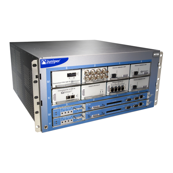
The M10i router supports up to eight Physical Interface Cards (PICs). The router height of 8.7 in. (22.1 cm) enables stacked installation of eight M10i routers in a single floor-to-ceiling rack, for increased port density per unit of floor space. -
Page 28: System Redundancy
FRUs that require powering off the router—You must power off the router before removing these components. Table 5 on page 4 lists the FRUs for the M10i router. Table 5: Field-Replaceable Units Hot-Removable and FRUs that require... -
Page 29: Dc System Redundancy
Chapter 1: System Overview DC System Redundancy DC system redundancy requires two power sources from feed A and two power sources from feed B. If one feed fails or is shut down for service, the other feed powers two DC power supplies and can provide full power to the router's components indefinitely. - Page 30 M10i Internet Router Hardware Guide Safety Requirements, Warnings, and Guidelines...
-
Page 31: Hardware Component Overview
The chassis is 17.5 in. (44.5 cm) wide and 18 in. (45.7 cm) deep. The chassis height of 8.7 in. (22.1 cm) enables stacked installation of eight M10i routers in a single floor-to-ceiling rack. For more information, see “Rack on page 42. -
Page 32: Figure 1: Front Of Chassis
M10i Internet Router Hardware Guide Figure 1: Front of Chassis Figure 2: Rear of Chassis The chassis includes an electrostatic discharge (ESD) point (banana plug receptacle) to protect electronic components from damage due to static electricity, at the front of the chassis, as shown in... -
Page 33: Midplane
Chapter 2: Hardware Component Overview For further safety information, see “Safety and Regulatory Compliance on page 135. Information” on page 9 summarizes physical specifications for the router chassis. Table 6 Table 6: Chassis Physical Specifications Description Value Chassis height 8.7 in. (22.1 cm) Chassis width 17.5 in. -
Page 34: Flexible Pic Concentrators (Fpcs)
10). “Physical Interface Cards (PICs)” On the M10i router, each FPC is built in (it cannot be removed from the chassis as on other M-series platforms) and corresponds to a horizontal row of PIC slots. The two FPCs on the M10i router are numbered , top to bottom. -
Page 35: Pic Components
96. “Replacing a PIC” PIC Components Most PICs supported on the M10i router have the following components. For complete specifications, see the M10i Internet Router PIC Guide. For information about pinouts for PIC cable connectors, see “Cable Connector Pinouts”... -
Page 36: Cfeb Components
M10i Internet Router Hardware Guide For CFEB replacement instructions, see “Replacing a CFEB” on page 90. The CFEB communicates with the Routing Engine using a dedicated 100-Mbps Fast Ethernet link that transfers routing table data from the Routing Engine to the forwarding table in the integrated ASIC. -
Page 37: Table 7: States For Cfeb Leds
Chapter 2: Hardware Component Overview I 2 C/EEPROM containing the serial number and revision level Two 512-KB boot flash EPROMs (programmable on the board) One PowerPC 8245 integrated processor Three LEDs—A green LED labeled , a red LED labeled , and a blue LED FAIL labeled indicate CFEB status. -
Page 38: Routing Engine
Routing Engine redundancy in the JUNOS System Basics Configuration Guide. We recommend you run JUNOS Release 7.0 or later on the M10i router to support graceful switchover. For replacement instructions, see “Replacing the Routing Engine”... - Page 39 Chapter 2: Hardware Component Overview CPU—Runs JUNOS Internet software to maintain the router's routing tables and routing protocols. It has a Pentium-class processor. SDRAM—Provides storage for the routing and forwarding tables and for other Routing Engine processes. Internal flash drive—This drive is optional. If installed, it provides primary storage. It holds software images, configuration files, and microcode.
-
Page 40: Routing Engine Interface Ports
M10i Internet Router Hardware Guide Figure 5: Routing Engine Table 8: States for Routing Engine LEDs Label Color State Description Green Blinking There is read/write activity on the PC card. Blue On steadily Routing Engine is functioning as master. MASTER On steadily Routing Engine is not operational. -
Page 41: High-Availability Chassis Manager (Hcm)
Chapter 2: Hardware Component Overview For information about the pinouts for the connectors, see “Cable Connector Pinouts” on page 199. High-Availability Chassis Manager (HCM) The High-Availability Chassis Manager (HCM) works with its companion Routing Engine to provide control and monitoring functions for router components. The HCM also displays alarm status and takes PICs online and offline. -
Page 42: Alarm Leds
M10i Internet Router Hardware Guide 100-Mbps Fast Ethernet switch—Carries signals and monitoring data between router components. Two LEDs—Indicate HCM status. There is a green one labeled and an blue one labeled on page 18 describes the LED states. MSTR Table 9 Alarm LEDs—Display alarm conditions, if any exist. -
Page 43: Pic Offline Buttons
Chapter 2: Hardware Component Overview Table 10 on page 19 describes the alarm LEDs in more detail. Table 10: Alarm LEDs Shape Color State Description On steadily Critical alarm LED—Indicates a critical condition that can cause the router to stop functioning, such as component removal, failure, or overheating. -
Page 44: Ac Power Supply
M10i Internet Router Hardware Guide Power supplies are hot-removable and hot-insertable, as described in “Field-Replaceable Units (FRUs)” on page 3. To avoid electrical injury, carefully follow the instructions on page 107 and “Replacing an AC Power Supply” “Replacing a DC Power on page 112. -
Page 45: Dc Power Supply
Chapter 2: Hardware Component Overview Figure 7: AC Power Supply Table 11: Electrical Specifications for AC Power Supply Description Specification Maximum power output 293 WDC AC input voltage Nominal: 100, 120, 200, 208, 220, 240 VAC Operating range: 90–264 VAC AC input line frequency 47–63 Hz AC input current rating... -
Page 46: Power Supply Led
M10i Internet Router Hardware Guide Figure 8: DC Power Supply Table 12: Electrical Specifications for DC Power Supply Description Specification Maximum power output 293 W DC input voltage Nominal: –48, –60 VDC Operating range: –40.5 to –72 VDC Input DC current rating 10 A @ –48 V... -
Page 47: Fan Tray
Chapter 2: Hardware Component Overview Fan Tray The router's cooling system consists of two fan trays, located along the left and right side of the chassis, that provide side-to-side cooling (see Figure 9 ). They connect directly to the router midplane. Each fan tray is a single unit containing eight individually fault-tolerant fans. -
Page 48: Figure 10: Cable Management System
M10i Internet Router Hardware Guide Figure 10: Cable Management System Cable Management System... -
Page 49: Chapter 3 Junos Internet Software Overview
Chapter 3 JUNOS Internet Software Overview The JUNOS Internet software is especially designed for the large production networks typically supported by Internet Service Providers (ISPs). It incorporates Internet Protocol (IP) routing software and software for management of interfaces, networks, and the router chassis. The JUNOS Internet software runs on the Routing Engine. -
Page 50: Routing Protocol Process
M10i Internet Router Hardware Guide Routing Protocol Process on page 26 on page 30 VPNs Interface Process on page 31 Chassis Process on page 31 on page 31 SNMP and MIB II Processes Management Process on page 31 on page 31... - Page 51 Chapter 3: JUNOS Internet Software Overview BGP—Border Gateway Protocol, version 4, is an Exterior Gateway Protocol (EGP) that guarantees loop-free exchange of routing information between routing domains (also called autonomous systems). BGP, in conjunction with JUNOS routing policy, provides a system of administrative checks and balances that can be used to implement peering and transit agreements.
-
Page 52: Ipv6 Routing Protocols
M10i Internet Router Hardware Guide by LDP can also traverse LSPs created by Resource Reservation Protocol (RSVP). MPLS—Multiprotocol Label Switching enables you to configure LSPs through a network either manually or dynamically. You can control how traffic traverses the network by directing it through particular paths, rather than relying on an IGP's least-cost algorithm to choose a path. -
Page 53: Routing And Forwarding Tables
Chapter 3: JUNOS Internet Software Overview Routing and Forwarding Tables The primary function of the JUNOS routing protocol process is maintaining routing tables and using the information in them to determine active routes to network destinations. It copies information about the active routes into the Routing Engine's forwarding table, which the JUNOS kernel copies to the Packet Forwarding Engine. -
Page 54: Vpns
M10i Internet Router Hardware Guide RIP) export the direct (interface) routes for the interfaces on which the protocol is explicitly configured. For each routing table, you can affect the routes that a protocol places into the table and the routes from the table that the protocol advertises by defining one or more routing policies and then applying them to the specific routing protocol. -
Page 55: Interface Process
Chapter 3: JUNOS Internet Software Overview by a VPN customer with connections to several various ISPs, or different connections to the same ISP in various geographic regions. Carrier-of-Carrier VPNs—Carrier-of-carrier VPNs allow a VPN service provider to supply VPN service to a customer who is also a service provider. The latter service provider supplies Internet or VPN service to an end customer. -
Page 56: Tools For Accessing And Configuring The Software
M10i Internet Router Hardware Guide Tools for Accessing and Configuring the Software The JUNOS CLI is the primary tool for accessing and controlling the JUNOS Internet software. You use it when accessing the router through the console or a connection to an out-of-band management network. -
Page 57: Chapter 4 System Architecture Overview
Chapter 4 System Architecture Overview The router architecture consists of two major components: Packet Forwarding Engine—Performs Layer 2 and Layer 3 packet switching, route lookups, and packet forwarding. Routing Engine—Provides Layer 3 routing services and network management. The Packet Forwarding Engine and the Routing Engine perform independently but communicate constantly through a 100-Mbps internal link. -
Page 58: Data Flow Through The Packet Forwarding Engine
M10i Internet Router Hardware Guide Midplane—Transports packets, notifications, and other signals between the PICs and the Packet Forwarding Engine (as well as other system components). Physical Interface Card (PIC)—Physically connects the router to fiber-optic or digital network media. A controller ASIC in each PIC performs control functions specific to the PIC media type. -
Page 59: Routing Engine Architecture
Routing Engine Architecture The Routing Engine is an Intel-based PCI platform running the JUNOS Internet software, which Juniper Networks has developed and optimized to handle large numbers of network interfaces and routes. The software consists of a set of system processes running in protected memory modules on top of an independent operating system. -
Page 60: Routing Engine Functions
M10i Internet Router Hardware Guide Routing Engine Functions The Routing Engine handles all routing protocol processes, as well as the software processes that control the router's interfaces, the chassis components, system management, and user access to the router. These routing and software processes run on top of a kernel that interacts with the Packet Forwarding Engine. -
Page 61: Figure 14: Control Packet Handling For Routing And Forwarding Table Updates
Chapter 4: System Architecture Overview Figure 14: Control Packet Handling for Routing and Forwarding Table Updates Routing Engine Architecture... - Page 62 M10i Internet Router Hardware Guide Routing Engine Architecture...
- Page 63 Part 2 Initial Installation on page 41 Preparing for Router Installation on page 47 Unpacking the Router Installing the Mounting Hardware on page 51 Installing the Router on page 55 Connecting the Router on page 59 Performing the Initial Configuration on page 67 Initial Installation...
-
Page 64: Part 2 Initial Installation
M10i Internet Router Hardware Guide Initial Installation... -
Page 65: Preparing For Router Installation
Chapter 5 Preparing for Router Installation This chapter describes how to prepare your site for installation of the M10i Internet router. It discusses the following topics: Site Preparation Checklist on page 41 on page 42 Rack Requirements on page 44... -
Page 66: Rack Requirements
M10i Internet Router Hardware Guide Table 14: Site Preparation Checklist (continued) Item or Task For More Information Performed By Date Plan rack location, including required space “Clearance Requirements for Airflow clearances. and Hardware Maintenance” on page 44 “Rack Size and Strength” on page 42 If a rack is used, secure rack to floor and “Connection to Building... -
Page 67: Figure 15: Typical Open-Frame Rack
Chapter 5: Preparing for Router Installation NOTE: We recommend that you do not install the router in a cabinet. If you mount the router in a cabinet, be sure that sufficient room is provided for cable management and cables. The rack rails must be spaced widely enough to accommodate the router chassis's external dimensions: 8.7 in. -
Page 68: Spacing Of Mounting Holes
M10i Internet Router Hardware Guide Spacing of Mounting Holes The holes in the mounting brackets are spaced at 1 U (1.75 in. or 4.45 cm), so the router can be mounted in any rack that provides holes spaced at that distance. -
Page 69: Figure 16: Chassis Dimensions And Clearance Requirements
Chapter 5: Preparing for Router Installation Figure 16: Chassis Dimensions and Clearance Requirements Clearance Requirements for Airflow and Hardware Maintenance... - Page 70 M10i Internet Router Hardware Guide Clearance Requirements for Airflow and Hardware Maintenance...
-
Page 71: Chapter 6 Unpacking The Router
Unpacking the Router The router is shipped in a cardboard carton, held in place with foam packing material. The crate also contains an accessory box, the front-mounting shelf, and the M10i Internet Router Installation Quick Start. NOTE: The router is maximally protected inside the shipping carton. Do not unpack it until you are ready to begin installation. -
Page 72: Figure 4: Cfeb
M10i Internet Router Hardware Guide Remove the accessory box and packing material from the top of the router. Open the accessory box and verify the contents against the parts inventory on the label attached to the box. Remove the router from the shipping carton. - Page 73 Chapter 6: Unpacking the Router Table 15: Generic Inventory of Router Components (continued) Component Quantity Routing Engine Up to 2 Blank panels for slots without components Depends on router configuration Unpacking the Router...
- Page 74 M10i Internet Router Hardware Guide Unpacking the Router...
-
Page 75: Chapter 7 Installing The Mounting Hardware
Chapter 7 Installing the Mounting Hardware In a four-post rack or cabinet, you front-mount the router. In an open-frame rack, you can center-mount or front-mount the router. In an open-frame rack, center-mounting provides more even distribution of weight and greater stability. If you are installing the router in a four-post rack or cabinet, or front-mounting it in an open-frame rack, we recommend using a shelf to support the router. -
Page 76: Installing The Cable Management System
M10i Internet Router Hardware Guide Replace the screws that secure the mounting brackets to the chassis. Reinstall the fan trays: Grasp the handle on the faceplate of the fan tray with one hand and place the other hand under the unit to support it. Orient the fan tray so that the thumbscrew is at the top of the tray. - Page 77 Chapter 7: Installing the Mounting Hardware Figure 19: Installing the Cable Management System Installing the Cable Management System...
-
Page 78: Figure 19: Installing The Cable Management System
M10i Internet Router Hardware Guide Installing the Cable Management System... -
Page 79: Chapter 8 Installing The Router
Chapter 8 Installing the Router Because the router weighs between 57 lb (25.9 kg) and about 79 lb (35.8 kg), using a mechanical lift to install it is recommended. If you do not use a mechanical lift, installing the chassis safely requires two people to lift and an additional person to insert the mounting screws. - Page 80 M10i Internet Router Hardware Guide Read the information in “Installation Safety Guidelines and Warnings” on page 153, with particular attention to “Chassis Lifting Guidelines” on page 154. Remove the router from the shipping carton, as described in “Unpacking the Router”...
-
Page 81: Figure 20: Installing The Chassis Into A Open-Frame Rack
Chapter 8: Installing the Router Figure 20: Installing the Chassis into a Open-Frame Rack Installing the Chassis in the Rack... -
Page 82: Figure 21: Installing The Chassis Into A Four-Post Rack
M10i Internet Router Hardware Guide Figure 21: Installing the Chassis into a Four-Post Rack Installing the Chassis in the Rack... -
Page 83: Connecting The Router
Chapter 9 Connecting the Router After installing the router into the rack as described in “Initial Installation” on page 39, complete the installation by connecting management and alarm devices, PICs, and power cables. This chapter has the following sections: on page 59 Tools and Parts Required Connecting the Router to Management Devices on page 59... -
Page 84: Connecting To A Network For Out-Of-Band Management
M10i Internet Router Hardware Guide Connecting to a Management Console or Auxiliary Device on page 60 Connecting to a Network for Out-of-Band Management To connect the Routing Engine to a network for out-of-band management, connect an Ethernet cable with RJ-45/RJ-45 connectors to the... -
Page 85: Connecting Pic Cables
, which shows a fiber-optic PIC): Have ready a length of the type of cable used by the PIC. For cable specifications, see the M10i Internet Router PIC Guide. If the PIC cable connector port is covered by a rubber safety plug, remove the plug. -
Page 86: Providing Power To The Router
M10i Internet Router Hardware Guide Figure 25: Attaching Cable to a PIC Providing Power to the Router Connect the router to external power sources and power it on by performing the following procedures: Connecting Power to an AC-Powered Router on page 62... -
Page 87: Connecting Power To A Dc-Powered Router
Chapter 9: Connecting the Router Verify that the switch on each power supply faceplate is in the ) position. For each power supply, insert the appliance coupler end of a power cord into the appliance inlet on a power supply faceplate and insert the plug into an AC power source receptacle. -
Page 88: Figure 26: Connecting Dc Power And Grounding Cables
M10i Internet Router Hardware Guide Insert the power cable lugs into the appropriate field-wiring terminals. Using a number 1 Phillips screwdriver, turn the screw on each field-wiring terminal clockwise to secure the power cable lug. Apply between 8 lb-in. (.9 Nm) and 9 lb-in. -
Page 89: Powering On The Router
Chapter 9: Connecting the Router Powering On the Router To power on the router, follow this procedure: Verify that the power supplies are fully inserted in the chassis and the thumbscrews on their faceplates are tightened. For each power supply on an AC-powered router, verify that the ends of the power cord are firmly plugged into the appliance inlet on the power supply faceplate and the external power source receptacle. - Page 90 M10i Internet Router Hardware Guide “Connecting Power to an AC-Powered Router” on page 62 or “Connecting Power to a DC-Powered Router” on page 63. On the external management device connected to the Routing Engine, monitor the startup process to verify that the system has booted properly.
-
Page 91: Chapter 10 Performing The Initial Configuration
Chapter 10 Performing the Initial Configuration Configuring the JUNOS Internet Software on page 67 Configuring the JUNOS Internet Software The router is shipped with the JUNOS Internet software preinstalled and ready to be configured when the router is powered on. There are three copies of the software: one on a nonrotating flash drive in the Routing Engine, one on a rotating hard disk in the Routing Engine, and one on a PC card that can be inserted into the slot in the Routing Engine faceplate. - Page 92 M10i Internet Router Hardware Guide root# cli root@> Enter configuration mode. cli> configure [edit] root@# Configure the name of the router. If the name includes spaces, enclose the name in quotation marks (“ ”). [edit] root@# set system host-name host-name Configure the router's domain name.
- Page 93 Chapter 10: Performing the Initial Configuration [edit] root@# set system root-authentication ssh-rsa public-key Optionally, display the configuration to verify that it is correct. [edit] root@# show system { host-name host-name; domain-name domain-name; backup-router address; root-authentication { authentication-method (password | public-key); name-server { address;...
- Page 94 M10i Internet Router Hardware Guide Configuring the JUNOS Internet Software...
-
Page 95: Hardware Maintenance, Troubleshooting, And Replacement Procedures
Part 3 Hardware Maintenance, Troubleshooting, and Replacement Procedures on page 73 Maintaining Hardware Components on page 79 Troubleshooting Hardware Components on page 87 Replacing Hardware Components Hardware Maintenance, Troubleshooting, and Replacement Procedures... - Page 96 M10i Internet Router Hardware Guide Hardware Maintenance, Troubleshooting, and Replacement Procedures...
-
Page 97: Maintaining Hardware Components
Maintaining Hardware Components This chapter describes how to maintain hardware components installed in the router. For information about returning a part to Juniper Networks for repair or replacement, see “Contacting Customer Support and Returning Hardware” on page 189. on page 73... -
Page 98: Maintaining The Fan Tray
. Some PICs have additional LEDs, often one per port. The meaning of the LED states differs for various PICs. For more information, see the M10i Internet Router PIC Guide. If the FPC that houses the PIC detects a PIC failure, the FPC generates an alarm message to be sent to the Routing Engine. - Page 99 Chapter 11: Maintaining Hardware Components user@host> show chassis fpc pic-status Slot 0 Online PIC 0 4x OC-3 SONET, MM PIC 1 1x CSTM1, SMIR PIC 3 2x OC-3 ATM, MM Slot 1 Online PIC 0 1x OC-12 SONET, MM PIC 1 1x OC-12 ATM, MM PIC 2 2x OC-3 ATM, MM...
-
Page 100: Maintaining The Power Supplies
M10i Internet Router Hardware Guide unplugging is then absorbed by the short fiber extension, which is easy and inexpensive to replace. Keep fiber-optic cable connections clean. Small micro-deposits of oil and dust in the canal of the transceiver or cable connector could cause loss of light, reducing signal power and possibly causing intermittent problems with the optical connection. -
Page 101: Maintaining The Routing Engine
Chapter 11: Maintaining Hardware Components Verify that the power source has the proper current rating and that each power supply is connected to a separate power source. Verify that the cable or cord connecting the power supply to the external power source is securely in place and that there is no moisture accumulating near the router. - Page 102 M10i Internet Router Hardware Guide Maintaining the Routing Engine...
-
Page 103: Troubleshooting Hardware Components
This chapter describes how to troubleshoot problems with hardware components installed in the router. If you encounter software problems, or problems with hardware components not discussed here, contact the Juniper Networks Technical Assistance Center (JTAC) as described in “Requesting Support” on page xxiv. -
Page 104: Leds
Some PICs have STATUS additional LEDs, often one per port. The meaning of the LED states differs for various PICs. For more information, see the M10i Internet Router PIC Guide. Power supply—A green LED labeled reports the status of the power OUTPUT OK supply. -
Page 105: Table 16: Chassis Alarm Messages
A CFEB mirocode download has Replace failed CFEB. failed. A fan has failed. Replace failed fan Fan Trays tray. For an M10i router, both fan trays Install missing fan are absent from the chassis. tray. Too many hot-swap interrupts are Contact technical Hot swapping occurring. -
Page 106: Table 17: Sonet/Sdh Interface Alarm Messages
M10i Internet Router Hardware Guide Table 16: Chassis Alarm Messages (continued) Chassis Alarm Component Alarm Condition Remedy Severity Reformat internal flash drive and install bootable image. If this fails, replace failed Routing Engine. System booted from hard disk. This Install bootable image... -
Page 107: Juniper Networks Technical Assistance Center
- SONET severely errored frame interface-name so-x/x/x - SONET unequipped Juniper Networks Technical Assistance Center If you need assistance during troubleshooting, you can contact the Juniper Networks Technical Assistance Center (JTAC) by using the Web or telephone. See “Requesting on page xxiv. -
Page 108: Troubleshooting The Fan Tray
To check the status of each port on a PIC, look at the LED located on the PIC faceplate. For information about the meaning of LED states on different PICs, see the M10i Internet Router PIC Guide. To check the status of a PIC, issue the following CLI command. The PIC slots in... -
Page 109: Troubleshooting The Power System
Chapter 12: Troubleshooting Hardware Components user@host> show chassis fpc pic-status Slot 0 Online PIC 0 4x OC-3 SONET, MM PIC 1 1x CSTM1, SMIR PIC 3 2x OC-3 ATM, MM Slot 1 Online PIC 0 1x OC-12 SONET, MM PIC 1 1x OC-12 ATM, MM PIC 2 2x OC-3 ATM, MM... - Page 110 AC Power Supply” “Replacing a DC Power Supply” If the LED lights correctly on the spare, the original power supply is faulty. Return it to Juniper Networks for replacement, as described in “Contacting Customer Support and Returning Hardware” on page 189.
-
Page 111: Replacing Hardware Components
(FRU) that contains the component. For instructions, see on page 189. For a list of the “Contacting Customer Support and Returning Hardware” FRUs on the M10i routers, see “Field-Replaceable Units (FRUs)” on page 3. Tools and Parts Required on page 87... -
Page 112: Replacing A Fan Tray
M10i Internet Router Hardware Guide Table 18: Tools and Parts Required (continued) Tool or part Components Flat-blade (–) screwdriver, 2.5 mm Serial cable to Routing Engine AUX/MODEM CONSOLE port Needlenose pliers Internal flash drive Phillips (+) screwdrivers, numbers Fan tray... -
Page 113: Installing A Fan Tray
Chapter 13: Replacing Hardware Components Grasp the handle on the faceplate and slide the tray about halfway out of the chassis. CAUTION: To avoid injury, keep tools and your fingers away from the fans as you slide the fan tray out of the chassis. The fans might still be spinning. Place one hand under the fan tray to support it and slide the tray completely out of the chassis after the fans stop spinning. -
Page 114: Replacing A Cfeb
M10i Internet Router Hardware Guide Figure 28: Installing a Fan Tray Replacing a CFEB One or two CFEBs can install into the uppermost slots in the rear of the chassis, as shown in Figure 2 . Only one CFEB is active at a time, with the optional second CFEB in reset mode. -
Page 115: Installing A Cfeb
Chapter 13: Replacing Hardware Components (The effect of removing the active CFEB depends on whether a second CFEB is installed. For more information, see “Replacing a CFEB” on page 90.) Loosen the thumbscrew on each ejector lever (shown in Figure 4 ), using a Phillips screwdriver if necessary. -
Page 116: Replacing An Hcm
M10i Internet Router Hardware Guide Align the rear of the CFEB with the guides inside the chassis and slide it in completely. Press the ejector lever at each end of the CFEB inward. Tighten the thumbscrew on each ejector lever (shown in... - Page 117 Routing Engine redundancy in the JUNOS System Basics Configuration Guide. We recommend you run JUNOS Release 7.0 or later on the M10i router to support graceful switchover. NOTE: Router performance might change if the standby Routing Engine's configuration differs from the former master's configuration.
- Page 118 M10i Internet Router Hardware Guide NOTE: Wait until a message appears on the console confirming that the operating system has halted. For more information about the command, see the JUNOS System Basics and Services Command Reference. NOTE: The router might continue forwarding traffic for a few minutes after the request system halt command has been issued.
-
Page 119: Installing An Hcm
Chapter 13: Replacing Hardware Components Figure 31: Removing a Routing Engine Figure 32: Removing an HCM Installing an HCM To install an HCM, follow this procedure (see Figure 33 Figure 34 Attach an electrostatic discharge (ESD) grounding strap to your bare wrist and connect the strap to one of the ESD points on the chassis. -
Page 120: Replacing A Pic
Figure 33: Installing the HCM Figure 34: Installing a Routing Engine Replacing a PIC Up to eight regular PICs install into an M10i router, as shown in Figure 1 . Quad-wide PICs occupy all four slots in an FPC row. -
Page 121: Removing A Pic
5 seconds. The failure LED is usually red; for more information, see the M10i Internet Router PIC Guide. The offline button for each PIC is located on the HCM and is labeled with the PIC slot number. The... - Page 122 M10i Internet Router Hardware Guide that use it (such as ATM and SONET/SDH interfaces) emit laser light that can damage your eyes. CAUTION: Do not leave a fiber-optic transceiver uncovered except when inserting or removing cable. The safety cap keeps the port clean and prevents accidental exposure to laser light.
-
Page 123: Installing A Pic
Chapter 13: Replacing Hardware Components Figure 35: Removing a PIC Installing a PIC To install a PIC, follow this procedure (see Figure 36 Attach an electrostatic discharge (ESD) grounding strap to your bare wrist and connect the strap to one of the ESD points on the chassis. Make sure the router is attached to a proper earth ground. - Page 124 M10i Internet Router Hardware Guide If the PIC uses fiber-optic cable, remove the rubber safety cap from each transceiver and the end of each cable. WARNING: Do not look directly into the ends of fiber-optic cables or into the transceivers on the interface faceplate. Single-mode fiber-optic cable and the interfaces that use it (such as ATM and SONET/SDH interfaces) emit laser light that can damage your eyes.
-
Page 125: Replacing Pic Cables
Press and hold the PIC offline button until the status LED on the PIC faceplate indicates normal functioning, which usually takes about 5 seconds. The LED is usually green; for more information, see the M10i Internet Router PIC Guide. The offline button for each PIC is located on the HCM and is labeled with the PIC slot number. -
Page 126: Installing A Pic Cable
5 seconds. The failure LED is usually red; for more information, see the M10i Internet Router PIC Guide. The offline button for each PIC is located on the HCM and is labeled with the PIC slot number. The... - Page 127 Chapter 13: Replacing Hardware Components Have ready a length of the type of cable used by the PIC. For cable specifications, see the M10i Internet Router PIC Guide. If the PIC cable connector port is covered by a rubber safety plug, remove the plug.
-
Page 128: Replacing An Sfp
Press and hold the PIC offline button until the status LED on the PIC faceplate indicates normal functioning, which usually takes about 5 seconds. The LED is usually green; for more information, see the M10i Internet Router PIC Guide. The offline button for each PIC is located on the HCM and is labeled with the PIC slot number. -
Page 129: Removing An Sfp
Chapter 13: Replacing Hardware Components Figure 38: Small Form-Factor Pluggable (SFP) SFPs are hot-insertable and hot-removable. Removing an SFP does not interrupt PIC functioning, but the removed SFP no longer receives or transmits data. To replace an SFP, perform the following procedures: on page 105 Removing an SFP on page 106... -
Page 130: Installing An Sfp
M10i Internet Router Hardware Guide Place an electrostatic bag or antistatic mat on a flat, stable surface to receive the SFP. Have ready a rubber safety cap for the SFP transceiver and the cable. Attach an electrostatic discharge (ESD) grounding strap to your bare wrist and connect the strap to one of the ESD points on the chassis. -
Page 131: Replacing Power System Components
Verify that the status LEDs on the PIC faceplate indicate that the SFP is functioning correctly (there is an LED for each SFP port). For more information about the PIC LEDs, see the M10i Internet Router PIC Guide. You can also verify PIC functioning by issuing the... -
Page 132: Removing An Ac Power Supply
M10i Internet Router Hardware Guide (FRUs)” on page 3. For more information about AC power supplies, see “AC Power Supply” on page 20. To replace an AC power supply, perform the following procedures: on page 108 Removing an AC Power Supply... -
Page 133: Installing An Ac Power Supply
Chapter 13: Replacing Hardware Components Figure 39: Removing an AC Power Supply Installing an AC Power Supply To install an AC power supply, follow this procedure (see Figure 40 Verify that the switch on the power supply faceplate is in the ) position. -
Page 134: Disconnecting And Connecting Ac Power
M10i Internet Router Hardware Guide receptacle. Verify that the power cord does not block access to router components or drape where people could trip on it. Press the power switch on the faceplate to the ) position.When the power supply has powered on successfully, the green OUTPUT OK LED lights steadily. -
Page 135: Disconnecting Ac Power From The Router
Chapter 13: Replacing Hardware Components Disconnecting AC Power from the Router To disconnect AC power from the router, follow this procedure: On the console or other management device connected to the Routing Engine, enter CLI operational mode and issue the following command to shut down the router software cleanly and preserve Routing Engine state information. -
Page 136: Replacing A Dc Power Supply
M10i Internet Router Hardware Guide Press the power switches on the faceplates of two power supplies to the position. When the power supply has powered on successfully, the green OUTPUT OK LED lights steadily. NOTE: After powering off a power supply, wait at least 60 seconds before turning it back on. -
Page 137: Removing A Dc Power Supply
Chapter 13: Replacing Hardware Components Removing a DC Power Supply The DC power supplies are located at the bottom rear of the chassis, as shown in . For information about power supply redundancy and replaceability, see Figure 2 on page 19. “Power Supplies”... -
Page 138: Installing A Dc Power Supply
M10i Internet Router Hardware Guide Figure 41: Removing a DC Power Supply Installing a DC Power Supply To install a DC power supply, follow this procedure (see Figure 42 Figure 43 Verify that there is no power flowing to the power supply from the external power source, so that the voltage across the leads of the power cables is 0 V. - Page 139 Chapter 13: Replacing Hardware Components clockwise to secure the power cable lug. Apply between 8 lb-in. (.9 Nm) and 9 lb-in. (1.02 Nm) of torque to each screw. Insert the positive (+) source cable into the return terminal, which is labeled Insert the negative (–) source cable into the input terminal, which is labeled NOTE: The DC power supplies in slots must be powered by dedicated...
-
Page 140: Disconnecting And Connecting Dc Power
M10i Internet Router Hardware Guide Figure 42: Installing a DC Power Supply Figure 43: Connecting Power Cables to a DC Power Supply Disconnecting and Connecting DC Power On a DC-powered router, the power cables from the external DC power sources connect to field-wiring terminals on each power supply. -
Page 141: Disconnecting Dc Power From The Router
Chapter 13: Replacing Hardware Components Connecting DC Power to the Router on page 118 Disconnecting DC Power from the Router To disconnect DC power from the router, follow this procedure: On the console or other management device connected to the Routing Engine, enter CLI operational mode and issue the following command to shut down the router software cleanly and preserve Routing Engine state information. -
Page 142: Connecting Dc Power To The Router
M10i Internet Router Hardware Guide Connecting DC Power to the Router Connect DC power to the router by inserting power cables into the field-wiring terminals on the faceplate of each power supply. Power and grounding cables are not supplied with the router. For information about the required cable type, see “DC... - Page 143 Chapter 13: Replacing Hardware Components Insert the negative (–) source cable into the input terminal, which is labeled NOTE: The DC power supplies in slots must be powered by dedicated P/S 0 P/S 1 power feeds derived from feed A, and the DC power supplies in slots P/S 2 must be powered by dedicated power feeds derived from feed B.
-
Page 144: Replacing Routing Engine Components
M10i Internet Router Hardware Guide If the LEDs are not lit in the appropriate pattern after 60 seconds, repeat the power supply and cable installation procedures described in “Installing a DC Power Supply” on page 114 and the previous steps in this section. -
Page 145: Replacing The Routing Engine
Chapter 13: Replacing Hardware Components Replacing the Routing Engine The Routing Engines are hot-pluggable, as described in “Field-Replaceable Units on page 3. For a description of the effect of removing a Routing Engine, (FRUs)” on page 14. To replace a Routing Engine, perform the following “Routing Engine”... - Page 146 M10i Internet Router Hardware Guide We recommend you run JUNOS Release 7.0 or later on the M10i router to support graceful switchover. NOTE: Router performance might change if the standby Routing Engine's configuration differs from the former master's configuration. For the most predictable...
-
Page 147: Installing A Routing Engine
Chapter 13: Replacing Hardware Components Place one hand under the Routing Engine to support it, slide it completely out of the chassis, and place it on the antistatic mat or in the electrostatic bag. Figure 45: Removing a Routing Engine Installing a Routing Engine To install a Routing Engine, follow this procedure (see Figure 46... -
Page 148: Removing And Inserting The Pc Card
Routing Engine onto a PC Card, for example, to create a backup copy of upgrade software that you have obtained from Juniper Networks. Instructions for copying software to a PC Card are available at the Juniper Networks Support Web site ); after logging in, navigate to the Customer Support http://www.juniper.net/support/... -
Page 149: Inserting The Pc Card
To insert the PC card, follow this procedure (see Figure 48 Orient the PC card with the Juniper Networks logo facing in the direction specified on the Routing Engine faceplate. Insert the card into the slot. Press the card firmly all the way into the slot. Note that the PC card slot might... -
Page 150: Removing And Inserting The Internal Flash Drive
Figure 48: Inserting the PC Card Removing and Inserting the Internal Flash Drive The internal flash drive is an optional component of the M10i router. If installed, it provides primary storage for the router. It accommodates software images, configuration files, and microcode. -
Page 151: Inserting The Internal Compact Flash Disk
Chapter 13: Replacing Hardware Components is attached to a proper earth ground. For more information about ESD, see “Preventing Electrostatic Discharge Damage” on page 140. Remove the Routing Engine as described in “Removing a Routing Engine” on page 121. Use needlenose pliers with grooved jaws to pull the wire clasp out from under the compact flash disk and lift it up (see Figure 49 Use the needlenose pliers to gently grasp the compact flash disk and slide it out... -
Page 152: Configuring The Internal Compact Flash Disk
M10i Internet Router Hardware Guide Figure 50: Inserting the Internal Flash Drive Configuring the Internal Compact Flash Disk After installing the internal compact flash disk for the first time, you must copy the software from the Routing Engine's hard disk to the internal compact flash disk. -
Page 153: Removing And Inserting Sdram Modules
Chapter 13: Replacing Hardware Components The internal compact flash disk will now be the primary boot device. You can verify correct boot order by issuing the show system boot-messages command. The output lists the devices mounted. The internal compact flash disk is located at For more information about the command, see the JUNOS System Basics and Services Command Reference. -
Page 154: Replacing Connectors To Routing Engine Interface Ports
M10i Internet Router Hardware Guide Attach an electrostatic discharge (ESD) grounding strap to your bare wrist and connect the strap to one of the ESD points on the chassis. Make sure the router is attached to a proper earth ground. For more information about ESD, see “Preventing Electrostatic Discharge Damage”... -
Page 155: Replacing The Management Ethernet Cable
Chapter 13: Replacing Hardware Components Replacing the Management Ethernet Cable on page 131 on page 131 Replacing the Console or Auxiliary Cable Replacing the Management Ethernet Cable To connect the Routing Engine to a network for out-of-band management, connect an Ethernet cable with RJ-45/RJ-45 connectors to the port on the Routing MGMT Engine. -
Page 156: Figure 54: Console And Auxiliary Serial Port Connector
M10i Internet Router Hardware Guide Pull the cable connector straight out of the port. Disconnect the cable from the console or auxiliary device. Plug the female end of the replacement serial cable into the appropriate CONSOLE port. shows the external device ports on the Routing... - Page 157 Part 4 Appendixes on page 135 Safety and Regulatory Compliance Information on page 173 Environmental Specifications Power Requirements, Guidelines, and Specifications on page 175 Cable Specifications on page 183 Contacting Customer Support and Returning Hardware on page 189 Cable Connector Pinouts on page 199 Appendixes...
-
Page 158: Appendixes
M10i Internet Router Hardware Guide Appendixes... -
Page 159: Appendix A Safety And Regulatory Compliance Information
Appendix A Safety and Regulatory Compliance Information To install and use the router safely, follow proper safety procedures. This appendix discusses the following safety and regulatory compliance information: Definition of Safety Warning Levels on page 135 Safety Guidelines and Warnings on page 136 Definition of Safety Warning Levels This manual uses the following three levels of safety warnings:... -
Page 160: Safety Guidelines And Warnings
M10i Internet Router Hardware Guide Attention Ce symbole d'avertissement indique un danger. Vous vous trouvez dans une situation pouvant causer des blessures ou des dommages corporels. Avant de travailler sur un équipement, soyez conscient des dangers posés par les circuits électriques et familiarisez-vous avec les procédures couramment utilisées pour éviter... -
Page 161: General Safety Guidelines And Warnings
Appendix A: Safety and Regulatory Compliance Information Compliance Statements for Acoustic Noise on page 171 General Safety Guidelines and Warnings The following guidelines help ensure your safety and protect the router from damage. The list of guidelines might not address all potentially hazardous situations in your working environment, so be alert and exercise good judgment at all times. -
Page 162: Qualified Personnel Warning
M10i Internet Router Hardware Guide Restricted Access Area Warning on page 138 on page 140 Preventing Electrostatic Discharge Damage Qualified Personnel Warning WARNING: Only trained and qualified personnel should install or replace the router. Waarschuwing Installatie en reparaties mogen uitsluitend door getraind en bevoegd personeel uitgevoerd worden. - Page 163 Appendix A: Safety and Regulatory Compliance Information een slot en sleutel, of een ander veiligheidsmiddel, en welke beheerd wordt door de overheidsinstantie die verantwoordelijk is voor de locatie. Varoitus Tämä laite on tarkoitettu asennettavaksi paikkaan, johon pääsy on rajoitettua. Paikka, johon pääsy on rajoitettua, tarkoittaa paikkaa, johon vain huoltohenkilöstö pääsee jonkin erikoistyökalun, lukkoon sopivan avaimen tai jonkin muun turvalaitteen avulla ja joka on paikasta vastuussa olevien toimivaltaisten henkilöiden valvoma.
-
Page 164: Preventing Electrostatic Discharge Damage
M10i Internet Router Hardware Guide speciellt verktyg, lås och nyckel, eller annan säkerhetsanordning, och kontrolleras av den auktoritet som ansvarar för området. Preventing Electrostatic Discharge Damage Many router hardware components are sensitive to damage from static electricity. Some components can be impaired by voltages as low as 30 V. You can easily generate potentially damaging static voltages whenever you handle plastic or foam packing material or if you move components across plastic or carpets. -
Page 165: Fire Safety Requirements
In addition, you should establish procedures to protect your equipment in the event of a fire emergency. Juniper Networks products should be installed in an environment suitable for electronic equipment. We recommend that fire suppression equipment... -
Page 166: Electrical Safety Guidelines And Warnings
NOTE: To keep warranties effective, do not use a dry chemical fire extinguisher to control a fire at or near a Juniper Networks router. If a dry chemical fire extinguisher is used, the unit is no longer eligible for coverage under a service agreement. - Page 167 Appendix A: Safety and Regulatory Compliance Information Other countries—International Electromechanical Commission (IEC) 60364, Part 1 through Part 7. Evaluated to the TN power system. Locate the emergency power-off switch for the room in which you are working so that if an electrical accident occurs, you can quickly turn off the power. Do not work alone if potentially hazardous conditions exist anywhere in your workspace.
- Page 168 M10i Internet Router Hardware Guide Aviso Este equipamento deverá estar ligado à terra. Certifique-se que o host se encontra ligado à terra durante a sua utilização normal. ¡Atención! Este equipo debe conectarse a tierra. Asegurarse de que el equipo principal esté...
- Page 169 Appendix A: Safety and Regulatory Compliance Information Aviso Este dispositivo possui mais do que uma conexão de fonte de alimentação de energia; para poder remover a fonte de alimentação de energia, deverão ser desconectadas todas as conexões existentes. ¡Atención! Esta unidad tiene más de una conexión de suministros de alimentación; para eliminar la alimentación por completo, deben desconectarse completamente todas las conexiones.
- Page 170 M10i Internet Router Hardware Guide alterna (CA); cortar la alimentación desde el interruptor automático en los equipos de corriente continua (CC). Varning! Innan du arbetar med ett chassi eller nära strömförsörjningsenheter skall du för växelströmsenheter dra ur nätsladden och för likströmsenheter bryta strömmen vid överspänningsskyddet.
-
Page 171: Ac Power Electrical Safety Guidelines
Appendix A: Safety and Regulatory Compliance Information Warnung Verwenden Sie ausschließlich Kupferleiter. Avvertenza Usate unicamente dei conduttori di rame. Advarsel Bruk bare kobberledninger. Aviso Utilize apenas fios condutores de cobre. ¡Atención! Emplee sólo conductores de cobre. Varning! Använd endast ledare av koppar. AC Power Electrical Safety Guidelines The following electrical safety guidelines apply to AC-powered routers: AC-powered routers are shipped with a three-wire electrical cord with a... -
Page 172: Power Cable Warning (Japanese)
M10i Internet Router Hardware Guide Power Cable Warning (Japanese) WARNING: The attached power cable is only for this product. Do not use the cable for another product. DC Power Electrical Safety Guidelines and Warnings DC Power Electrical Safety Guidelines The following electrical safety guidelines apply to a DC-powered router: A DC-powered router is equipped with a DC terminal block that is rated for the power requirements of a maximally configured router. - Page 173 Appendix A: Safety and Regulatory Compliance Information Ensure that the polarity of the DC input wiring is correct. Under certain conditions, connections with reversed polarity might trip the primary circuit breaker or damage the equipment. For personal safety, connect the green and yellow wire to safety (earth) ground at both the router and the supply side of the DC wiring.
- Page 174 M10i Internet Router Hardware Guide circuito CC, mettere l'interruttore in posizione OFF e fissarlo con nastro adesivo in tale posizione. Advarsel Før noen av disse prosedyrene utføres, kontroller at strømmen er frakoblet likestrømkretsen. Sørg for at all strøm er slått AV. Dette gjøres ved å lokalisere strømbryteren på...
- Page 175 Appendix A: Safety and Regulatory Compliance Information Warnung Der Erdanschluß muß bei der Installation der Einheit immer zuerst hergestellt und zuletzt abgetrennt werden. Avvertenza In fase di installazione dell'unità, eseguire sempre per primo il collegamento a massa e disconnetterlo per ultimo. Advarsel Når enheten installeres, må...
- Page 176 M10i Internet Router Hardware Guide Avvertenza Mostra la morsettiera dell alimentatore CC. Cablare l'alimentatore CC usando i connettori adatti all'estremità del cablaggio, come illustrato. La corretta sequenza di cablaggio è da massa a massa, da positivo a positivo (da linea ad L) e da negativo a negativo (da neutro a N).
-
Page 177: Installation Safety Guidelines And Warnings
Appendix A: Safety and Regulatory Compliance Information Attention Quand des fils torsadés sont nécessaires, utiliser des douilles terminales homologuées telles que celles à circuit fermé ou du type à plage ouverte avec cosses rebroussées. Ces douilles terminales doivent être de la taille qui convient aux fils et doivent être refermées sur la gaine isolante et sur le conducteur. - Page 178 M10i Internet Router Hardware Guide Chassis Lifting Guidelines The weight of a fully configured chassis is about 79 lb (35.8 kg). Observe the following guidelines for lifting and moving the router: Before moving the router, read the guidelines in “Preparing for Router Installation”...
- Page 179 De onderstaande richtlijnen worden verstrekt om uw veiligheid te verzekeren: De Juniper Networks router moet in een stellage worden geïnstalleerd die aan een bouwsel is verankerd. Dit toestel dient onderaan in het rek gemonteerd te worden als het toestel het enige in het rek is.
- Page 180 Les directives ci-dessous sont destinées à assurer la protection du personnel: Le rack sur lequel est monté le Juniper Networks router doit être fixé à la structure du bâtiment. Si cette unité constitue la seule unité montée en casier, elle doit être placée dans le bas.
- Page 181 Appendix A: Safety and Regulatory Compliance Information Il Juniper Networks router deve essere installato in un telaio, il quale deve essere fissato alla struttura dell'edificio. Questa unità deve venire montata sul fondo del supporto, se si tratta dell'unica unità da montare nel supporto.
- Page 182 M10i Internet Router Hardware Guide El Juniper Networks router debe instalarse en un bastidor fijado a la estructura del edificio. Colocar el equipo en la parte inferior del bastidor, cuando sea la única unidad en el mismo. Cuando este equipo se vaya a instalar en un bastidor parcialmente ocupado, comenzar la instalación desde la parte inferior hacia la superior colocando el...
-
Page 183: Laser And Led Safety Guidelines And Warnings
Appendix A: Safety and Regulatory Compliance Information Aviso Não utilize uma rampa com uma inclinação superior a 10 graus. ¡Atención! No usar una rampa inclinada más de 10 grados Varning! Använd inte ramp med en lutning på mer än 10 grader. Laser and LED Safety Guidelines and Warnings Single-mode Physical Interface Cards (PICs) are equipped with laser transmitters, which are considered a Class 1 Laser Product by the U.S. - Page 184 M10i Internet Router Hardware Guide Waarschuwing Klasse-1 laser produkt. Varoitus Luokan 1 lasertuote. Attention Produit laser de classe I. Warnung Laserprodukt der Klasse 1. Avvertenza Prodotto laser di Classe 1. Advarsel Laserprodukt av klasse 1. Aviso Produto laser de classe 1.
- Page 185 Appendix A: Safety and Regulatory Compliance Information Varning! Lysdiodprodukt av klass 1. Laser Beam Warning WARNING: Do not stare into the laser beam or view it directly with optical instruments. Waarschuwing Niet in de straal staren of hem rechtstreeks bekijken met optische instrumenten.
-
Page 186: Maintenance And Operational Safety Guidelines And Warnings
M10i Internet Router Hardware Guide Varoitus Koska portin aukosta voi emittoitua näkymätöntä säteilyä, kun kuitukaapelia ei ole kytkettynä, vältä säteilylle altistumista äläkä katso avoimiin aukkoihin. Attention Des radiations invisibles à l'il nu pouvant traverser l'ouverture du port lorsqu'aucun câble en fibre optique n'y est connecté, il est recommandé de ne pas regarder fixement l'intérieur de ces ouvertures. - Page 187 Appendix A: Safety and Regulatory Compliance Information Battery Handling Warning WARNING: Replacing the battery incorrectly might result in an explosion. Replace the battery only with the same or equivalent type recommended by the manufacturer. Dispose of used batteries according to the manufacturer's instructions. Waarschuwing Er is ontploffingsgevaar als de batterij verkeerd vervangen wordt.
- Page 188 M10i Internet Router Hardware Guide Varning! Explosionsfara vid felaktigt batteribyte. Ersätt endast batteriet med samma batterityp som rekommenderas av tillverkaren eller motsvarande. Följ tillverkarens anvisningar vid kassering av använda batterier. Jewelry Removal Warning WARNING: Before working on equipment that is connected to power lines, remove jewelry, including rings, necklaces, and watches.
- Page 189 Appendix A: Safety and Regulatory Compliance Information ¡Atención! Antes de operar sobre equipos conectados a líneas de alimentación, quitarse las joyas (incluidos anillos, collares y relojes). Los objetos de metal se calientan cuando se conectan a la alimentación y a tierra, lo que puede ocasionar quemaduras graves o que los objetos metálicos queden soldados a los bornes.
- Page 190 6 inches (15.2 cm) of clearance around the ventilation openings. Waarschuwing Om te voorkomen dat welke router van de Juniper Networks router dan ook oververhit raakt, dient u deze niet te bedienen op een plaats waar de maximale aanbevolen omgevingstemperatuur van 40 C wordt overschreden.
- Page 191 Appendix A: Safety and Regulatory Compliance Information ¡Atención! Para impedir que un encaminador de la serie Juniper Networks router se recaliente, no lo haga funcionar en un área en la que se supere la temperatura ambiente máxima recomendada de 40 C. Para impedir la restricción de la entrada de aire, deje un espacio mínimo de 15,2 cm alrededor de las aperturas para...
-
Page 192: Agency Approvals
M10i Internet Router Hardware Guide Varning! Slutlig kassering av denna produkt bör skötas i enlighet med landets alla lagar och föreskrifter. Agency Approvals The router complies with the following standards: Safety CAN/CSA-22.2 No. 60950-00/UL 1950 Third Edition, Safety of Information... -
Page 193: Compliance Statements For Emc Requirements
Appendix A: Safety and Regulatory Compliance Information ETSI EN-300386-2 Telecommunication Network Equipment. Electromagnetic Compatibility Requirements The router is designed to comply with the following standards: NEBS GR-63-Core: NEBS, Physical Protection GR-1089-Core: EMC and Electrical Safety for Network Telecommunications Equipment SR-3580 NEBS Criteria Levels (Level 3 Compliance) Compliance Statements for EMC Requirements Canada This Class A digital apparatus complies with Canadian ICES-003. -
Page 194: Japan
M10i Internet Router Hardware Guide Declaration of Conformity Japan Translation: This is a Class A product. In a domestic environment this product may cause radio interference in which case the user may be required to take adequate measures. VCCI-A United States The router has been tested and found to comply with the limits for a Class A digital device, pursuant to Part 15 of the FCC Rules. -
Page 195: Compliance Statements For Environmental Requirements
Appendix A: Safety and Regulatory Compliance Information in a commercial environment. This equipment generates, uses, and can radiate radio frequency energy and, if not installed and used in accordance with the instruction manual, may cause harmful interference to radio communications. Operation of this equipment in a residential area is likely to cause harmful interference in which case the user will be required to correct the interference at his own expense. - Page 196 M10i Internet Router Hardware Guide Safety Guidelines and Warnings...
-
Page 197: Appendix B Environmental Specifications
Appendix B Environmental Specifications Router Environmental Specifications on page 173 Router Environmental Specifications on page 173 specifies the environmental specifications required for normal Table 19 router operation. In addition, the site should be as dust-free as possible. Dust can clog air intake vents, reducing cooling system efficiency. Check the vents frequently, cleaning them as necessary. - Page 198 M10i Internet Router Hardware Guide Router Environmental Specifications...
-
Page 199: Appendix C Power Requirements, Guidelines, And Specifications
Appendix C Power Requirements, Guidelines, and Specifications on page 175 Power Guidelines, Requirements, and Specifications Power Guidelines, Requirements, and Specifications The router uses either AC or DC power. There are four load-sharing power supplies located at the bottom rear of the chassis, as shown in Figure 2 . The power supplies connect to the midplane, which distributes power to router components according to their individual voltage requirements. -
Page 200: Radio Frequency Interference
1.4 A 0.2 A You can use the information in on page 176 and the M10i Internet Router PIC Table 20 Guide to calculate power consumption for various hardware configurations, input current from a different source voltage, and thermal output, as shown in the following examples. -
Page 201: Chassis Grounding
Appendix C: Power Requirements, Guidelines, and Specifications Power consumption for minimum configuration: Base system + 1 CFEB + 2 HCMs + 1 Routing Engine + 1 PIC = 0.7 A + 1.4 A + 2(0.2 A) + 0.625 A = 0.7 A + 1.4 A + 0.4 A + 0.625 A = 3.125 A @ 48 V = 150 W DC Power consumption for maximum configuration: Base system + 2 CFEBs + 2 HCMs + 2 Routing Engines + 8 PICs =... -
Page 202: Ac Power, Connection, And Power Cord Specifications
M10i Internet Router Hardware Guide A pair of threaded inserts (PEM nuts) are provided on the right rear of the chassis for connecting the router to earth ground. CAUTION: Before router installation begins, a licensed electrician must attach a cable lug to the grounding and power cables that you supply. -
Page 203: Dc Power, Connection, And Cable Specifications
Appendix C: Power Requirements, Guidelines, and Specifications Table 21 on page 179 provides specifications and Figure 56 depicts the plug on the AC power cord provided for each country or region. Table 21: AC Power Cord Specifications Country Electrical Specification Plug Type Australia 240 VAC, 50 Hz AC... -
Page 204: Table 22: Dc Power And Grounding Cable Specifications
M10i Internet Router Hardware Guide Table 22 on page 180 summarizes the specifications for the grounding and power cables, which you supply. Table 22: DC Power and Grounding Cable Specifications Maximum Equal Cable Type Quantity and Specification Length Two 14-AWG (2.5 mm 2 ) single-strand-count wire cables for each... -
Page 205: Figure 57: Dc Power And Grounding Cable Connections
Appendix C: Power Requirements, Guidelines, and Specifications cables insert into the field-wiring terminals located on each power supply—the input terminal is labeled and the return terminal is labeled -48V CAUTION: Before router installation begins, a licensed electrician must attach a cable lug to the grounding and power cables that you supply. - Page 206 M10i Internet Router Hardware Guide Power Guidelines, Requirements, and Specifications...
-
Page 207: Cable Specifications
The router supports PICs that use various kinds of network cable, including multimode and single-mode fiber-optic cable. For information about the type of cable used by each PIC, see the M10i Internet Router PIC Guide. Signal Loss in Multimode and Single-Mode Fiber-Optic Cable Multimode fiber is large enough in diameter to allow rays of light to reflect internally (bounce off the walls of the fiber). -
Page 208: Attenuation And Dispersion In Fiber-Optic Cable
For information about the maximum transmission distance and supported wavelength range for the types of single-mode and multimode fiber-optic cable used by PICs on the M10i router, see the M10i Internet Router PIC Guide. Exceeding the maximum transmission distances can result in significant signal loss, which causes unreliable transmission. -
Page 209: Calculating Power Budget For Fiber-Optic Cable
For specifications of minimum and maximum input level (receiver sensitivity and receiver saturation) and minimum and maximum output level (average launch power) for the SONET/SDH PICs supported on the M10i router, see the M10i Internet Router PIC Guide. Calculating Power Budget for Fiber-Optic Cable... -
Page 210: Table 23: Estimated Values For Factors Causing Link Loss
M10i Internet Router Hardware Guide Factors that can cause link loss include higher-order mode losses, modal and chromatic dispersion, connectors, splices, and fiber attenuation. Table 23 on page 186 lists an estimated amount of loss for the factors used in the following sample calculations. -
Page 211: Cable Specifications For Routing Engine Management Interfaces
Appendix D: Cable Specifications for seven connectors (0.5 dB per connector, or 3.5 dB). The power margin ( ) is calculated as follows: P M = P B P M = 13 dB 8 km (0.5 dB/km) 7 (0.5 dB) P M = 13 dB 4 dB 3.5 dB... - Page 212 M10i Internet Router Hardware Guide Cable Specifications for Routing Engine Management Interfaces...
-
Page 213: Appendix E Contacting Customer Support And Returning Hardware
Appendix E Contacting Customer Support and Returning Hardware This appendix describes how to return the router or individual components to Juniper Networks for repair or replacement: Locating Component Serial Numbers on page 189 Contacting Customer Support on page 193 on page 194... -
Page 214: Cfeb Serial Number Id Label
M10i Internet Router Hardware Guide PIC 1 REV 04 750-003036 HD0124 4x E1, RJ48 PIC 2 REV 01 750-002982 HC7606 1x Tunnel PIC 3 REV 05 750-003845 HF7007 1x 800M Crypto Most components also have a small rectangular serial number ID label (see Figure 58 attached to the component body. -
Page 215: Hcm Serial Number Id Label
Appendix E: Contacting Customer Support and Returning Hardware HCM Serial Number ID Label The serial number ID label on an HCM is located near the front on the right side, as shown in Figure 60 Figure 60: HCM Serial Number ID Label PIC Serial Number ID Label The serial number ID label on a PIC is located on the right side when the PIC is horizontal, as it is when installed in the router. -
Page 216: Power Supply Serial Number Id Label
M10i Internet Router Hardware Guide Power Supply Serial Number ID Label The serial number ID label on a power supply is located on the power supply faceplate, as shown in Figure 62 Figure 63 Figure 62: AC Power Supply Serial Number ID Label... -
Page 217: Routing Engine Serial Number Id Label
Contacting Customer Support After you have located the serial numbers of the components you need to return, contact Juniper Networks Technical Assistance Center (JTAC) in one of the following ways. You can contact JTAC 24 hours a day, seven days a week: On the Web, using the Case Manager link at: http://www.juniper.net/support/... -
Page 218: Information You Might Need To Supply To Jtac
NOTE: Do not return any component to Juniper Networks, Inc. unless you have first obtained an RMA number. Juniper Networks, Inc. reserves the right to refuse shipments that do not have an RMA. -
Page 219: Tools And Parts Required
To pack the router for shipment, follow this procedure: Retrieve the shipping crate and packing materials in which the router was originally shipped. If you do not have these materials, contact your Juniper Networks representative about approved packaging materials. Attach an electrostatic discharge (ESD) grounding strap to your bare wrist and connect the strap to one of the ESD points on the chassis. -
Page 220: Packing Components For Shipment
M10i Internet Router Hardware Guide Shut down power to the router by pressing the power switch for all power supplies to the off ( ) position. On both AC and DC power supplies, the switch is located on the power supply faceplate. - Page 221 Appendix E: Contacting Customer Support and Returning Hardware Place individual boards in electrostatic bags. Write the RMA number on the exterior of the box to ensure proper tracking. CAUTION: Do not stack any of the router components. Packing Components for Shipment...
- Page 222 M10i Internet Router Hardware Guide Packing Components for Shipment...
-
Page 223: Appendix F Cable Connector Pinouts
Appendix F Cable Connector Pinouts This chapter describes the pinouts for the following cable connectors: on page 199 RJ-45 Connector Pinouts for the Routing Engine MGMT Port DB-9 Connector Pinouts for the Routing Engine AUX/MODEM and CONSOLE on page 200 Ports on page 200 RJ-48 Cable Pinouts for E1 and T1 PICs... -
Page 224: Ports
M10i Internet Router Hardware Guide DB-9 Connector Pinouts for the Routing Engine AUX/MODEM and CONSOLE Ports The ports on the Routing Engine labeled are DB-9 AUX/MODEM CONSOLE receptacles that accept RS-232 (EIA-232) cable. The AUX/MODEM port connects the Routing Engine to a laptop, modem, or other auxiliary unit, and the... -
Page 225: Table 28: Rj-48 Connector To Rj-48 Connector (Crossover) Pinout
Appendix F: Cable Connector Pinouts Table 27: RJ-48 Connector to RJ-48 Connector (Straight) Pinout (continued) RJ-48 Pin RJ-48 Pin (on T1/E1 PIC) (Data numbering (Data numbering form) form) Signal RX, Tip, + TX, Ring, – TX, Tip, + Shield/Return/Ground Shield/Return/Ground No connect No connect No connect... -
Page 226: Table 29: Rj-48 Connector To Db-15 Connector (Straight) Pinout
M10i Internet Router Hardware Guide Table 28: RJ-48 Connector to RJ-48 Connector (Crossover) Pinout (continued) RJ-48 Pin RJ-48 Pin (on T1/E1 PIC) (Data numbering (Data numbering form) form) Signal No connect No connect No connect No connect No connect No connect... -
Page 227: X.21 And V.35 Cable Pinouts For Eia-530 Pic
Appendix F: Cable Connector Pinouts Table 29: RJ-48 Connector to DB-15 Connector (Straight) Pinout (continued) DB-15 Pin RJ-48 Pin (on T1/E1 PIC) (Data numbering (Data numbering form) form) Signal No connect No connect No connect No connect Table 30: RJ-48 Connector to DB-15 Connector (Crossover) Pinout DB-15 Pin RJ-48 Pin (on T1/E1 PIC) (Data numbering... -
Page 228: Figure 65: Eia-530 Pic
M10i Internet Router Hardware Guide A V.35 connection requires an DB-25 to V.35 cable and connects to a V.35 data terminal equipment (DTE) 34-pin Winchester type male cable (one per port). Table 31 on page 204 describes the V.35 cable pinouts. -
Page 229: Rj-21 Cable Pinouts For Fast Ethernet 12-Port Pic
Appendix F: Cable Connector Pinouts Table 31: DB-25 Connector to V.35 Connector Pinout (continued) DB-25 Pin Signal V.35 Pin Description Data Carrier Detect Table 32: DB-25 Connector to DB-15 (X.21) Connector Pinout DB-25 Pin Signal DB-15 (X.21) Pin Description FGND Protective Ground Signal Ground Transmit Data... -
Page 230: Figure 67: Vhdci To Rj-21 Cable
M10i Internet Router Hardware Guide Figure 67: VHDCI to RJ-21 Cable Table 33 on page 206 describes the RJ-21 cable pinouts. NOTE: RJ-21 pin numbers 25 and 50 do not appear in the table because they are ground connectors. Table 33: RJ-21 Pin Assignments... - Page 231 Part 5 Index on page 209 Index Index...
- Page 232 M10i Internet Router Hardware Guide Index...
- Page 233 Index Packet Forwarding Engine........33 Routing Engine.............35 Symbols ASIC #, comments in configuration statements....xix as key element of router design......3 ( ), in syntax descriptions..........xix on CFEB..............11 < >, in syntax descriptions........xix on PIC..............10 [ ], in configuration statements........xix role in forwarding..........34 { }, in configuration statements........xix ATM analyzer, use of............74 | (pipe), in syntax descriptions........xix...
- Page 234 M10i Internet Router Hardware Guide transmission distance, maximum....183 commands wavelength ranges........183 ping..............79 grounding See DC power and grounding cables show chassis alarms..........80 show chassis cfeb..........73 connecting during initial installation....61 show chassis environment ........76 connecting during maintenance....102 show chassis fpc pic-status........74 disconnecting..........101...
- Page 235 Index for maintenance or replacement....118 ETSI rack standards.............42 disconnection instructions........117 exception packets, handling of........11 lugs..............179 specifications............179 tools required............87 DC power supply fan tray cables See DC power and grounding cables description (hardware, function, and description (hardware and function).....21 redundancy)............23 grounding............177 installation instructions.........89 installation instructions........114 maintenance............74...
- Page 236 M10i Internet Router Hardware Guide higher-order mode loss (HOL)........183 fan tray............74 hot-removable and hot-insertable components See PIC..............74 field-replaceable units Routing Engine..........77 humidity (relative), acceptable........173 packing router for shipment........195 removal See removal instructions site preparation.............41 immunity standards...........168 unpack the router..........47 install instructions integrated ASIC internal compact flash disk.........127...
- Page 237 Index CFEB..............12 architectural components........33 DC power supply..........22 ASICs, diagram of..........33 HCM..............17 data flow through..........34 PIC................11 packing crate See shipping carton Routing Engine.............14 parentheses, in syntax descriptions......xix safety warnings...........159 PC card link loss, calculating...........185 insertion instructions..........125 lithium battery compliance........171 removal instructions...........124 load sharing (power supplies)........19 Physical Interface Card See PIC lugs for DC power and grounding cables....179...
- Page 238 M10i Internet Router Hardware Guide connection instructions during initial internal compact flash disk.........126 installation..........62 PC card...............124 connection instructions for PIC................97 maintenance..........111 Routing Engine...........121 disconnection instructions......111 SDRAM module..........129 budget calculation..........185 SFP..............105 cables and cords See AC power cords; power and repair of router or components........189 grounding cables replacement instructions See installation instructions;...
- Page 239 Index SNMP process............31 cable..............183 status DC power and grounding......179 command for displaying........77 Routing Engine management ports....187 See also cable, PIC tools required............87 clearance around rack...........44 DC power supply..........21 electrical.............178 safety information............135 cable and wiring..........175 See also warnings grounding............177 safety standards............168 environmental............173 SDRAM module fire safety............141...
- Page 240 M10i Internet Router Hardware Guide power system............85 U (rack unit)..............42 unicast routing protocols IPv4..............26 IPv6..............28 V.35 cable pinouts.............203 warnings electrical.............142 general..............137 installation............153 laser and LED.............159 levels defined............135 maintenance and operational......162 wavelength ranges supported by fiber-optic cable...............183 wiring, electrical See electricity X.21 cable pinouts.............203...
Need help?
Do you have a question about the M10i and is the answer not in the manual?
Questions and answers