Juniper M10i Hardware Manual
Multiservice edge router
Hide thumbs
Also See for M10i:
- Hardware manual (240 pages) ,
- Manual (78 pages) ,
- Installation instructions manual (17 pages)

Related Manuals for Juniper M10i


Summary of Contents for Juniper M10i
- Page 1 All manuals and user guides at all-guides.com M10i Multiservice Edge Router Hardware Guide Published: 2010-10-28 Copyright © 2010, Juniper Networks, Inc.
- Page 2 Products made or sold by Juniper Networks or components thereof might be covered by one or more of the following patents that are owned by or licensed to Juniper Networks: U.S. Patent Nos. 5,473,599, 5,905,725, 5,909,440, 6,192,051, 6,333,650, 6,359,479, 6,406,312, 6,429,706, 6,459,579, 6,493,347, 6,538,518, 6,538,899, 6,552,918, 6,567,902, 6,578,186, and 6,590,785.
- Page 3 The information in this document is current as of the date listed in the revision history. YEAR 2000 NOTICE Juniper Networks hardware and software products are Year 2000 compliant. The Junos OS has no known time-related limitations through the year 2038. However, the NTP application is known to have some difficulty in the year 2036.
- Page 4 Juniper, even if such feature, function, service, application, operation, or capability is enabled without a key; (g) distribute any key for the Software provided by Juniper to any third party; (h) use the...
- Page 5 Customer did not originally purchase from Juniper or an authorized Juniper reseller; (k) disclose the results of testing or benchmarking of the Software to any third party without the prior written consent of Juniper; or (l) use the Software in any manner other than as expressly provided herein.
- Page 6 (or services are accessed by) the Software shall be a third party beneficiary with respect to this Agreement, and such licensor or vendor shall have the right to enforce this Agreement in its own name as if it were Juniper. In addition, certain third party software may be provided with the Software and is subject to the accompanying license(s), if any, of its respective owner(s).
-
Page 7: Table Of Contents
M10i AC Power Supply Description ........25... - Page 8 M10i Router Site Preparation Checklist ........39...
- Page 9 Maintaining the M10i CFEB and CFEB-E ....... . . 79...
- Page 10 Replacing an M10i AC Power Cord ....... . . 123...
- Page 11 M10i Chassis Lifting Guidelines ........
- Page 12 M10i Router Physical Specifications ........183...
- Page 13 M10i HCM Serial Number ID Label ....... . . 209...
- Page 14 All manuals and user guides at all-guides.com M10i Multiservice Edge Router Hardware Guide Copyright © 2010, Juniper Networks, Inc.
- Page 15 Figure 10: M10i Router Power Supplies ........
- Page 16 Providing Power to the M10i Router ....... . . 65...
- Page 17 Figure 63: Placing a Component into an Electrostatic Bag ....151 Figure 64: M10i Declaration of Conformity ......180...
- Page 18 All manuals and user guides at all-guides.com M10i Multiservice Edge Router Hardware Guide xviii Copyright © 2010, Juniper Networks, Inc.
- Page 19 Appendix B M10i Router Physical Specifications ....... . 183 Table 20: M10i Chassis Physical Specifications ......183...
- Page 20 M10i Cable Connector Pinouts ........
-
Page 21: About The Documentation
Objectives This documentation describes hardware components, installation, basic configuration, and basic troubleshooting procedures for the Juniper Networks M10i Multiservice Edge Router. It explains how to prepare your site for router installation, unpack and install the hardware, power on the router, perform initial software configuration, and perform routine maintenance. -
Page 22: Audience
Audience This documentation is designed for network administrators who are installing and maintaining a Juniper Networks router or preparing a site for router installation. To use the documentation, you need a broad understanding of networks in general, the Internet in particular, networking principles, and network configuration. Any detailed discussion of these concepts is beyond the scope of this hardware documentation. -
Page 23: Documentation Feedback
Documentation Feedback We encourage you to provide feedback, comments, and suggestions so that we can improve the documentation. You can send your comments to techpubs-comments@juniper.net , or fill out the documentation feedback form at Copyright © 2010, Juniper Networks, Inc. xxiii... -
Page 24: Requesting Technical Support
7 days a week, 365 days a year. Self-Help Online Tools and Resources For quick and easy problem resolution, Juniper Networks has designed an online self-service portal called the Customer Support Center (CSC) that provides you with the following features: Find CSC offerings: http://www.juniper.net/customers/support/... -
Page 25: Opening A Case With Jtac
You can open a case with JTAC on the Web or by telephone. Use the Case Management tool in the CSC at http://www.juniper.net/cm/ Call 1-888-314-JTAC (1-888-314-5822 toll-free in the USA, Canada, and Mexico). For international or direct-dial options in countries without toll-free numbers, see http://www.juniper.net/support/requesting-support.html Copyright © 2010, Juniper Networks, Inc. - Page 26 All manuals and user guides at all-guides.com M10i Multiservice Edge Router Hardware Guide xxvi Copyright © 2010, Juniper Networks, Inc.
-
Page 27: Part 1 Overview Of The M10I Multiservice Edge Router
All manuals and user guides at all-guides.com PART 1 Overview of the M10i Multiservice Edge Router Overview of the M10i Router on page 3 M10i Hardware Components on page 5 M10i System Architecture Overview on page 31 Copyright © 2010, Juniper Networks, Inc. - Page 28 All manuals and user guides at all-guides.com M10i Multiservice Edge Router Hardware Guide Copyright © 2010, Juniper Networks, Inc.
-
Page 29: Overview Of The M10I Router
The M10i router supports up to eight Physical Interface Cards (PICs). The router height of 34.80 in. (88.4 cm) enables stacked installation of five M10i routers in a single floor-to-ceiling rack, for increased port density per unit of floor space. -
Page 30: M10I System Redundancy
Related M10i Chassis Description on page 5 Documentation M10i Router Physical Specifications on page 183 Overview of M10i Router Installation on page 45 Copyright © 2010, Juniper Networks, Inc. -
Page 31: Chapter 2 M10I Hardware Components
The chassis is 17.5 in. (44.5 cm) wide and 18 in. (45.7 cm) deep. The chassis height of 8.7 in. (22.1 cm) enables stacked installation of eight M10i routers in a single floor-to-ceiling rack. For more information, see “Installation Safety Warnings for M Series, MX Series, and T Series Routers”... -
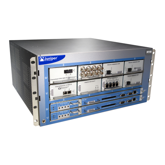
Page 32: Figure 1: Front Of Chassis
Failure to use an ESD strap could result in damage to the router. The router must be connected to earth ground during normal operation. For chassis serial number information , see “Displaying M10i Router Components and Serial Numbers” on page 207. Copyright © 2010, Juniper Networks, Inc. -
Page 33: M10I Midplane Description
Signal connectivity—The midplane transports the signals exchanged by system components for monitoring and control purposes. Figure 3: Midplane For chassis serial number information , see “Displaying M10i Router Components and Serial Numbers” on page 207. Related M10i Chassis Description on page 5... -
Page 34: M10I Flexible Pic Concentrators (Fpcs) Description
FPC1 , which are built in to the chassis. Up to eight PICs install into an M10i router, as shown in Figure 4 on page 9. Four PIC slots are located in each Flexible PIC Concentrator (FPC). The PIC slots on the upper FPC are numbered from (zero/zero) through , right to left. -
Page 35: Figure 4: M10I Pic Location
PIC briefly interrupts forwarding of traffic through the remaining PICs. Most PICs supported on the M10i router have the following components. One or more cable connector ports—Accept a network media connector. LEDs—Indicate PIC and port status. Most PICs have an LED labeled... -
Page 36: M10I Pic Leds
STATUS on the PIC faceplate. Some PICs have additional LEDs, often one per port. The meaning of the LED states differs for various PICs. For more information, see the M10i Multiservice Edge Router PIC Guide. Related M10i PICs Description on page 8... - Page 37 For CFEB or CFEB-E replacement instructions, see “Replacing, Upgrading, or Downgrading an M10i CFEB or CFEB-E” on page 103. The CFEB or CFEB-E communicates with the Routing Engine using a dedicated 100-Mbps Fast Ethernet link that transfers routing table data from the Routing Engine to the forwarding table in the integrated ASIC.
-
Page 38: Cfeb
All manuals and user guides at all-guides.com M10i Multiservice Edge Router Hardware Guide CFEB Figure 5: CFEB The CFEB has the following major components: Processing components: 266-MHz CPU and supporting circuitry Integrated ASIC 33-MHz PCI bus Storage components: 128-MB SDRAM for packet memory... -
Page 39: Cfeb-E
All manuals and user guides at all-guides.com Chapter 2: M10i Hardware Components CFEB-E The CFEB-E provides the following enhanced features: Increased number of logical interfaces. Increased route, nexthop, and interface lookup memory. Increased FPC throughput. Enhanced class of service features, including:... -
Page 40: M10I Cfeb And Cfeb-E Leds
Offline button—Prepares the CFEB-E for removal from the router when pressed. Ejector levers—Control the locking system that secures the CFEB-E in the chassis. Related M10i Packet Forwarding Engine Architecture Overview on page 32 Documentation M10i Routing Engine Description on page 15... -
Page 41: M10I Routing Engine Description
For a description of the Routing Engine's role in router architecture, see “M10i Routing Engine Architecture Overview” on page 33. - Page 42 All manuals and user guides at all-guides.com M10i Multiservice Edge Router Hardware Guide Dual Routing Engines without any high availability features enabled—Traffic is interrupted while the Packet Forwarding Engine is reinitialized. All kernel and forwarding processes are restarted. When the switchover to the new master Routing Engine is complete, routing convergence takes place and traffic is resumed.
-
Page 43: M10I Routing Engine Interface Ports
Chapter 2: M10i Hardware Components NOTE: The first supported release for graceful Routing Engine switchover and nonstop active routing on the M10i router is Junos OS Release 6.1 and Junos OS Release 8.4, respectively. However, for graceful Routing Engine switchover we recommend Junos OS Release 7.0 or later. Graceful restart software requirements are dependent on the routing protocols configured on the router. -
Page 44: M10I Routing Engine 400 Description
All manuals and user guides at all-guides.com M10i Multiservice Edge Router Hardware Guide M10i Routing Engine 400 Description The Routing Engine 400 has the following major components: CPU—Runs Junos OS to maintain the router's routing tables and routing protocols. It has a Pentium-class processor. -
Page 45: M10I Routing Engine 400 Leds
Green On steadily Routing Engine is running normally. ONLINE Related Displaying M10i Router Components and Serial Numbers on page 207 Documentation M10i PIC LEDs on page 10 M10i Router Physical Specifications on page 183 M10i Routing Engine 850 Description Figure 7: Routing Engine The Routing Engine 850 has the following major components (see Figure 7 on page 19): CPU—Runs Junos OS to maintain the router's routing tables and routing protocols. - Page 46 All manuals and user guides at all-guides.com M10i Multiservice Edge Router Hardware Guide CompactFlash card—Provides primary storage. It holds software images, configuration files, and microcode. Hard disk—Provides secondary storage for log files and memory dumps, and can reboot the system if the CompactFlash card fails.
-
Page 47: M10I Routing Engine 850 Leds
On steadily Routing Engine is running normally. ONLINE Related Displaying M10i Router Components and Serial Numbers on page 207 Documentation M10i Router Physical Specifications on page 183 M10i High-Availability Chassis Manager (HCM) Description The High-Availability Chassis Manager (HCM) works with its companion Routing Engine to provide control and monitoring functions for router components. -
Page 48: Figure 8: M10I High-Availability Chassis Manager
PIC removal—If a PIC offline button is pressed, the HCM relays the request to the CFEB or CFEB-E, which takes the PIC offline and informs the Routing Engine. Other PICs are unaffected, and system operation continues. For more information, see “M10i HCM LEDs” on page 23. -
Page 49: M10I Hcm Leds
, right to left. The PIC slots in the lower FPC are numbered from (one/zero) through , right to left. For PIC replacement instructions, see “Replacing an M10i PIC” on page 111. Related M10i HCM Serial Number ID Label on page 209 Documentation... -
Page 50: M10I Power Supplies Overview
The enable pin disables the voltage at the output connector if the power supply is not turned off before removal. Redundant power supplies are hot-removable and hot-insertable, as described in “M10i Field-Replaceable Units (FRUs)” on page 99. Copyright © 2010, Juniper Networks, Inc. -
Page 51: M10I Ac Power Supply Description
Figure 2 on page 6. For information about power supply redundancy and replaceability, see “M10i Power System Description” on page 24. The router must have at least two AC power supplies, and any two AC power supplies can provide full power to the router. -
Page 52: M10I Dc Power Supply Description
M10i Multiservice Edge Router Hardware Guide Figure 11 on page 26 shows the power supply and Table 24 on page 191 lists electrical specifications. For information about the LED, see “M10i Power Supply LEDs” on page 27. Figure 11: AC Power Supply... -
Page 53: M10I Power Supply Leds
Documentation M10i Power System Description on page 24 Replacing an M10i AC Power Supply on page 121 Troubleshooting the M10i Power System When LEDs on All Power Supplies Are Off on page 96 M10i Fan Tray Description The fan trays installed along each side of the chassis draw room air into the chassis to maintain an acceptable operating temperature for the Routing Engine, PICs, CFEB or CFEB-E, and other components. -
Page 54: M10I Cable Management System Description
Figure 13: Airflow Through the Chassis The fan tray is hot-removable and hot-insertable, as described in “M10i Field-Replaceable Units (FRUs)” on page 99. For instructions on replacing it, see “Replacing an M10i Fan Tray” on page 101. CAUTION: Do not remove both fan trays for more than one minute while the router is operating. -
Page 55: Figure 14: Cable Management System
All manuals and user guides at all-guides.com Chapter 2: M10i Hardware Components Figure 14: Cable Management System Related Installing the M10i Cable Management System on page 52 Documentation M10i Chassis Description on page 5 M10i Router Physical Specifications on page 183... - Page 56 All manuals and user guides at all-guides.com M10i Multiservice Edge Router Hardware Guide Copyright © 2010, Juniper Networks, Inc.
-
Page 57: Chapter 3 M10I System Architecture Overview
CHAPTER 3 M10i System Architecture Overview M10i System Architecture Overview on page 31 M10i Packet Forwarding Engine Architecture Overview on page 32 M10i Routing Engine Architecture Overview on page 33 M10i System Architecture Overview The router architecture consists of two major components: Packet Forwarding Engine—Performs Layer 2 and Layer 3 packet switching, route... -
Page 58: M10I Packet Forwarding Engine Architecture Overview
All manuals and user guides at all-guides.com M10i Multiservice Edge Router Hardware Guide M10i Packet Forwarding Engine Architecture Overview The Packet Forwarding Engine performs Layer 2 and Layer 3 packet switching. It can forward up to 15 million packets per second (Mpps) for all packet sizes. The aggregate throughput is 4 gigabits per second (Gbps) full duplex per FPC (8 Gbps full-duplex total throughput rate). -
Page 59: M10I Routing Engine Architecture Overview
M10i Router Physical Specifications on page 183 M10i Routing Engine Architecture Overview The Routing Engine is an Intel-based PCI platform running the Junos OS, which Juniper Networks has developed and optimized to handle large numbers of network interfaces and routes. The software consists of a set of system processes running in protected memory modules on top of an independent operating system. -
Page 60: Routing Engine Functions
All manuals and user guides at all-guides.com M10i Multiservice Edge Router Hardware Guide Figure 17: Routing Engine Architecture Routing Engine Functions The Routing Engine handles all routing protocol processes, as well as the software processes that control the router's interfaces, the chassis components, system management, and user access to the router. -
Page 61: Figure 18: Control Packet Handling For Routing And Forwarding Table
Figure 18: Control Packet Handling for Routing and Forwarding Table Updates Related M10i Routing Engine Description on page 15 Documentation Maintaining the M10i Routing Engine on page 83 Replacing the M10i Routing Engine on page 131 Copyright © 2010, Juniper Networks, Inc. - Page 62 All manuals and user guides at all-guides.com M10i Multiservice Edge Router Hardware Guide Copyright © 2010, Juniper Networks, Inc.
-
Page 63: Part 2 Setting Up The M10I Router
All manuals and user guides at all-guides.com PART 2 Setting Up the M10i Router Preparing the Site for M10i Router Installation on page 39 Overview of M10i Router Installation on page 45 Unpacking the M10i Router on page 47 Installing the M10i Router Mounting Hardware on page 51... - Page 64 All manuals and user guides at all-guides.com M10i Multiservice Edge Router Hardware Guide Copyright © 2010, Juniper Networks, Inc.
-
Page 65: Chapter 4 Preparing The Site For M10I Router Installation
All manuals and user guides at all-guides.com CHAPTER 4 Preparing the Site for M10i Router Installation M10i Router Site Preparation Checklist on page 39 M10i Rack Requirements on page 40 Clearance Requirements for Airflow and Hardware Maintenance on page 43 M10i Router Site Preparation Checklist The checklist in Table 9 on page 39 summarizes the tasks you need to perform when preparing a site for router installation. -
Page 66: M10I Rack Requirements
4-post (telco) racks and open-frame racks. An example of a open-frame rack appears in Figure 19 on page 42. The following sections describe rack requirements: M10i Rack Size and Strength on page 41 Spacing of Mounting Holes on page 42 Connection to Building Structure on page 43... -
Page 67: M10I Rack Size And Strength
All manuals and user guides at all-guides.com Chapter 4: Preparing the Site for M10i Router Installation M10i Rack Size and Strength The router is designed for installation in a 19-in. rack as defined in Cabinets, Racks, Panels, and Associated Equipment (document number EIA-310-D) published by the Electronics Industry Association ( http://www.eia.org... -
Page 68: Spacing Of Mounting Holes
M10i Router Site Preparation Checklist on page 39 Documentation Installing the M10i Router into a Rack on page 55 Installation Safety Warnings for M Series, MX Series, and T Series Routers on page 152 Spacing of Mounting Holes on page 42 Spacing of Mounting Holes The holes in the mounting brackets are spaced at 1 U (1.75 in. -
Page 69: Connection To Building Structure
Related M10i Router Site Preparation Checklist on page 39 Documentation Installing the M10i Router into a Rack on page 55 M10i Rack Size and Strength on page 41 Clearance Requirements for Airflow and Hardware Maintenance When planning the installation site, you must allow sufficient clearance around the rack... -
Page 70: Figure 20: Chassis Dimensions And Clearance Requirements
M10i Router Site Preparation Checklist on page 39 Documentation Installing the M10i Router into a Rack on page 55 Installation Safety Warnings for M Series, MX Series, and T Series Routers on page 152 M10i Rack Size and Strength on page 41... -
Page 71: Overview Of M10I Router Installation
Overview of M10i Router Installation on page 45 Overview of M10i Router Installation After you have verified that your installation site is prepared as described in “M10i Router Site Preparation Checklist” on page 39, you are ready to unpack and install the router. It is important to proceed through the installation process in the following order: Review the safety guidelines explained in “General Safety Guidelines for M Series, MX... - Page 72 All manuals and user guides at all-guides.com M10i Multiservice Edge Router Hardware Guide See “Initially Configuring the M10i Router” on page 73. Connect cables to the PICs. This can be performed either before or after the router is powered on. However, you can check the LEDs after you connect the cables if the router is powered on.
-
Page 73: Chapter 6 Unpacking The M10I Router
This chapter explains how to unpack the router and verify the parts received. It also describes how to move the mounting brackets and install the cable management system. Before beginning, prepare the installation site as described in “M10i Router Site Preparation Checklist” on page 39. This chapter discusses the following topics:... -
Page 74: Verifying The M10I Router Parts Received
Remove the router from the shipping carton. Verify the chassis components received against the packing list included with the router. A generic parts inventory appears in “Verifying the M10i Router Parts Received” on page 48. Save the shipping carton, packing materials, and pallet in case you later need to move or ship the router. -
Page 75: Table 10: Parts List For A Fully Configured Router
Terminal fork lugs, 14-AWG, #6, 0.25 Wide, insulation 9 are shipped, but only up to 8 are strain relieved, for DC power cables used for the M10i router (2 per each power supply) Terminal lugs, 14-AWG, #8 stud, ring tongue, insulated... - Page 76 Ethernet cable, RJ-45/RJ-45, 4-pair stranded UTP, Category 5E, 15' ESD wrist strap with cable Related M10i Router Description on page 3 Documentation M10i Chassis Description on page 5 M10i Router Physical Specifications on page 183 Copyright © 2010, Juniper Networks, Inc.
-
Page 77: Chapter 7 Installing The M10I Router Mounting Hardware
Moving the Mounting Brackets on page 51 Installing the M10i Cable Management System on page 52 Moving the Mounting Brackets The router is shipped with the mounting brackets installed in the front-mounting position, as shown in Figure 1 on page 6. -
Page 78: Installing The M10I Cable Management System
Preventing Electrostatic Discharge Damage to an M10i Router on page 150 Documentation Tools and Parts Required to Install the M10i Router Into a Rack on page 55 Installing the M10i Router into a Rack on page 55 Installation Safety Warnings for M Series, MX Series, and T Series Routers on page 152 Installing the M10i Cable Management System The cable management system organizes and supports the PIC cables to prevent damage. -
Page 79: Figure 23: Installing The Cable Management System
Chapter 7: Installing the M10i Router Mounting Hardware Figure 23: Installing the Cable Management System Related Preventing Electrostatic Discharge Damage to an M10i Router on page 150 Documentation M10i Cable Management System Description on page 28 M10i Chassis Description on page 5... - Page 80 All manuals and user guides at all-guides.com M10i Multiservice Edge Router Hardware Guide Copyright © 2010, Juniper Networks, Inc.
-
Page 81: Chapter 8 Installing The M10I Router
This chapter has the following sections: Tools and Parts Required to Install the M10i Router Into a Rack on page 55 Installing the M10i Router into a Rack on page 55... - Page 82 M10i Multiservice Edge Router Hardware Guide First, perform the following prerequisite procedures: Verify that the router site meets the requirements described in “M10i Router Site Preparation Checklist” on page 39. Place the rack in its permanent location, allowing adequate clearance for airflow and maintenance, and secure it to the building structure.
-
Page 83: Figure 24: Installing The Chassis Into A Open-Frame Rack
All manuals and user guides at all-guides.com Chapter 8: Installing the M10i Router Figure 24: Installing the Chassis into a Open-Frame Rack Copyright © 2010, Juniper Networks, Inc. -
Page 84: Figure 25: Installing The Chassis Into A Four-Post Rack
All manuals and user guides at all-guides.com M10i Multiservice Edge Router Hardware Guide Figure 25: Installing the Chassis into a Four-Post Rack Related M10i Rack Size and Strength on page 41 Documentation M10i Chassis Description on page 5 M10i Chassis Lifting Guidelines on page 151... -
Page 85: Chapter 9 Grounding The M10I Router
Grounding the M10i Router Grounding the M10i Router on page 59 Grounding the M10i Router You must provide the grounding cable. For grounding cable specifications, see “M10i Chassis Grounding Cable and Lug Specifications” on page 187. To connect the grounding cable: Verify that a licensed electrician has attached the two-hole cable lug provided with the router to the grounding cable. -
Page 86: Figure 26: Connecting The Grounding Cable
M10i Multiservice Edge Router Hardware Guide Figure 26: Connecting the Grounding Cable Related Preventing Electrostatic Discharge Damage to an M10i Router on page 150 Documentation M10i Router Site Preparation Checklist on page 39 Connecting Power on an AC-Powered M10i Router on page 65 Connecting Power on an DC-Powered M10i Router on page 67 Copyright ©... -
Page 87: Chapter 10 Connecting The M10I Router To External Devices
Connecting the M10i Router to External Devices Tools and Parts Required to Connect the M10i Router to External Devices on page 61 Connecting to a Management Console or Auxiliary Device on page 62 Connecting to a Network for Out-of-Band Management on page 62... -
Page 88: Connecting To A Management Console Or Auxiliary Device
If you want to connect a device to both ports, you must supply another cable. See “Routing Engine Interface Cable and Wire Specifications for M10i Routers” on page 200. To connect a management console or auxiliary device: Turn off the power to the console or auxiliary device. -
Page 89: Connecting M10I Pic Cables
All manuals and user guides at all-guides.com Chapter 10: Connecting the M10i Router to External Devices Figure 29: Routing Engine Ethernet Cable Connector Figure 30: Routing Engine Management Ports Related M10i Chassis Description on page 5 Documentation M10i Routing Engine 400 Description on page 18... -
Page 90: Figure 31: Attaching Cable To A Pic
Figure 31: Attaching Cable to a PIC Related M10i Chassis Description on page 5 Documentation M10i PICs Description on page 8 M10i Power System Description on page 24 Copyright © 2010, Juniper Networks, Inc. -
Page 91: Chapter 11 Providing Power To The M10I Router
Preventing Electrostatic Discharge Damage to an M10i Router on page 150 Disconnecting Power on an AC-Powered M10i Router on page 67 General Electrical Safety Guidelines and Electrical Codes for M10i Routers on page 167 Copyright © 2010, Juniper Networks, Inc. -
Page 92: Powering On An Ac-Powered M10I Router
NOTE: The Routing Engine boots as the power supply completes its startup sequence. If the Routing Engine finishes booting and you need to power off the router again, see “Powering Off an M10i Router” on page 71. Verify that the... -
Page 93: Disconnecting Power On An Ac-Powered M10I Router
Connect DC power to the router by inserting power cables into the field-wiring terminals on the faceplate of each power supply. DC power cables are not supplied with the router. For information about the required cable type, see “M10i DC Power Cable and Lug Specifications” on page 192. - Page 94 All manuals and user guides at all-guides.com M10i Multiservice Edge Router Hardware Guide NOTE: The router must be connected to at least two separate external DC power sources. CAUTION: There is no standard color coding for DC power cables. The color...
-
Page 95: Powering On A Dc-Powered M10I Router
Preventing Electrostatic Discharge Damage to an M10i Router on page 150 Documentation General Electrical Safety Guidelines and Electrical Codes for M10i Routers on page 167 M10i DC Power Supply Description on page 26 M10i Router DC Power Supply Specifications on page 191... -
Page 96: Disconnecting Power On An Dc-Powered M10I Router
The Routing Engine boots as the power supply completes its startup sequence. If the Routing Engine finishes booting and you need to power off the router again, see “Powering Off an M10i Router” on page 71. After powering on a power supply, wait at least 60 seconds before turning it off. -
Page 97: Powering Off An M10I Router
Preventing Electrostatic Discharge Damage to an M10i Router on page 150 Documentation General Electrical Safety Guidelines and Electrical Codes for M10i Routers on page 167 M10i DC Power Supply Description on page 26 M10i Router DC Power Supply Specifications on page 191... - Page 98 M10i AC Power Supply Description on page 25 Documentation M10i DC Power Supply Description on page 26 Preventing Electrostatic Discharge Damage to an M10i Router on page 150 General Electrical Safety Guidelines and Electrical Codes for M10i Routers on page 167 Copyright © 2010, Juniper Networks, Inc.
-
Page 99: Chapter 12 Configuring Junos Os
To configure the software: Verify that the router is powered on, as described in “Powering On an AC-Powered M10i Router” on page 66 or “Powering On a DC-Powered M10i Router” on page 69. Log in as the root user. There is no password. - Page 100 All manuals and user guides at all-guides.com M10i Multiservice Edge Router Hardware Guide Amnesiac <ttyd0> login: root Start the CLI. root@% cli root> Enter configuration mode. root> configure Entering configuration mode. [edit] root@# Add a password to the root administration user account. Enter a clear-text password.
- Page 101 { authentication-method (password | public-key); name-server { address; interfaces { fxp0 { unit 0 { family inet { address address/prefix-length; Commit the configuration to activate it on the router. [edit] root@# commit Copyright © 2010, Juniper Networks, Inc.
- Page 102 OS displays a message indication this when you log in to the router. Related Configuring CFEB Redundancy on the M10i Router Documentation Configuring the CompactFlash Card on an M10i Routing Engine on page 138 M10i Router Site Preparation Checklist on page 39 Copyright © 2010, Juniper Networks, Inc.
-
Page 103: Part 3 Hardware Maintenance, Troubleshooting, And Replacement Procedures
All manuals and user guides at all-guides.com PART 3 Hardware Maintenance, Troubleshooting, and Replacement Procedures Maintaining M10i Router Hardware Components on page 79 Troubleshooting M10i Hardware Components on page 87 Replacing M10i Hardware Components on page 99 Copyright © 2010, Juniper Networks, Inc. - Page 104 All manuals and user guides at all-guides.com M10i Multiservice Edge Router Hardware Guide Copyright © 2010, Juniper Networks, Inc.
-
Page 105: Chapter 13 Maintaining M10I Router Hardware Components
Components This chapter describes how to maintain hardware components installed in the router. For information about returning a part to Juniper Networks for repair or replacement, see “Contacting Customer Support and Returning M10i Hardware” on page 207. Routine Maintenance Procedures for the M10i Router on page 79... -
Page 106: Maintaining The M10I Cooling System
Related Configuring CFEB Redundancy on the M10i Router Documentation Installing an M10i CFEB or CFEB-E on page 105 M10i CFEB and CFEB-E LEDs on page 14 Troubleshooting the M10i CFEB and CFEB-E on page 90 Maintaining the M10i Cooling System Purpose For optimum cooling, verify the condition of the fans. -
Page 107: Maintaining The M10I Pics And Pic Cables
Check the LEDs on PIC faceplates. The meaning of the LED states differs for various PICs. For more information, see the M10i Multiservice Edge Router PIC Guide. If the FPC that houses the PIC detects a PIC failure, the FPC generates an alarm message to be sent to the Routing Engine. -
Page 108: Maintaining The M10I Power Supplies
Connecting M10i PIC Cables on page 63 Documentation Installing an M10i PIC on page 113 Installing an M10i PIC Cable on page 116 Troubleshooting the M10i PICs on page 94 Replacing an M10i PIC on page 111 Replacing an M10i PIC Cable on page 115... -
Page 109: Maintaining The M10I Routing Engine
LED is lit on the faceplate of both power supplies. OUTPUT OK For more information about the LED, see “M10i Power Supply LEDs” on page 27. Issue the following CLI command to check the status of the power supplies. As shown... - Page 110 Action Check the LEDs on the Routing Engine. The green LED labeled lights steadily ONLINE when it is functioning normally. For more information about the LEDs, see “M10i Routing Engine Description” on page 15. Issue the CLI show chassis routing-engine...
- Page 111 All manuals and user guides at all-guides.com Chapter 13: Maintaining M10i Router Hardware Components Replacing the M10i Routing Engine on page 131 Copyright © 2010, Juniper Networks, Inc.
- Page 112 All manuals and user guides at all-guides.com M10i Multiservice Edge Router Hardware Guide Copyright © 2010, Juniper Networks, Inc.
-
Page 113: Chapter 14 Troubleshooting M10I Hardware Components
The triangular yellow alarm indicates a less severe condition that requires monitoring or maintenance. Both alarms can occur simultaneously. For more information about the alarm LEDs, see “M10i HCM Alarm LEDs” on page 23. Chassis alarms—Indicate a problem with a chassis component such as the cooling system or power supplies. -
Page 114: Troubleshooting The M10I Hcm
Related Displaying M10i Router Components and Serial Numbers on page 207 Documentation M10i Router Physical Specifications on page 183 M10i Routing Engine 400 LEDs on page 19 M10i Routing Engine 850 LEDs on page 21... -
Page 115: Table 13: Routing Engine Alarm Messages
If you are unable to correct the problem, replace the Routing Engine with a spare. For instructions, see “Replacing the M10i Routing Engine” on page 131. If the LED lights correctly on the spare, the original Routing Engine is faulty. Return it to Juniper Networks, as described in “Contacting Customer Support”... -
Page 116: Troubleshooting The M10I Cfeb And Cfeb-E
If you are unable to correct the problem, replace the CFEB or CFEB-E with a spare. For instructions, see “Replacing, Upgrading, or Downgrading an M10i CFEB or CFEB-E” on page 103. If the LED lights correctly on the spare, the original CFEB or CFEB-E is faulty. -
Page 117: Troubleshooting The M10I Fan Tray
If all the LEDs on the HCM are not lit, it might indicate that power is not being provided to the router. See “Troubleshooting the M10i Power System” on page 95. In some cases, the Routing Engine shuts down the router by turning off the power supplies if the temperature passes the acceptable maximum. - Page 118 All manuals and user guides at all-guides.com M10i Multiservice Edge Router Hardware Guide Power Supply 2 Absent Power Supply 3 Absent Temp Intake 25 degrees C / 77 degrees FPC 0 30 degrees C / 86 degrees FPC 1 28 degrees C / 82 degrees...
-
Page 119: Table 15: Cooling System Alarm Messages
If you are unable to correct the problem, replace the fan tray with a spare. For instructions, see “Replacing an M10i Fan Tray” on page 101. If the LED lights correctly on the spare, the original fan tray is faulty. Return it to Juniper Networks for replacement, as described in “Returning a Hardware Component to Juniper Networks,... -
Page 120: Troubleshooting The M10I Pics
If you are unable to correct the problem, replace the PIC with a spare. For instructions, see “Replacing an M10i PIC” on page 111. If the LEDs light correctly on the spare, the original PIC is faulty. Return it to Juniper Networks for replacement, as described in “Contacting Customer Support”... -
Page 121: Troubleshooting The M10I Power System
If any other LED states apply, consult the following topics: Troubleshooting the M10i Power System When LEDs on All Power Supplies Are Off on page 96 Troubleshooting the M10i Power System When the LED on One Power Supply Is Off on page 96 Copyright © 2010, Juniper Networks, Inc. -
Page 122: Troubleshooting The M10I Power System When Leds On All Power Supplies Are Off
Replace the faulty power supply with a spare. For instructions, see “Replacing an M10i AC Power Supply” on page 121 and “Replacing an M10i DC Power Supply” on page 125. If the LED lights correctly on the spare, the original power supply is faulty. Return it to Juniper Networks for replacement, as described in “Returning a Hardware Component... -
Page 123: Table 17: Power System Alarm Messages
Insert or replace operating. secondary power supply. Related M10i AC Power Supply Description on page 25 Documentation M10i DC Power Supply Description on page 26 M10i Power System Description on page 24 M10i Power Supply LEDs on page 27 M10i Router Power Requirements on page 188 Site Electrical Wiring Guidelines for M Series, MX Series, and T Series Routers on page 193 Copyright ©... - Page 124 All manuals and user guides at all-guides.com M10i Multiservice Edge Router Hardware Guide Copyright © 2010, Juniper Networks, Inc.
-
Page 125: Chapter 15 Replacing M10I Hardware Components
Replacing M10i Hardware Components M10i Field-Replaceable Units (FRUs) on page 99 Tools and Parts Required to Replace M10i Hardware Components on page 100 Replacing an M10i Fan Tray on page 101 Replacing, Upgrading, or Downgrading an M10i CFEB or CFEB-E on page 103... -
Page 126: Tools And Parts Required To Replace M10I Hardware Components
General Safety Guidelines for M Series, MX Series, and T Series Routers on page 147 Documentation General Safety Warnings for M Series, MX Series, and T Series Routers on page 148 Guidelines for Packing M10i Components for Shipment on page 215 M10i Router Description on page 3 Contacting Customer Support on page 212... -
Page 127: Replacing An M10I Fan Tray
Routing Engine Rubber safety cap Fiber-optic PIC or PIC cable Related Displaying M10i Router Components and Serial Numbers on page 207 Documentation Guidelines for Packing M10i Components for Shipment on page 215 Contacting Customer Support on page 212 Routine Maintenance Procedures for the M10i Router on page 79 Replacing an M10i Fan Tray The fan trays install into the rear of the chassis, as shown in Figure 2 on page 6. -
Page 128: Installing An M10I Fan Tray
All manuals and user guides at all-guides.com M10i Multiservice Edge Router Hardware Guide CAUTION: To avoid injury, keep tools and your fingers away from the fans as you slide the fan tray out of the chassis. The fans might still be spinning. -
Page 129: Replacing, Upgrading, Or Downgrading An M10I Cfeb Or Cfeb-E
One or two CFEBs or CFEB-Es can install into the uppermost slots in the rear of the chassis, as shown in “M10i Chassis Description” on page 5. Only one CFEB or CFEB-E is active at a time, with the optional second CFEB or CFEB-E in reset mode. CFEBs or CFEB-Es are hot-pluggable when you replace a CFEB with a CFEB or a CFEB-E with a CFEB-E, as described in “M10i Field-Replaceable Units (FRUs)”... -
Page 130: Figure 35: Cfeb
All manuals and user guides at all-guides.com M10i Multiservice Edge Router Hardware Guide Place an electrostatic bag or antistatic mat on a flat, stable surface. Attach an electrostatic discharge (ESD) grounding strap to your bare wrist, and connect the strap to one of the ESD points on the chassis. -
Page 131: Installing An M10I Cfeb Or Cfeb-E
Press the ejector lever at each end of the CFEB or CFEB-E inward. Tighten the thumbscrew on each ejector lever (shown in “M10i CFEB and CFEB-E LEDs” on page 14) to seat the CFEB or CFEB-E firmly in the chassis. -
Page 132: Upgrading Or Downgrading An M10I Cfeb Or Cfeb-E
Replacing an M10i HCM The HCM is hot-pluggable, as described in “M10i Field-Replaceable Units (FRUs)” on page 99. For a description of the effect of removing an HCM, see “M10i Routing Engine Description” on page 15. Removing an M10i HCM on page 106... - Page 133 All manuals and user guides at all-guides.com Chapter 15: Replacing M10i Hardware Components Place an electrostatic bag or antistatic mat on a flat, stable surface. If a Routing Engine is installed in the same row as the HCM you are removing, remove the Routing Engine first.
- Page 134 All manuals and user guides at all-guides.com M10i Multiservice Edge Router Hardware Guide NOTE: Router performance might change if the backup Routing Engine's configuration differs from the former master's configuration. For the most predictable performance, configure the two Routing Engines identically,...
-
Page 135: Installing An M10I Hcm
All manuals and user guides at all-guides.com Chapter 15: Replacing M10i Hardware Components CAUTION: Slide the HCM straight out of the chassis. Damage can result if it gets lodged because of uneven movement. Place one hand under the HCM to support it, slide it completely out of the chassis, and place it on the antistatic mat or in the electrostatic bag. -
Page 136: Figure 40: Installing The Hcm
Figure 40: Installing the HCM Figure 41: Installing a Routing Engine Related M10i HCM LEDs on page 23 Documentation M10i High-Availability Chassis Manager (HCM) Description on page 21 Troubleshooting the M10i HCM on page 88 Copyright © 2010, Juniper Networks, Inc. -
Page 137: Replacing An M10I Pic
Chapter 15: Replacing M10i Hardware Components Replacing an M10i PIC Up to eight regular PICs install into an M10i router, as shown in “M10i Chassis Description” on page 5. Quad-wide PICs occupy all four slots in an FPC row. PICs are hot-removable and hot-insertable. A removed PIC no longer receives or transmits data, and removing or inserting a PIC briefly interrupts forwarding of traffic through the remaining PICs. -
Page 138: Figure 42: Removing A Pic
All manuals and user guides at all-guides.com M10i Multiservice Edge Router Hardware Guide CAUTION: Do not leave a fiber-optic transceiver uncovered except when inserting or removing cable. The safety cap keeps the port clean and prevents accidental exposure to laser light. -
Page 139: Installing An M10I Pic
All manuals and user guides at all-guides.com Chapter 15: Replacing M10i Hardware Components Installing an M10i PIC To install a PIC (see Figure 43 on page 114): Attach an electrostatic discharge (ESD) grounding strap to your bare wrist, and connect the strap to one of the ESD points on the chassis. -
Page 140: Figure 43: Installing A Pic
5 seconds. The LED is usually green; for more information, see the M10i Multiservice Edge Router PIC Guide. The offline button for each PIC is located on the HCM and is labeled with the PIC slot number. -
Page 141: Replacing An M10I Pic Cable
5 seconds. The failure LED is usually red; for more information, see the M10i Multiservice Edge Router PIC Guide. The offline button for each PIC is located on the HCM and is labeled with the PIC slot number. The PICs in FPC... -
Page 142: Installing An M10I Pic Cable
Have ready a length of the type of cable used by the PIC. For cable specifications, see the M10i Multiservice Edge Router PIC Guide. If the PIC cable connector port is covered by a rubber safety plug, remove the plug. -
Page 143: Figure 44: Connecting Fiber-Optic Cable To A Pic
5 seconds. The LED is usually green; for more information, see the M10i Multiservice Edge Router PIC Guide. The offline button for each PIC is located on the HCM and is labeled with the PIC slot number. -
Page 144: Replacing An M10I Sfp
Replacing an M10i SFP Small form-factor pluggables (SFPs) are transceivers that can be removed from a PIC (for more information, see “M10i PICs Description” on page 8). SFPs are hot-insertable and hot-removable. Removing an SFP does not interrupt PIC functioning, but the removed SFP no longer receives or transmits data. -
Page 145: Installing An M10I Sfp
All manuals and user guides at all-guides.com Chapter 15: Replacing M10i Hardware Components the cable management system. Placing fasteners on the loop helps to maintain its shape. Pull the ejector handle away from the SFP faceplate to unseat the SFP from the PIC. -
Page 146: Replacing M10I Power System Components
Verify that the status LEDs on the PIC faceplate indicate that the SFP is functioning correctly (there is an LED for each SFP port). For more information about the PIC LEDs, see the M10i Multiservice Edge Router PIC Guide. You can also verify PIC functioning by issuing the... -
Page 147: Replacing An M10I Ac Power Supply
Installing an M10i AC Power Supply on page 122 Removing an M10i AC Power Supply The AC power supplies are located at the bottom rear of the chassis, as shown in “M10i Chassis Description” on page 5. For information about power supply redundancy and replaceability, see “M10i Power System Description”... -
Page 148: Installing An M10I Ac Power Supply
) position. Locate the AC power cord shipped with the router, which should be appropriate for your geographical location (see “M10i AC Power Cord Specifications” on page 189). Attach an electrostatic discharge (ESD) grounding strap to your bare wrist, and connect the strap to one of the ESD points on the chassis. -
Page 149: Replacing An M10I Ac Power Cord
If the Routing Engine finishes booting and you need to power off the router again, see “Powering Off an M10i Router” on page 71. After a power supply is powered on, it can take up to 60 seconds for status indicators—such as the output status LED on the power supply, the... -
Page 150: Removing An M10I Ac Power Cord
All manuals and user guides at all-guides.com M10i Multiservice Edge Router Hardware Guide Field-Replaceable Units (FRUs)” on page 99. For M10i routers with only two AC power supplies, you must power off the router before replacing an AC power cord. -
Page 151: Replacing An M10I Dc Power Supply
Installing an M10i DC Power Supply on page 126 Removing an M10i DC Power Supply The DC power supplies are located at the bottom rear of the chassis, as shown in “M10i Chassis Description” on page 5. For information about power supply redundancy and replaceability, see “M10i Power System Description”... -
Page 152: Installing An M10I Dc Power Supply
All manuals and user guides at all-guides.com M10i Multiservice Edge Router Hardware Guide Loosen the thumbscrew at each end of the power supply faceplate, using a Phillips screwdriver if necessary. Grasp the handle on the power supply faceplate and pull firmly to slide the unit about halfway out of the chassis. - Page 153 If the Routing Engine finishes booting and you need to power off the router again, see “Powering Off an M10i Router” on page 71. After a power supply is powered on, it can take up to 60 seconds for status indicators—such as the output status LED on the power supply, the...
-
Page 154: Figure 50: Installing A Dc Power Supply
Figure 50: Installing a DC Power Supply Figure 51: Connecting DC power cables to a DC Power Supply Related Preventing Electrostatic Discharge Damage to an M10i Router on page 150 Documentation M10i DC Power Supply Description on page 26 M10i Router Power Requirements on page 188... -
Page 155: Replacing An M10I Dc Power Cable
“M10i Field-Replaceable Units (FRUs)” on page 99. For M10i routers with only two DC power supplies, you must power off the router before replacing the DC power cables. See “Powering Off an M10i Router” on page 71. - Page 156 All manuals and user guides at all-guides.com M10i Multiservice Edge Router Hardware Guide Verify that the power switch on the power supply faceplate is in the ) position. Loop the DC power cables through the hook located on the faceplate to the right of the field-wiring terminals.
-
Page 157: Replacing M10I Routing Engine Components
Replacing M10i Routing Engine Components Replacing the M10i Routing Engine on page 131 Removing and Inserting the PC Card from an M10i Routing Engine on page 135 Replacing the CompactFlash Card in an M10i Routing Engine on page 137 Configuring the CompactFlash Card on an M10i Routing Engine on page 138... -
Page 158: Removing The M10I Routing Engine
All manuals and user guides at all-guides.com M10i Multiservice Edge Router Hardware Guide For detailed information, see “M10i Routing Engine Description” on page 15. To replace a Routing Engine, perform the following procedures: Removing the M10i Routing Engine on page 132... - Page 159 All manuals and user guides at all-guides.com Chapter 15: Replacing M10i Hardware Components If you are removing the master Routing Engine and a second Routing Engine is installed, issue the following CLI command to switch mastership to the backup host module: user@host>...
-
Page 160: Installing The M10I Routing Engine
All manuals and user guides at all-guides.com M10i Multiservice Edge Router Hardware Guide Figure 53: Removing a Routing Engine Installing the M10i Routing Engine To install a Routing Engine (see Figure 54 on page 134): Attach an electrostatic discharge (ESD) grounding strap to your bare wrist, and connect the strap to one of the ESD points on the chassis. -
Page 161: Removing And Inserting The Pc Card From An M10I Routing Engine
Engine. You can also copy Junos OS from the Routing Engine onto a PC Card, for example, to create a backup copy of upgrade software that you have obtained from Juniper Networks. Instructions for copying software to a PC Card are available at the Juniper Networks Support Web site ( http://www.juniper.net/support/... -
Page 162: Inserting The Pc Card In An M10I Routing Engine
Inserting the PC Card in an M10i Routing Engine To insert the PC Card (see Figure 56 on page 136): Orient the PC Card with the Juniper Networks logo facing in the direction specified on the Routing Engine faceplate. Insert the card into the slot. -
Page 163: Replacing The Compactflash Card In An M10I Routing Engine
Attach an electrostatic discharge (ESD) grounding strap to your bare wrist, and connect the strap to one of the ESD points on the chassis. Remove the Routing Engine as described in “Replacing the M10i Routing Engine” on page 131. Use needlenose pliers with grooved jaws to pull the wire clasp out from under the CompactFlash card and lift it up (see Figure 57 on page 137). -
Page 164: Configuring The Compactflash Card On An M10I Routing Engine
To copy software to the CompactFlash card, perform the following procedure: Install the CompactFlash card and replace the Routing Engine as described in“Installing the CompactFlash Card in an M10i Routing Engine” on page 137 and “Installing the M10i Routing Engine” on page 134. -
Page 165: Replacing An Sdram Module On An M10I Routing Engine
Routing Engine. The Routing Engine contains from one to three 168-pin DIMMs. Removing an SDRAM Module from an M10i Routing Engine on page 139 Installing an SDRAM Module in an M10i Routing Engine on page 140 Removing an SDRAM Module from an M10i Routing Engine The SDRAM modules are located on the top of the Routing Engine. -
Page 166: Installing An Sdram Module In An M10I Routing Engine
All manuals and user guides at all-guides.com M10i Multiservice Edge Router Hardware Guide Remove the Routing Engine as described in “Replacing the M10i Routing Engine” on page 131. To release the SDRAM module, press the plastic ejectors on both sides of the module. -
Page 167: Replacing An M10I Ethernet Management Cable
All manuals and user guides at all-guides.com Chapter 15: Replacing M10i Hardware Components Related Preventing Electrostatic Discharge Damage to an M10i Router on page 150 Documentation Installing the M10i Routing Engine on page 134 M10i Routing Engine Architecture Overview on page 33... -
Page 168: Removing An M10I Console Or Auxiliary Cable
All manuals and user guides at all-guides.com M10i Multiservice Edge Router Hardware Guide Figure 62: Console and Auxiliary Ports Removing an M10i Console or Auxiliary Cable on page 142 Installing an M10i Console or Auxiliary Cable on page 142 Removing an M10i Console or Auxiliary Cable... -
Page 169: Appendixes
M10i Router Environmental Specifications on page 185 Power Guidelines, Requirements, and Specifications for the M10i Router on page 187 Cable and Wire Guidelines and Specifications for the M10i Router on page 195 M10i Cable Connector Pinouts on page 201 Contacting Customer Support and Returning M10i Hardware on page 207... - Page 170 All manuals and user guides at all-guides.com M10i Multiservice Edge Router Hardware Guide Copyright © 2010, Juniper Networks, Inc.
-
Page 171: Appendix A Safety And Regulatory Compliance Information For The M10I Router
Preventing Electrostatic Discharge Damage to an M10i Router on page 150 M10i Router Installation Safety Guidelines and Warnings on page 151 Laser and LED Safety Guidelines and Warnings for the M10i Router on page 156 Fire Safety Requirements for M Series, MX Series, and T Series Routers on page 160... - Page 172 All manuals and user guides at all-guides.com M10i Multiservice Edge Router Hardware Guide WARNING: This symbol means danger. You are in a situation that could cause bodily injury. Before you work on any equipment, be aware of the hazards involved with electrical circuitry and be familiar with standard practices for preventing accidents.
-
Page 173: General Safety Guidelines For M Series, Mx Series, And T Series Routers
All manuals and user guides at all-guides.com Appendix A: Safety and Regulatory Compliance Information for the M10i Router Varning! Denna varningssymbol signalerar fara. Du befinner dig i en situation som kan leda till personskada. Innan du utför arbete på någon utrustning måste du vara medveten om farorna med elkretsar och känna till vanligt... -
Page 174: General Safety Warnings For M Series, Mx Series, And T Series Routers
All manuals and user guides at all-guides.com M10i Multiservice Edge Router Hardware Guide Do not push or force any objects through any opening in the chassis frame. Such an action could result in electrical shock or fire. Avoid spilling liquid onto the chassis or onto any router component. Such an action could cause electrical shock or damage the router. -
Page 175: Restricted Access Area Warning
All manuals and user guides at all-guides.com Appendix A: Safety and Regulatory Compliance Information for the M10i Router Restricted Access Area Warning WARNING: The router is intended for installation in restricted access areas. A restricted access area is an area to which access can be gained only by... -
Page 176: Preventing Electrostatic Discharge Damage To An M10I Router
DC Power Electrical Safety Warnings for M Series, MX Series, and T Series Routers on page 174 Preventing Electrostatic Discharge Damage to an M10i Router Many router hardware components are sensitive to damage from static electricity. Some components can be impaired by voltages as low as 30 V. You can easily generate potentially damaging static voltages whenever you handle plastic or foam packing material or if you move components across plastic or carpets. -
Page 177: M10I Router Installation Safety Guidelines And Warnings
The weight of a fully configured chassis is about 79 lb (35.8 kg). Observe the following guidelines for lifting and moving the router: Before moving the router, read the guidelines in “M10i Router Site Preparation Checklist” on page 39 to verify that the intended site meets the specified power, environmental, and clearance requirements. -
Page 178: Installation Safety Warnings For M Series, Mx Series, And T Series Routers
All manuals and user guides at all-guides.com M10i Multiservice Edge Router Hardware Guide Installation Safety Warnings for M Series, MX Series, and T Series Routers Observe the following warnings before and during router installation: Installation Instructions Warning on page 152... - Page 179 All manuals and user guides at all-guides.com Appendix A: Safety and Regulatory Compliance Information for the M10i Router The router must be installed into a rack that is secured to the building structure. The router should be mounted at the bottom of the rack if it is the only unit in the rack.
- Page 180 All manuals and user guides at all-guides.com M10i Multiservice Edge Router Hardware Guide Le rack sur lequel est monté le router doit être fixé à la structure du bâtiment. Si cette unité constitue la seule unité montée en casier, elle doit être placée dans le bas.
- Page 181 All manuals and user guides at all-guides.com Appendix A: Safety and Regulatory Compliance Information for the M10i Router Router må installeres i et stativ som er forankret til bygningsstrukturen. Denne enheten bør monteres nederst i kabinettet hvis dette er den eneste enheten i kabinettet.
-
Page 182: Ramp Warning
Maintenance and Operational Safety Warnings for M Series, MX Series, and T Series Routers on page 161 Laser and LED Safety Guidelines and Warnings for the M10i Router General Laser Safety Guidelines for M10i Routers on page 157 M10i Laser and LED Safety Warnings on page 157... -
Page 183: General Laser Safety Guidelines For M10I Routers
All manuals and user guides at all-guides.com Appendix A: Safety and Regulatory Compliance Information for the M10i Router General Laser Safety Guidelines for M10i Routers Physical Interface Cards (PICs) with single-mode optical interfaces are equipped with laser transmitters, which are considered a Class 1 Laser Product by the U.S. Food and Drug Administration, and are evaluated as a Class 1 Laser Product per EN 60825–1 +A11... -
Page 184: Class 1 Led Product Warning
All manuals and user guides at all-guides.com M10i Multiservice Edge Router Hardware Guide Varning! Laserprodukt av klass 1. Class 1 LED Product Warning WARNING: Class 1 LED product. Waarschuwing Klasse 1 LED-product. Varoitus Luokan 1 valodiodituote. Attention Alarme de produit LED Class I. -
Page 185: Radiation From Open Port Apertures Warning
All manuals and user guides at all-guides.com Appendix A: Safety and Regulatory Compliance Information for the M10i Router ¡Atención! No mirar fijamente el haz ni observarlo directamente con instrumentos ópticos. Varning! Rikta inte blicken in mot strålen och titta inte direkt på den genom optiska instrument. -
Page 186: Fire Safety Requirements For M Series, Mx Series, And T Series Routers
All manuals and user guides at all-guides.com M10i Multiservice Edge Router Hardware Guide Related General Laser Safety Guidelines for M10i Routers on page 157 Documentation Fire Safety Requirements for M Series, MX Series, and T Series Routers General Fire Safety Requirements on page 160... -
Page 187: Maintenance And Operational Safety Warnings For M Series, Mx Series, And T Series Routers
NOTE: To keep warranties effective, do not use a dry chemical fire extinguisher to control a fire at or near a Juniper Networks router. If a dry chemical fire extinguisher is used, the unit is no longer eligible for coverage under a service agreement. -
Page 188: Jewelry Removal Warning
All manuals and user guides at all-guides.com M10i Multiservice Edge Router Hardware Guide recommandée par le fabricant. Jeter les piles usagées conformément aux instructions du fabricant. Warnung Bei Einsetzen einer falschen Batterie besteht Explosionsgefahr. Ersetzen Sie die Batterie nur durch den gleichen oder vom Hersteller empfohlenen Batterietyp. -
Page 189: Lightning Activity Warning
All manuals and user guides at all-guides.com Appendix A: Safety and Regulatory Compliance Information for the M10i Router Attention Avant d'accéder à cet équipement connecté aux lignes électriques, ôter tout bijou (anneaux, colliers et montres compris). Lorsqu'ils sont branchés à l'alimentation et reliés à la terre, les objets métalliques chauffent, ce qui peut provoquer des blessures graves ou souder l'objet métallique aux bornes. -
Page 190: Operating Temperature Warning
All manuals and user guides at all-guides.com M10i Multiservice Edge Router Hardware Guide Varoitus Älä työskentele järjestelmän parissa äläkä yhdistä tai irrota kaapeleita ukkosilmalla. Attention Ne pas travailler sur le système ni brancher ou débrancher les câbles pendant un orage. -
Page 191: Product Disposal Warning
All manuals and user guides at all-guides.com Appendix A: Safety and Regulatory Compliance Information for the M10i Router ο das empfohlene Maximum von 40 C überschreitet. Um Lüftungsverschluß zu verhindern, achten Sie darauf, daß mindestens 15,2 cm lichter Raum um die Lüftungsöffnungen herum frei bleibt. -
Page 192: Electrical Safety Guidelines And Warnings For The M10I Router
If possible, send another person to get medical aid. Otherwise, assess the condition of the victim, then call for help. Related General Electrical Safety Guidelines and Electrical Codes for M10i Routers on page 167 Documentation M10i AC Power Electrical Safety Guidelines on page 172... -
Page 193: Routers
All manuals and user guides at all-guides.com Appendix A: Safety and Regulatory Compliance Information for the M10i Router General Electrical Safety Guidelines and Electrical Codes for M10i Routers Install the router in compliance with the following local, national, or international electrical codes: United States—National Fire Protection Association (NFPA 70), United States... - Page 194 All manuals and user guides at all-guides.com M10i Multiservice Edge Router Hardware Guide Varoitus Tämä laitteisto on tarkoitettu maadoitettavaksi. Varmista, että isäntälaite on yhdistetty maahan normaalikäytön aikana. Attention Cet équipement doit être relié à la terre. S'assurer que l'appareil hôte est relié à la terre lors de l'utilisation normale.
- Page 195 All manuals and user guides at all-guides.com Appendix A: Safety and Regulatory Compliance Information for the M10i Router Advarsel Når enheten installeres, må jordledningen alltid tilkobles først og frakobles sist. Aviso Ao instalar a unidade, a ligação à terra deverá ser sempre a primeira a ser ligada, e a última a ser desligada.
- Page 196 All manuals and user guides at all-guides.com M10i Multiservice Edge Router Hardware Guide Aviso Este dispositivo possui mais do que uma conexão de fonte de alimentação de energia; para poder remover a fonte de alimentação de energia, deverão ser desconectadas todas as conexões existentes.
-
Page 197: Tn Power Warning For M10I Routers
Varning! Enheten är konstruerad för användning tillsammans med elkraftssystem av TN-typ. Related General Electrical Safety Guidelines and Electrical Codes for M10i Routers on page 167 Documentation General Electrical Safety Warnings for M Series, MX Series, and T Series Routers on page 167 Copyright ©... -
Page 198: M10I Ac Power Electrical Safety Guidelines
In Case of an Electrical Accident on page 166 Documentation General Electrical Safety Guidelines and Electrical Codes for M10i Routers on page 167 M10i DC Power Electrical Safety Guidelines on page 173 Japanese AC Power Cord Warning for M Series and MX Series Routers WARNING: Translation from Japanese: The attached power cable is only for this product. -
Page 199: M10I Dc Power Electrical Safety Guidelines And Warnings
All manuals and user guides at all-guides.com Appendix A: Safety and Regulatory Compliance Information for the M10i Router Related Documentation M10i DC Power Electrical Safety Guidelines and Warnings M10i DC Power Electrical Safety Guidelines on page 173 DC Power Electrical Safety Warnings for M Series, MX Series, and T Series... -
Page 200: Dc Power Electrical Safety Warnings For M Series, Mx Series, And T Series Routers
DC Power Electrical Safety Warnings for M Series, MX Series, and T Series Routers on Documentation page 174 DC Power Grounding Requirements and Warning for M10i Routers DC Power Electrical Safety Warnings for M Series, MX Series, and T Series Routers When working with DC-powered equipment, observe the following warnings:... - Page 201 All manuals and user guides at all-guides.com Appendix A: Safety and Regulatory Compliance Information for the M10i Router Waarschuwing Voordat u een van de onderstaande procedures uitvoert, dient u te controleren of de stroom naar het gelijkstroom circuit uitgeschakeld is. Om u ervan te verzekeren dat alle stroom UIT is geschakeld, kiest u op het...
- Page 202 All manuals and user guides at all-guides.com M10i Multiservice Edge Router Hardware Guide y sujetar con cinta la palanca del interruptor automático en posición de Apagado (OFF). Varning! Innan du utför någon av följande procedurer måste du kontrollera att strömförsörjningen till likströmskretsen är bruten. Kontrollera att all strömförsörjning är BRUTEN genom att slå...
-
Page 203: Agency Approvals And Compliance Statements For The M10I Router
All manuals and user guides at all-guides.com Appendix A: Safety and Regulatory Compliance Information for the M10i Router Aviso Quando forem requeridas montagens de instalação eléctrica de cabo torcido, use terminações de cabo aprovadas, tais como, terminações de cabo em circuito fechado e planas com terminais de orelha voltados para cima. - Page 204 Compliance Statements for EMC Requirements for M10i Routers (European Community) on page 180 Compliance Statements for Environmental Requirements for M Series, MX Series, and T Series Routers on page 180 Compliance Statements for Acoustic Noise for M10i Routers on page 181 Copyright © 2010, Juniper Networks, Inc.
-
Page 205: Compliance Statements For Nebs For M Series, Mx Series, And T Series Routers
All manuals and user guides at all-guides.com Appendix A: Safety and Regulatory Compliance Information for the M10i Router Compliance Statements for NEBS for M Series, MX Series, and T Series Routers The equipment is suitable for installation as part of the Common Bonding Network (CBN). -
Page 206: Compliance Statements For Emc Requirements For M10I Routers
Compliance Statements for Environmental Requirements for M Series, MX Series, and T Series Routers on page 180 Compliance Statements for Acoustic Noise for M10i Routers on page 181 Compliance Statements for Environmental Requirements for M Series, MX Series, and T Series Routers Batteries in this product are not based on mercury, lead, or cadmium substances. -
Page 207: Compliance Statements For Acoustic Noise For M10I Routers
All manuals and user guides at all-guides.com Appendix A: Safety and Regulatory Compliance Information for the M10i Router and 98/101/EEC. The product documentation includes instructional information about the proper method of reclamation and recycling. Related General Safety Guidelines for M Series, MX Series, and T Series Routers on page 147... - Page 208 All manuals and user guides at all-guides.com M10i Multiservice Edge Router Hardware Guide Copyright © 2010, Juniper Networks, Inc.
-
Page 209: Appendix B M10I Router Physical Specifications
All manuals and user guides at all-guides.com APPENDIX B M10i Router Physical Specifications M10i Router Physical Specifications on page 183 M10i Router Physical Specifications Table 20 on page 183 summarizes physical specifications for the router chassis. Table 20: M10i Chassis Physical Specifications... - Page 210 All manuals and user guides at all-guides.com M10i Multiservice Edge Router Hardware Guide Copyright © 2010, Juniper Networks, Inc.
-
Page 211: Appendix C M10I Router Environmental Specifications
All manuals and user guides at all-guides.com APPENDIX C M10i Router Environmental Specifications M10i Router Environmental Specifications on page 185 M10i Router Environmental Specifications Table 21 on page 185 specifies the environmental specifications required for normal router operation. In addition, the site should be as dust-free as possible. - Page 212 All manuals and user guides at all-guides.com M10i Multiservice Edge Router Hardware Guide General Safety Guidelines for M Series, MX Series, and T Series Routers on page 147 General Safety Warnings for M Series, MX Series, and T Series Routers on page 148...
-
Page 213: Router
Topics include: M10i Chassis Grounding Cable and Lug Specifications on page 187 M10i Router Power Requirements on page 188 M10i Router AC Power Specifications on page 189... -
Page 214: M10I Router Power Requirements
Table 22 on page 188 lists the power requirements for various hardware components when the router is operating under typical voltage conditions. For PIC power requirements, see the M10i Multiservice Edge Router PIC Guide. Table 22: Component Power Requirements Power Requirement... -
Page 215: M10I Router Ac Power Specifications
All manuals and user guides at all-guides.com Appendix D: Power Guidelines, Requirements, and Specifications for the M10i Router You can use the information in Table 22 on page 188 and the M10i Multiservice Edge Router PIC Guide to calculate power consumption for various hardware configurations, input current from a different source voltage, and thermal output, as shown in the following examples. -
Page 216: Figure 66: Ac Plug Types
All manuals and user guides at all-guides.com M10i Multiservice Edge Router Hardware Guide appliance inlet coupler, type C14 as described by International Electrotechnical Commission (IEC) standard 60320. The plug at the male end of the AC power cord fits into the power source receptacle that is standard for your geographical location. -
Page 217: M10I Router Ac Power Supply Specifications
All manuals and user guides at all-guides.com Appendix D: Power Guidelines, Requirements, and Specifications for the M10i Router Related M10i AC Power Supply Description on page 25 Documentation Connecting Power on an AC-Powered M10i Router on page 65 Replacing an M10i AC Power Supply on page 121... -
Page 218: M10I Dc Power Cable And Lug Specifications
M10i DC Power Supply Description on page 26 Documentation Replacing an M10i DC Power Supply on page 125 Connecting Power on an DC-Powered M10i Router on page 67 M10i Router Power Requirements on page 188 M10i DC Power Cable and Lug Specifications on page 192 M10i DC Power Cable and Lug Specifications You must provide two 14-AWG (2.08 mm... -
Page 219: Site Electrical Wiring Guidelines For M Series, Mx Series, And T Series Routers
All manuals and user guides at all-guides.com Appendix D: Power Guidelines, Requirements, and Specifications for the M10i Router Figure 67: DC Power Cable Connections NOTE: DC power cables must not block access to router components or drape where people could trip on them. - Page 220 Related M10i Router Power Requirements on page 188 Documentation M10i Router AC Power Supply Specifications on page 191 M10i Router DC Power Supply Specifications on page 191 Copyright © 2010, Juniper Networks, Inc.
-
Page 221: Appendix E Cable And Wire Guidelines And Specifications For The M10I Router
Specifications for the M10i Router Network Cable Specifications for M10i Routers on page 195 Routing Engine Interface Cable and Wire Specifications for M10i Routers on page 200 Network Cable Specifications for M10i Routers The various PICs supported on the router accept different kinds of network cable, including multimode and single-mode fiber-optic cable. -
Page 222: Routers
All manuals and user guides at all-guides.com M10i Multiservice Edge Router Hardware Guide Signal Loss in Multimode and Single-Mode Fiber-Optic Cable for M10i Routers Multimode fiber is large enough in diameter to allow rays of light to reflect internally (bounce off the walls of the fiber). Interfaces with multimode optics typically use LEDs as light sources. -
Page 223: Calculating Power Budget For Fiber-Optic Cable For M Series, Mx Series, And T Series Routers
All manuals and user guides at all-guides.com Appendix E: Cable and Wire Guidelines and Specifications for the M10i Router Dispersion is the spreading of the signal in time. The following two types of dispersion can affect an optical data link: Chromatic dispersion—Spreading of the signal in time resulting from the different... -
Page 224: Calculating Power Margin For Fiber-Optic Cable For M Series, Mx Series, And T Series Routers
Fiber-Optic and Network Cable Specifications for M10i Routers on page 195 Documentation Signal Loss in Multimode and Single-Mode Fiber-Optic Cable for M10i Routers on page 196 Attenuation and Dispersion in Fiber-Optic Cable on M Series, MX Series, and T Series... - Page 225 All manuals and user guides at all-guides.com Appendix E: Cable and Wire Guidelines and Specifications for the M10i Router Table 26: Estimated Values for Factors Causing Link Loss (continued) Link-Loss Factor Estimated Link-Loss Value Fiber attenuation Single-mode—0.5 dB/km Multimode—1 dB/km...
-
Page 226: Routing Engine Interface Cable And Wire Specifications For M10I Routers
Routing Engine Interface Cable and Wire Specifications for M10i Routers For management and service operations, you connect the Routing Engine to an external console or management network. (For more information, see “M10i Routing Engine Description” on page 15.) Table 27 on page 200 lists the specifications for the cables that connect to management ports. -
Page 227: Appendix F M10I Cable Connector Pinouts
RJ-45 receptacle that accepts an Ethernet cable for connecting the Routing Engine to a management LAN (or another device that supports out-of-band management). For more information, see “M10i Routing Engine Interface Ports” on page 17. Table 28 on page 201 describes the RJ-45 connector pinout. -
Page 228: Connector Pinouts For The M10I Routing Engine Aux/Modem And Console Ports
CONSOLE management console. The ports are configured as data terminal equipment (DTE). For more information, see “M10i Routing Engine Interface Ports” on page 17. Table 29 on page 202 describes the DB-9 connector pinouts. Table 29: DB-9 Connector Pinout... -
Page 229: Appendix F M10I Cable Connector Pinouts
All manuals and user guides at all-guides.com Appendix F: M10i Cable Connector Pinouts CAUTION: To maintain agency approvals, use only a properly constructed, shielded cable. Table 30 on page 203, Table 31 on page 203, Table 32 on page 204, and Table 33 on page 205 describe the RJ-48 connector pinouts. -
Page 230: Table 32: Rj-48 Connector To Db-15 Connector (Straight) Pinout
All manuals and user guides at all-guides.com M10i Multiservice Edge Router Hardware Guide Table 31: RJ-48 Connector to RJ-48 Connector (Crossover) Pinout (continued) RJ-48 Pin RJ-48 Pin (on T1/E1 PIC) (Data numbering (Data numbering form) form) Signal No connect No connect... -
Page 231: Table 33: Rj-48 Connector To Db-15 Connector (Crossover) Pinout
Documentation M10i PIC LEDs on page 10 Connecting M10i PIC Cables on page 63 Maintaining the M10i PICs and PIC Cables on page 81 Troubleshooting the M10i PICs on page 94 Replacing an M10i PIC on page 111 Copyright © 2010, Juniper Networks, Inc. - Page 232 All manuals and user guides at all-guides.com M10i Multiservice Edge Router Hardware Guide Copyright © 2010, Juniper Networks, Inc.
-
Page 233: Appendix G Contacting Customer Support And Returning M10I Hardware
Contacting Customer Support on page 212 Returning a Hardware Component to Juniper Networks, Inc. on page 213 Tools and Parts Required to Remove Components from an M10i Router on page 214 Packing the M10i Router for Shipment on page 214... -
Page 234: Figure 68: Serial Number Id Label
208) attached to the component body. Figure 68: Serial Number ID Label Related M10i CFEB and CFEB-E Serial Number ID Label on page 209 Documentation M10i HCM Serial Number ID Label on page 209 M10i PIC Serial Number ID Label on page 210... -
Page 235: M10I Cfeb And Cfeb-E Serial Number Id Label
M10i CFEB and CFEB-E LEDs on page 14 Maintaining the M10i CFEB and CFEB-E on page 79 Replacing, Upgrading, or Downgrading an M10i CFEB or CFEB-E on page 103 Contacting Customer Support on page 212 M10i HCM Serial Number ID Label The serial number ID label on an HCM is located near the front on the right side, as shown in Figure 70 on page 210. -
Page 236: M10I Pic Serial Number Id Label
M10i PICs Description on page 8 Documentation M10i PIC LEDs on page 10 Maintaining the M10i PICs and PIC Cables on page 81 Troubleshooting the M10i PICs on page 94 Replacing an M10i PIC on page 111 Contacting Customer Support on page 212... -
Page 237: M10I Power Supply Serial Number Id Label
M10i Power System Description on page 24Replacing an M10i DC Power Supply on Documentation page 125 Troubleshooting the M10i Power System When LEDs on All Power Supplies Are Off on page 96 Troubleshooting the M10i Power System When the LED on One Power Supply Is Off... -
Page 238: Contacting Customer Support
Contacting Customer Support on page 212 Contacting Customer Support You can contact Juniper Networks Technical Assistance Center (JTAC) 24 hours a day, 7 days a week in one of the following ways: On the Web, using the Case Manager link at: http://www.juniper.net/support/... -
Page 239: Returning A Hardware Component To Juniper Networks, Inc
(RMA) is issued. This number is used to track the returned material at the factory and to return repaired or new components to the customer as needed. NOTE: Do not return any component to Juniper Networks, Inc. unless you have first obtained an RMA number. Juniper Networks, Inc. reserves the right to refuse shipments that do not have an RMA. -
Page 240: Tools And Parts Required To Remove Components From An M10I Router
If you do not have these materials, contact your Juniper Networks representative about approved packaging materials. Power off the router. See “Powering Off an M10i Router” on page 71. Attach an electrostatic discharge (ESD) grounding strap to your bare wrist, and connect the strap to one of the ESD points on the chassis. -
Page 241: Guidelines For Packing M10I Components For Shipment
Documentation Returning a Hardware Component to Juniper Networks, Inc. on page 213 Tools and Parts Required to Remove Components from an M10i Router on page 214 Guidelines for Packing M10i Components for Shipment on page 215 Guidelines for Packing M10i Components for Shipment... - Page 242 All manuals and user guides at all-guides.com M10i Multiservice Edge Router Hardware Guide Packing the M10i Router for Shipment on page 214 Copyright © 2010, Juniper Networks, Inc.
-
Page 243: Part 5 Index
All manuals and user guides at all-guides.com PART 5 Index Index on page 219 Copyright © 2010, Juniper Networks, Inc. - Page 244 All manuals and user guides at all-guides.com M10i Multiservice Edge Router Hardware Guide Copyright © 2010, Juniper Networks, Inc.
-
Page 245: Index
............43 brackets path through chassis.............27 angle, in syntax descriptions........xxiii alarm square, in configuration statements.....xxiii LEDs (red and yellow) on HCM.........23 messages, list of.............87 alarms handling by Routing Engine........34 altitude, acceptable range..........185 Copyright © 2010, Juniper Networks, Inc. - Page 246 All manuals and user guides at all-guides.com M10i Multiservice Edge Router Hardware Guide troubleshooting..............90 cable upgrade instructions...........106 auxiliary or console port (for Routing Engine CFEB-E management) ASICs on................10 connecting during initial installation.....62 components..............10 replacing..............141 description (hardware and function).....10 tools required............100 downgrade instructions..........106...
- Page 247 JTAC............xxiv standards.................177 Enhanced Compact Forwarding Engine Board See data flow, through Packet Forwarding Engine.....32 CFEB-E..................10 DB-9 cable connector pinouts (auxiliary and console environmental specifications...........185 ports)..................202 points on chassis..............5 preventing damage to components by....150 Copyright © 2010, Juniper Networks, Inc.
- Page 248 All manuals and user guides at all-guides.com M10i Multiservice Edge Router Hardware Guide Ethernet port (for Routing Engine management) installation instructions..........109 cable LEDs..................23 connection ..............62 alarm (red and yellow)........23 replacement instructions........141 PIC offline buttons............22 specifications............200 removal instructions...........106 tools required............100 routine inspection of.............79 Ethernet port on Routing Engine serial number..............209...
- Page 249 PIC...................8, 10 PC Card Routing Engine..............15 insertion instructions..........136 link loss, calculating.............198 removal instructions............135 lithium battery compliance..........180 physical specifications............183 load sharing (power supplies)...........24 lugs for DC power cables............192 lugs for grounding cables...........187 Copyright © 2010, Juniper Networks, Inc.
- Page 250 All manuals and user guides at all-guides.com M10i Multiservice Edge Router Hardware Guide PIC....................8 power ASIC on.................8 ATM, wavelength range supported.......196 connection instructions during cable replacement............124 installation instructions........116 connection instructions for removal instructions..........115 maintenance............65 tools required............100 disconnection instructions.........67 components..............8, 10 budget calculation............197...
- Page 251 SONET/SDH PIC, wavelength range supported......196 routing SONET/SDH analyzer, use of..........81 table maintenance..........34 specifications serial number..............211 AC power cord...............189 status AC power supply.............25, 191 command for displaying........83 tools required..............100 troubleshooting..............88 Copyright © 2010, Juniper Networks, Inc.
- Page 252 All manuals and user guides at all-guides.com M10i Multiservice Edge Router Hardware Guide cable HCM..................88 DC power ...............192 LEDs grounding..............187 hardware components........87 Routing Engine management ports...200 HCM................87 clearance ................43 overview of tools............87 DC power supply............26, 191 PIC..................94 electrical................189 power system..............95 grounding ...............187...
Need help?
Do you have a question about the M10i and is the answer not in the manual?
Questions and answers