Table of Contents
Advertisement
Quick Links
Advertisement
Table of Contents

Related Manuals for Keithley 7002-HD


Summary of Contents for Keithley 7002-HD
- Page 1 Model 7002-HD High Density Switch System User’s Manual 7002HD-900-01 Rev. A / November 2004 Test Equipment Depot - 800.517.8431 - 99 Washington Street Melrose, MA 02176 - TestEquipmentDepot.com G R E A T E R M E A S U R E...
- Page 2 WARRANTY Keithley Instruments, Inc. warrants this product to be free from defects in material and workmanship for a period of 1 year from date of shipment. Keithley Instruments, Inc. warrants the following items for 90 days from the date of shipment: probes, cables, rechargeable batteries, diskettes, and documentation.
- Page 3 Model 7002-HD High Density Switch System User’s Manual ©2004, Keithley Instruments, Inc. All rights reserved. Cleveland, Ohio, U.S.A. First Printing, November 2004 Document Number: 7002HD-900-01 Rev. A...
- Page 4 Revision includes a revised copy of this print history page. Revision A (Document Number 7002HD-900-01) .............November 2004 All Keithley product names are trademarks or registered trademarks of Keithley Instruments, Inc. Other brand names are trademarks or registered trademarks of their respective holders.
- Page 5 Keithley products are designed for use with electrical signals that are rated Measurement Category I and Measurement Category II, as described in the International Electrotechnical Commission (IEC) Standard IEC 60664. Most measurement, control, and data I/O signals are Measurement Category I and must not be directly connected to mains voltage or to voltage sources with high transient over-voltages.
- Page 6 To maintain protection from electric shock and fire, replacement components in mains circuits, including the power transformer, test leads, and input jacks, must be purchased from Keithley Instruments. Standard fuses, with applicable national safety ap- provals, may be used if the rating and type are the same. Other components that are not safety related may be purchased from other suppliers as long as they are equivalent to the original component.
-
Page 7: Table Of Contents
Table of Contents General Information Introduction ......................Features ......................Warranty information ..................Manual addenda ....................Safety symbols and terms ................Specifications ....................Unpacking and inspection ..................Inspection for damage ..................Shipment contents .................... Manuals ......................Repacking for shipment ................... Optional accessories ....................Installation Introduction ...................... - Page 8 Front Panel Operation Introduction ......................Power-up procedure ....................Line power connections ................... Power switch ....................Power-up sequence ..................Front panel display ....................Vacuum fluorescent display (VFD) ..............Display messages .................... Annunciators ....................Analog backplane ....................Backplane connections ..................Typical backplane .................... Channel assignments ....................
- Page 9 Trigger model ......................Idle and initiate ....................Arm layer1 ....................... Arm layer2 ....................... Trigger layer ..................... Common commands ....................SCPI commands ....................5-11 DISPlay subsystem ..................5-11 ROUTe subsystem ..................5-12 Sense subsystems ................... 5-13 STATus subsystem ..................5-14 SYSTem subsystem ..................5-16 Trigger subsystem ..................
- Page 10 List of Illustrations Installation Figure 2-1 Card installation in Model 7002-HD mainframe ..........Getting Started Figure 3-1 Model 7002-HD front panel ................Figure 3-2 Model 7002-HD rear panel ................. Front Panel Operation Figure 4-1 Model 7002-HD vacuum fluorescent display .............
- Page 11 List of Tables Getting Started Table 3-1 Abbreviated SCPI command summary ............. 3-10 Front Panel Operation Table 4-1 Main MENU structure ..................4-21 Table 4-2 Default conditions ..................... 4-22 Table 4-3 CARD CONFIG MENU structure ..............4-23 Table 4-4 TYPE assignments .................... 4-23 Table 4-5 Scan configuration menu ..................
-
Page 12: General Information
General Information Section 1 topics Introduction, page 1-2 Features, page 1-2 Warranty information, page 1-2 Manual addenda, page 1-2 Safety symbols and terms, page 1-3 Specifications, page 1-3 inspection, page 1-3 Unpacking and Inspection for damage, page 1-3 Shipment contents, page 1-3 Manuals, page 1-4 Repacking for shipment, page 1-4... -
Page 13: Introduction
• Analog Backplane ⎯ Can be used to internally connect the rows or banks of a Model 7002-HD series card installed in one slot to the rows or banks of the Model 7002-HD series cards installed in the other slot. -
Page 14: Safety Symbols And Terms
The following items are included with every order: • Model 7002-HD High Density Switch System • Hard copy of the 7002-HD User’s Manual • PDF copies of the Model 7002-HD User’s and Reference Manuals on CD-ROM • Additional accessories as ordered Return to Section 1 topics... -
Page 15: Manuals
Fill out and include the service form located at the back of this manual. Optional accessories The following accessories are available from Keithley for use with the Model 7002-HD: • Model 7002-HD-MTX1 6 × 32 Differential Matrix Card ⎯ Provides differ- ential matrix switching configured with 6 rows by 32 columns. -
Page 16: Installation
Installation Section 2 topics removal, page 2-2 Card installation and Card installation, page 2-3 Card removal, page 2-3... -
Page 17: Introduction
• Before making or breaking connections, make sure power is removed from all external circuitry. This section includes information on installing cards in the Model 7002-HD High Density Switch System. Card installation and removal The following paragraphs describe how to install and remove cards from the Model 7002-HD mainframe. -
Page 18: Card Installation
Card installation After connecting the input/output cables, perform the following steps, and refer to Figure 2-1 to install the card assembly in the Model 7002-HD mainframe in either the Card 1 or Card 2 location. WARNING Turn off power to all instrumentation (including the Model 7002-HD), and disconnect all line cords. -
Page 19: Figure 2-1 Card Installation In Model 7002-Hd Mainframe
Installation Model 7002-HD User’s Manual Figure 2-1 Card installation in Model 7002-HD mainframe Card Access 7002-HD Screw Cards (2 per card) Return to Section 2 topics... -
Page 20: Getting Started
Getting Started Section 3 topics configurations, page 3-2 Front and rear panel Front panel, page 3-2 Rear panel, page 3-2 assignments, page 3-5 Channel Card 1, page 3-5 Card 2, page 3-5 summary, page 3-6 Front panel operation Create channel list and/or scan list, page 3-6 Close and Open channels, page 3-7... -
Page 21: Introduction
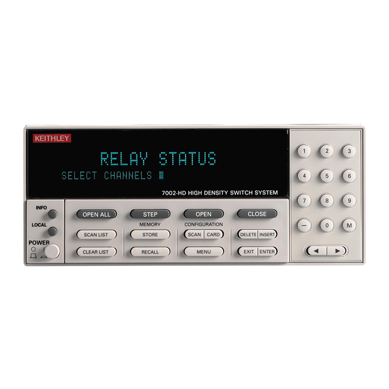
Getting Started Model 7002-HD User’s Manual Introduction This section contains basic information on using the Model 7002-HD including front and rear panel configurations and basic front panel and IEEE-488 bus control. Front and rear panel configurations Front panel The front panel of the Model 7002-HD is shown in Figure 3-1. -
Page 22: Figure 3-1 Model 7002-Hd Front Panel
Enables MAIN MENU: or Scan List. channels, and terminate selected SAVESETUP list. GPIB DIGITAL I/O STEP TEST ˇ akes 7002-HD out of idle state and can be LANGUAGE used to step through the Scan List. GENERAL Return to Section 3 topics... - Page 23 Getting Started Model 7002-HD User’s Manual Figure 3-2 Model 7002-HD rear panel TRIGGER LINK IEEE-488 CARD 1 CARD 2 MADE IN LINE RATING U.S.A. 100-240VAC 50, 60Hz 150VA MAX. 1 CARD 1-2 3 IEEE-488 Connector Use standard IEEE-488 cables. CARD 1= Slots 1-5...
-
Page 24: Channel Assignments
NOTE The specific channel mapping will depend on the particular card being used. Consult the card manual for details. Card 1 When a card is used in the Card 1 position of the Model 7002-HD, it will be con- trolled using slots 1 through 5. Card 2 When a card is used in the Card 2 position of the Model 7002-HD, it will be con- trolled using slots 6 through 10. -
Page 25: Front Panel Operation Summary
WARNING Before turning the Model 7002-HD on, make sure it is con- nected to a grounded power receptacle using the supplied power cord or equivalent. Failure to properly ground the unit creates a shock hazard that could result in injury or death. -
Page 26: Close And Open Channels
Model 7002-HD User’s Manual Getting Started Close and Open channels Press the CLOSE key to close the channels specified in the channel list. Pressing the OPEN key will open the channels specified in the channel list. The OPEN ALL key opens all channels, including any channels not included in the list. - Page 27 Getting Started Model 7002-HD User’s Manual the scan list length as the channel count is appropriate. With manual channel spacing selected, the STEP key is used to manually control the scan. Available channel spacing selections are summarized as follows: TIMER – In general, a channel is scanned each time the programmed timer inter- val expires.
-
Page 28: Ieee-488 Operation Summary
Subsystem commands (:COUNt?, :DELay?, :SOURce?, and :TIMer?). For exam- ple, the :TRIGger:SOURce? query command is used to request the currently selected control source. After the query command is sent and the Model 7002-HD is addressed to talk, a message identifying the selected control source will be sent to the computer. -
Page 29: Table 3-1 Abbreviated Scpi Command Summary
3-10 Getting Started Model 7002-HD User’s Manual Table 3-1 Abbreviated SCPI command summary Command Description :SYSTem Subsystem command path. :PRESet Set scan to a default configuration. [:ROUTe] Subsystem command path. :CLOSe <list> Path and command to close specified channels: :STATe? Request channels that are closed. -
Page 30: Programming Examples
When the above program is run, the scan will arm (ARM indicator on) and then wait for front panel STEP key presses to control the channel scan. After taking the Model 7002-HD out of remote (press LOCAL key), each press of the STEP key will scan the next channel in the scan list. - Page 31 ‘ :TRIG:SOUR TIM Set timer for 0.5 second interval. ‘ :TRIG:TIM Take 7002-HD out of idle state. ‘ :INIT When the above command sequence is run, the scan will arm and scan channels continuously at a 0.5 second rate. Return to...
-
Page 32: Front Panel Operation
Link, page 4-26 Trigger Closing and opening channels, page 4-9 Trigger Link connections, page 4-26 Trigger Link operation, page 4-27 NOTE This section contains basic information on front panel operation. For complete details, see Section 4 of the Model 7002-HD Reference Manual. -
Page 33: Introduction
This section contains basic information on using the Model 7002-HD from the front panel. Power-up procedure The Model 7002-HD can be operated from line voltages from 100-240VAC at line frequencies of 50 or 60Hz. Line power connections Using the supplied power cord, connect the instrument to an appropriate AC power source. -
Page 34: Front Panel Display
The first line can display up to 20 alphanumeric char- acters and the second line can display up to 32 alphanumeric characters. Also included are annunciators that are located along the top of the display. Figure 4-1 Model 7002-HD vacuum fluorescent display Annunciators REM TALK LSTN SRQ... -
Page 35: Display Messages
7002-HD can be placed in the active listener state by addressing it to listen. ARM — Turns on when the Model 7002-HD is taken out of the idle state. A scan can only be performed with the Model 7002-HD out of the idle state. -
Page 36: Analog Backplane
The Model 7002-HD has an analog backplane that allows the rows or multiplexers of a Model 7002-HD series card installed in one card location to be connected to the rows or multiplexers of a 7002-HD series card installed in the other card loca- tion. -
Page 37: Channel Assignments
See the card manual for details on the particular card being used. Channel list and scan list The Model 7002-HD can perform two basic operations: it can close and open a list of channels, and it can scan through a list of channels. The following paragraphs explain how to enter channels for these operations. -
Page 38: Entering Lists
Model 7002-HD User’s Manual Front Panel Operation Entering lists Perform the following steps to create a channel list or scan list using the front panel keys: Step 1: Make sure appropriate list is selected. Open/close operations use the channel list, and scan operations use the scan list. - Page 39 Front Panel Operation Model 7002-HD User’s Manual The hyphen (-) is used to designate a range of channels. After entering the first channel, as explained in Step 2, press the “-” key on the keypad to put in the hyphen, and then key-in the last channel. The following example shows proper for-...
-
Page 40: Closing And Opening Channels
Front Panel Operation Closing and opening channels One of the basic operations of the Model 7002-HD is to close (or open) one or more channels specified by the user. All the specified channels will either close or open at the same time. An exception to this is when the Single Channel mode is enabled. -
Page 41: Scanning Channels
Front Panel Operation Model 7002-HD User’s Manual Scanning channels The Model 7002-HD can scan through a specified list of channels. The order that the channels are presented in the scan list determines the channel order for the scan. Scan process (Trigger Model) The following information describes front panel control of the scan process. -
Page 42: Figure 4-3 Trigger Model (Front Panel Scan Process)
Model 7002-HD User’s Manual Front Panel Operation 4-11 Figure 4-3 Trigger model (front panel scan process) OPEN ALL Idle Idle STEP Another Arm Count Arm Trigger Control = Source (Source Bypass Enabled*) Output Trigger Arm Event Arm Layer Spacing Detection... - Page 43 While in the idle state, the instrument can- not perform a scan. From the front panel, the Model 7002-HD is taken out of the idle state by pressing the STEP key. When not in the idle state (ARM indicator on) the scanning function is considered to be enabled.
-
Page 44: Scan Procedure
Perform the following steps to scan channels: Step 1. Press OPEN ALL. Before configuring a scan, place the Model 7002-HD in the idle state by pressing OPEN ALL. This will stop any scan that is currently in process, open all channels, and place the Model 7002-HD in the idle state. - Page 45 GPIB ⎯ With this selection, bus triggers (GET or *TRG) control chan- nel spacing. Each bus trigger received by the Model 7002-HD will select the next channel of the scan. MANUAL ⎯ With this selection, the front panel STEP key is used to control channel spacing.
- Page 46 Front Panel Operation 4-15 GPIB ⎯ With this selection, bus triggers (GET or *TRG) control scan spacing. A bus trigger received by the Model 7002-HD will allow opera- tion to proceed to the channel layer. MANUAL ⎯ With this selection, the front panel STEP key is used to control scan spacing.
-
Page 47: Scanning Examples
(1 to 9999) to be performed. Step 7. Start the scan Step 1 of this procedure placed the Model 7002-HD in the idle state. In this idle state, a scan cannot be performed. The Model 7002-HD is taken out of the idle state by pressing the STEP key. - Page 48 SCAN SPACING = IMMEDIATE CHANNEL SPACING = TIMER, GPIB, MANUAL, or TRIGLINK Press OPEN ALL to open all channels and place the Model 7002-HD in the idle state. Press STEP to take the 7002-HD out of idle state and operation into the channel layer.
-
Page 49: Channel Patterns (Store And Recall)
4-18 Front Panel Operation Model 7002-HD User’s Manual Press OPEN ALL to open all channels and place the Model 7002-HD in the idle state. Press STEP to take the 7002-HD out of the idle state. The arm spacing event allows operation to pass into the scan layer. -
Page 50: Recalling Channel Patterns
Model 7002-HD User’s Manual Front Panel Operation 4-19 With the cursor on the appropriate selection, press ENTER. One of the fol- lowing typical messages will be displayed: STORE CHANS AT #001 or STORE LIST AT #001 Both messages indicate that storage will occur at memory location 1 (M1). -
Page 51: Menus
(i.e., M10) is scanned, the closed channels in the pattern will remain closed to supply power for the duration of the scan. Menus Using menus Various instrument operations to configure the Model 7002-HD are performed using these menus: • Press the MENU key to access the main menu. -
Page 52: Main Menu
Menu item Description SAVESETUP Setup Menu: SAVE Save setup at a memory location (up to 10). RESTORE Return 7002-HD to setup stored at a memory location. PWRON Power-on Menu: FACTORY DEFAULT Power-on to factory default setup conditions (Table 4-2). USER SETUP Power-on to setup stored at a memory location. -
Page 53: Card Configuration Menu
Card configuration menu Cards can be configured by pressing the CARD CONFIGURATION key. The menu structure is shown and summarized in Table 4-3. Table 4-4 summarizes card types. Most 7002-HD cards do not require manual configuration. NOTE Return to Section 4 topics... -
Page 54: Scan Configuration Menu
Table 4-4 TYPE assignments Assignment message Interpretation* SLOT CARD:7002-HD** 7002-HD series card installed in specified slot. Card 1 slots = 1-5; Card 2 slots = 6-10. For example, 7002-HD-MTX1 will read as “MTX1” card type. SLOT CARD:NONE No card installed in slot, or specified slot is not assigned. - Page 55 4-24 Front Panel Operation Model 7002-HD User’s Manual Table 4-5 Scan configuration menu Menu item Description CHAN-CONTROL Configure Channel Layer: CHANNEL-SPACING Select channel spacing: TIMER Use a timer to select each channel in the scan. EXTERNAL Will be accepted, but no valid hardware exists.
- Page 56 Model 7002-HD User’s Manual Front Panel Operation 4-25 Table 4-5 (cont.) Scan configuration menu Menu item Description ARM-CONTROL Configure Arm Layer: ARM SPACING Select arm spacing control: MANUAL Use STEP key to arm scanner. IMMEDIATE Use to arm scanner immediately.
-
Page 57: Trigger Link
Front Panel Operation Model 7002-HD User’s Manual Trigger Link The Model 7002-HD has enhanced external triggering capabilities using the Trig- ger Link. The Trigger Link has six lines allowing up to six instruments to be con- trolled over this trigger bus. -
Page 58: Trigger Link Operation
(£0.8V) Trigger Link operation In general, Trigger Link input triggers to the Model 7002-HD are used to control scan operation. In order for the Model 7002-HD to respond to Trigger Link compat- ible triggers, the appropriate layers of the scan must be properly programmed. For example, if you want Trigger Link input triggers to control the channel scan pro- cess, you must program Channel Spacing for TRIGLINK trigger events. - Page 59 Model 7002-HD User’s Manual In general, external triggers can be used as events to control scan operation. In order for the Model 7002-HD to respond to external triggers, the appropriate layers of scan operation must be properly configured. ”Scan procedure” on page 4-13 explains how to program the three layers of the scan.
-
Page 60: Figure 4-7 Semi-Synchronous Trigger Link Pulse Specifications
Ten milliseconds after switch closure, the first Model 7002-HD will release the trigger line. However, the second Model 7002-HD will continue to hold the line low since it Return to... - Page 61 Front Panel Operation Model 7002-HD User’s Manual is not finished. Fifty milliseconds after switch closure, the second Model 7002-HD will release the trigger line. The positive-going edge will trigger the meter to per- form a measurement and subsequently pull the trigger line back down to close the next channels.
-
Page 62: Ieee-488 Operation
5-12 Sense subsystems, page 5-13 STATus subsystem, page 5-14 SYSTem subsystem, page 5-16 Trigger subsystem, page 5-16 This section contains only basic information on IEEE-488 NOTE operation. For complete details, see Section 5 of the Model 7002-HD Reference Manual. -
Page 63: Introduction
This section contains basic information on using the Model 7002-HD over the IEEE-488 bus. Remote operations IEEE-488 bus connections The Model 7002-HD can be connected to the IEEE-488 bus through a cable equipped with standard IEEE-488 connectors, an example is shown in Figure 5-1. -
Page 64: Figure 5-2 Ieee-488 Connections
Instrument Instrument Controller Connect the Model 7002-HD to the IEEE-488 bus as follows: Line up the cable connector with the connector located on the rear panel. The connector is designed so that it will fit only one way. Figure 5-3 shows the location of the IEEE-488 connector on the instrument. -
Page 65: Primary Address Selection
IEEE-488 Operation Model 7002-HD User’s Manual Figure 5-3 IEEE-488 connector location TRIGGER LINK IEEE-488 CARD 1 CARD 2 MADE IN LINE RATING U.S.A. 100-240VAC 50, 60Hz 150VA MAX. IEEE-488 Connector Primary address selection The primary address may be set to any value between 0 and 30 as long as address conflicts with other instruments are avoided. -
Page 66: Front Panel Ieee-488 Operation
UNT (Untalk) command, addressing it to listen, or with the IFC (Interface Clear) command. LSTN ⎯ This indicator is on when the Model 7002-HD is in the listener active state, which is activated by addressing the instrument to listen with the correct MLA (My Listen Address) command. -
Page 67: Local Key
Note that the LOCAL key is also inoperative if the LLO (Local Lockout) command is in effect. Trigger model The following information describes the operation process of the Model 7002-HD over the IEEE-488 bus. The flowchart in Figure 5-4, which summarizes operation over the bus, is called the Trigger Model. -
Page 68: Trigger Model (Ieee-488 Bus Operation)
Model 7002-HD User’s Manual IEEE-488 Operation Figure 5-4 Trigger Model (IEEE-488 bus operation) :ABORt *RST :SYST:PRES :INIT :INIT:CONT ON Idle :INIT:CONT ON Initiate :ARM:TCONfigure:DIRection SOURce (Source Bypass Enabled) Another Arm Layer 1 :ARM:COUNt <n> :ARM:IMMediate :ARM:SIGNal (Arm Layer) Output Arm Event... -
Page 69: Idle And Initiate
IEEE-488 Operation Model 7002-HD User’s Manual Idle and initiate The instrument is considered to be in the idle state whenever it is not operating within one of the layers of the Trigger Model. The front panel ARM indicator is off when the instrument is in the idle state. -
Page 70: Common Commands
Model 7002-HD User’s Manual IEEE-488 Operation Common commands Table 5-1 summarizes the common commands used by the Model 7002-HD and are presented in alphabetical order. Table 5-1 IEEE-488.2 common commands and queries Mnemonic Name Description *CLS Clear status Clears all event registers, and Error Queue. - Page 71 Sets the contents of the Service Request Enable enable command Register. *SRE? Service request The Model 7002-HD returns the value of the Ser- enable query vice Request Enable Register. *STB? Read status byte query Returns the value of the Status Byte Register.
-
Page 72: Scpi Commands
Model 7002-HD User’s Manual IEEE-488 Operation 5-11 SCPI commands DISPlay subsystem The display subsystem controls the display circuitry of the Model 7002-HD and is summarized in Table 5-2. Table 5-2 DISPlay command summary Command Description :DISPlay [:WINDow[1]] Path to locate message to top display. -
Page 73: Route Subsystem
5-12 IEEE-488 Operation Model 7002-HD User’s Manual ROUTe subsystem The ROUTe subsystem is used to control signal routing through the switch system and is summarized in Table 5-3. Table 5-3 ROUTe command summary Command Description [:ROUTe] :CLOSe <list> Close specified channels. -
Page 74: Sense Subsystems
Model 7002-HD User’s Manual IEEE-488 Operation 5-13 Table 5-3 (cont.) ROUTe command summary Command Description :MEMory Path to program memory: :SAVE Path to save channel patterns: [:RELays] M<num> Save current channel pattern at specified memory location (1 to 500). :LIST <list>, M<num>... -
Page 75: Status Subsystem
5-14 IEEE-488 Operation Model 7002-HD User’s Manual STATus subsystem The status subsystem is used to control the status registers of the Model 7002-HD. The commands in this subsystem are summarized in Table 5-5. Table 5-5 STATus command summary Command Description... - Page 76 Model 7002-HD User’s Manual IEEE-488 Operation 5-15 Table 5-5 (cont.) STATus command summary Command Description :STATus Path to control trigger event registers: :TRIGger Query event register. [:EVENt]? Program the enable register. :ENABle <NRf> Query enable register. :ENABle? Program the positive transition register.
-
Page 77: System Subsystem
5-16 IEEE-488 Operation Model 7002-HD User’s Manual SYSTem subsystem The system subsystem contains miscellaneous commands and are summarized Table 5-6. Table 5-6 SYSTem command summary Command Description :SYSTem :PRESet Return to :SYST:PRES defaults. :POSetup <name> Select power-on setup: RST, PRESet, SAV0-SAV9. -
Page 78: Trigger Command Summary
Model 7002-HD User’s Manual IEEE-488 Operation 5-17 Table 5-7 Trigger command summary Command Description :INITiate Subsystem command path: [:IMMediate] Initiate one trigger cycle. :CONTinuous <b> Enable (1 or ON) or disable (0 or OFF) continuous initiation of trigger system. :CONTinuous? Query continuous initiation. - Page 79 5-18 IEEE-488 Operation Model 7002-HD User’s Manual Table 5-7 Trigger command summary Command Description :ARM[:SEQuence[1]] :LAYer2 :TCONfigure Path to configure Triggers: :DIRection <name> Enable (SOURce) or disable (ACCeptor) Bypass. :DIRection? Query direction. :ASYNchronous Path to configure asynchronous Trigger Link: :ILINe <NRf>...
-
Page 80: Specifications
Specifications... - Page 81 General SYSTEM DISPLAY: Dual-line vacuum fluorescent. EXPANSION: Two plug-in cards per mainframe. 1st line: 20-character alphanumeric. CARD COMPATIBILITY: Compatible with 7002-HD-MTX1 and 7002-HD- 2nd line: 32-character alphanumeric. MUX1 cards. REAR PANNEL CONNECTORS: MEMORY: Battery backed-up storage for 500 channel patterns.
-
Page 82: Status And Error Messages
Status and Error Messages... -
Page 83: Table B-1 Status And Error Messages
Status and Error Messages Model 7002-HD User’s Manual Table B-1 Status and error messages Code number Description +551 “Incorrect software revision” (EE) +550 “Forbidden channel error” (EE) +530 “Slot 10 identification error” (EE) +529 “Slot 9 identification error” (EE) +528 “Slot 8 identification error”... - Page 84 Model 7002-HD User’s Manual Status and Error Messages Table B-1 (cont.) Status and error messages Code number Description -103 “Invalid Separator” (EE) -104 “Data Type Error” (EE) -105 “GET not allowed” (EE) -108 “Parameter not allowed” (EE) -109 “Missing Parameter” (EE) -110 “Command Header Error”...
- Page 85 Status and Error Messages Model 7002-HD User’s Manual Table B-1 (cont.) Status and error messages Code number Description -201 “Invalid while in local” (EE) -202 “Settings lost due to rtl” (EE) -210 “Trigger error” (EE) -211 “Trigger ignored” (EE) -212 “Arm ignored”...
- Page 86 Index Open Opening channels Optional accessories Output connectors Analog backplane Arm Layer 3-7, 4-12, 4-15, 5-8 Arm layer1 Power-up sequence Arm layer2 Primary address Asynchronous trigger link 4-28 Primary address selection Programming examples 3-11 3-11 Bus connections Rear panel RECALL 4-19 Repacking Card...
- Page 87 Service Form Model No. ______________ Serial No. __________________Date ________________ Name and Telephone No. _________________________________________________ Company ______________________________________________________________ List all control settings, describe problem and check boxes that apply to problem. _________________________ __________________________________________________________________________________________ __________________________________________________________________________________________ ❑ Intermittent ❑ Analog output follows display ❑ Particular range or function bad; specify _______________________________ ❑...
- Page 88 Specifications are subject to change without notice. All Keithley trademarks and trade names are the property of Keithley Instruments, Inc. All other trademarks and trade names are the property of their respective companies. G R E A T E R...
Need help?
Do you have a question about the 7002-HD and is the answer not in the manual?
Questions and answers