
Related Manuals for Keithley 7002


Summary of Contents for Keithley 7002
- Page 1 (217) 352-9330 | Click HERE Find the Keithley 7002 at our website:...
- Page 2 Model 7002 Switch System Quick Reference Guide - Quality Instrumentation ... Guaranteed | (888) 88-SOURCE | www.artis...
- Page 3 Model 7002 Switch System Quick Reference Guide 1993, Keithley Instruments, Inc. All rights reserved. Cleveland, Ohio 44139 U.S.A. Document Number: 7002-903-01 Rev. B / 4-00 - Quality Instrumentation ... Guaranteed | (888) 88-SOURCE | www.artis...
-
Page 4: Table Of Contents
Table of Contents Safety Precautions..............1 Introduction................3 Operation Summary .............4 Menu Structures ..............16 Default Conditions .............21 Error and Status Messages ..........24 Status Registers ..............27 IEEE-488.2 Common Commands ........31 SCPI Command Subsystems ..........33 - Quality Instrumentation ... Guaranteed | (888) 88-SOURCE | www.artis... - Page 5 Safety Precautions The following safety precautions should be observed before using this product and any associated instrumentation. Al- though some instruments and accessories would normally be used with non-hazardous voltages, there are situations where hazardous conditions may be present. This product is intended for use by qualified personnel who recognize shock hazards and are familiar with the safety pre- cautions required to avoid possible injury.
- Page 6 As described in the International Electrotechnical Commis- sion (IEC) Standard IEC 664, digital multimeter measuring circuits (e.g., Keithley Models 175A, 199, 2000, 2001, 2002, and 2010) are Installation Category II. All other instruments’ signal terminals are Installation Category I and must not be connected to mains.
-
Page 7: Safety Precautions
Do not exceed the maximum signal levels of the instruments and accessories, as defined in the specifications and operating information, and as shown on the instrument or test fixture panels, or switching card. When fuses are used in a product, replace with same type and rating for continued protection against fire hazard. - Page 8 Keithley Instruments to maintain accuracy and functionality of the product.) If you are unsure about the applicability of a replacement component, call a Keithley In- struments office for information. To clean an instrument, use a damp cloth or mild, water based cleaner.
-
Page 9: Introduction
Introduction This quick reference guide includes summary information on front panel and IEEE-488 operation for the Model 7002 Switch System. For detailed information, consult the Model 7002 Instruction Manual. All Keithley product names are trademarks or registered trademarks of Keithley Instruments, Inc. -
Page 10: Operation Summary
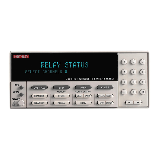
Non-701X series card are not detected by the Model 7002. The model number of each non-701X series card must be assigned to the slot that it is installed in. - Page 11 The light pen is operational when it is plugged into the front panel receptacle labeled LIGHT PEN. Display modes There are two basic display modes for the Model 7002; the relay status display mode and the list display mode. The VFD messages for the display modes are shown as follows:...
- Page 12 List display mode In this display mode, the channel LEDs indicate which channels are included in the selected list (channel list or scan list). Table 1 summarizes the significance of the chan- nel LEDs in this display mode. If you use this display mode when creating a list, be sure to return to the relay status display mode so that you can mon- itor the real-time state (on or off) of each available channel in your switch system.
- Page 13 LED graticule control LED Graticule control allows you to increase contrast between on and off LEDs by eliminating the dimly lit state for LEDs. With the LED Graticule disabled (off), LEDs will be either off or brightly lit. Table 1 explains the significance of the channel LEDs for the two graticule modes.
- Page 14 Table 1: Significance of channel LEDs (cont.) Channel LEDs Display Brightly mode graticule Dimly lit List Channel not Channel Channel available included in included selected in selected list list Channel not — Channel available or included in channel not selected included in list selected list...
- Page 15 Press: MENU Select: SAVESETUP Select: PWRON Select: FACTORY-DEFAULT User Saved Defaults — Up to ten setup configurations can be saved for future recall. The save and restore operations are performed from the SAVESETUP selection in the MAIN MENU as follows: Press: MENU Select:...
- Page 16 X (where X = 0 to 9). Bus Defaults — Over the IEEE-488 bus, the following commands can be used to return the Model 7002 to default conditions: *RST Return 7002 to *RST defaults listed in Table 5.
- Page 17 Channel List Prompt Scan List Prompt SELECT CHANNELS SCAN CHANNELS Channel assignment formats Matrix Card Non-Matrix Card S!R!C S = Slot (1-10) S = Slot (1-10) R = Row (1-4) C = Channel (1-40) C = Column (1-10) Examples: 2!3!6 = Slot 2, Row 3, Column 6 9!38 = Slot 9, Channel 38 Creating a list 1.
- Page 18 Edit Keys and LEDs: Cursor ( ) — Select a channel entry by positioning the cursor on it. DELETE — Press (or click) to delete selected entry. INSERT — Press (or click) INSERT to enable insert func- tion, place cursor at desired location in list and enter chan- nel(s).
- Page 19 Scan List. To perform a scan, first program the control- ling aspects of the scan (see Table 4), and then press (or click) STEP to take the Model 7002 out of the idle state (ARM indicator on). Regardless of how the scan is configured, the STEP key (or LED) is always active allowing you to manually step through the scan.
- Page 20 The scan can be terminated by sending the following com- mand: :ABORt All closed channels will open and the Model 7002 will return to the idle state. Channel patterns (STORE and RECALL) Up to 500 channel patterns can be stored in memory. A channel pattern is simply a pattern of open and closed chan- nels.
- Page 21 Storing the Current List: 1. Create a Channel List. 2. Press STORE and select CURRENT LIST. 3. Key in the memory location (1 to 500) and press ENTER. Recalling a channel pattern: Press RECALL, key in the memory location of the stored channel pattern and press ENTER.
-
Page 22: Menu Structures
Menu item Description SAVESETUP Setup Menu: SAVE Save setup at a memory loca- tion (up to 10). RESTORE Return 7002 to setup stored at a memory location. PWRON Power-on Menu: FACTORY DEFAULT Power-on to factory default setup conditions. USER SETUP Power-on to setup stored at a memory location. - Page 23 PATTERNS Verify operation of VFD display. LED BOARD Verify operation of LED display. CHAR SET Display ASCII character set. LANGUAGE Choose 7002 Language: ENGLISH Display messages in English. GERMAN Display messages in Ger- man. FRENCH Display messages in French. GENERAL...
- Page 24 Table 3. CARD CONFIG MENU structure Menu item Description TYPE Set Card Type: SLOT Assign model number to card in speci- fied slot. #-OF-POLES Select # Of Poles: SLOT Select pole mode for card in specified slot. CARD-PAIR Enable or disable Card Pair. DELAY Set Delay For: SLOT...
- Page 25 Table 4. CONFIGURE SCAN menu structure (cont.) Menu item Description CHAN-CONTROL CHANNEL-SPACING IMMEDIATE Use to scan channels immediately. HOLD Use to hold up the scan in the channel layer. NUMBER-OF-CHANS Define number of chan- nels to scan: USE-SCANLIST-LENGTH Count = number of chan- nel entries in scan list.
- Page 26 Table 4. CONFIGURE SCAN menu structure (cont.) Menu item Description SCAN-CONTROL NUMBER-OF-SCANS Define number of scans to be performed: INFINITE Repeat scan indefinitely. ENTER-SCAN-COUNT Count = user defined value (1 to 9999). CONTROL Select trigger control mode: SOURCE Enable Source Bypass. ACCEPTOR Disable Source Bypass.
-
Page 27: Default Conditions
Default Conditions Table 5. Factory default and RESET defaults Item Factory default RESET Display mode Relay status No change Channel status All open All open Channel list Cleared No change Scan list No change No change GPIB address No change No change Digital I/O output level High... - Page 28 Table 6. *RST and :SYStem:PRESet Defaults :SYSTem: Command name *RST value PRESet value :INITiate :CONTinuous :ARM :SEQuence[1] :LAYer[1] :COUNt :SOURce IMMediate IMMediate :TCONfigure :DIRection ACCeptor ACCeptor :ASYNchronous :ILINe :OLINe :LAYer2 :COUNt INFinite :DELay :SOURce IMMediate IMMediate :TIMer 0.001 0.001 :TCONfigure :DIRection ACCeptor ACCeptor...
- Page 29 Table 6. *RST and :SYStem:PRESet Defaults (cont.) :SYSTem: Command name *RST value PRESet value [:ROUTe] :CONFigure :BBMake :SLOTX where X=1 to 10 :STIMe :CPAirX where X=1 to 5 :SCHannel :DISPlay :SMESsage :WINDow3 :GRATicule - Quality Instrumentation ... Guaranteed | (888) 88-SOURCE | www.artis...
-
Page 30: Error And Status Messages
“Command Error” (EE) -101 “Invalid Character” (EE) -102 “Syntax Error” (EE) Note: Messages associated with light pen operation are located in para- graph 4.5.3 of the Model 7002 Instruction Manual. - Quality Instrumentation ... Guaranteed | (888) 88-SOURCE | www.artis... - Page 31 Table 7. Error and status messages (cont.) Code number Description -103 “Invalid Separator” (EE) -104 “Data Type Error” (EE) -105 “GET not allowed” (EE) -108 “Parameter not allowed” (EE) -109 “Missing Parameter” (EE) -110 “Command Header Error” (EE) -111 “Command Header Separator Error” (EE) -112 “Program mnemonic too long”...
- Page 32 Table 7. Error and status messages (cont.) Code number Description -213 “Init ignored” (EE) -214 “Trigger deadlock” (EE) -215 “Arm deadlock” (EE) -220 “Parameter Error” (EE) -221 “Settings conflict” (EE) -222 “Parameter data out of range” (EE) -223 “Too much data” (EE) -224 “Illegal parameter value”...
-
Page 33: Status Registers
Status Registers Figure 1. Standard event status - Quality Instrumentation ... Guaranteed | (888) 88-SOURCE | www.artis... - Page 34 Figure 2. Operation event status - Quality Instrumentation ... Guaranteed | (888) 88-SOURCE | www.artis...
- Page 35 Chan Questionable Condition Register (B15) (B14 - B10) (B8 - B0) (B9) Chan Questionable Transition Filter (B15) (B14 - B10) (B8 - B0) (B9) Chan Questionable Event Register (B15) (B14 - B10) (B8 - B0) (B9) & & To Questionable Summary Bit (QSB) of Status Byte Register.
- Page 36 Status Summary Messages * STB ? Status Byte Register Serial Poll (B15 - B8) (B7) (B6) (B5) (B4) (B3) (B2) (B1) (B0) & & & & & * SRE Service Request Enable Register (B15 - B8) (B7) (B6) (B5) (B4) (B3) (B2) (B1) (B0)
-
Page 37: Ieee-488.2 Common Commands
IEEE-488.2 Common Commands Table 8. Common commands Mnemonic Name Description *CLS Clear status Clears all event reg- isters and Error Queue. *ESE <NRf> Event status Sets the contents of enable command the Standard Event Status Enable Regis- ter. *ESE? Event status enable Request the pro- query grammed value of... - Page 38 Table 8. Common commands (cont.) Mnemonic Name Description *RCL <NRf> Recall command Returns the Model 7002 to the setup configuration stored in the designated memory location. *RST Reset command Returns the Model 7002 to the *RST default conditions. *SAV <NRf>...
-
Page 39: Scpi Command Subsystems
SCPI Command Subsystems Notes: 1. Brackets ([ ]) are used to denote optional character sets. These optional characters do not have to be included in the program message. Do not use brackets ([ ]) in the program message. 2. Angle brackets (< >) are used to indicate parameter type. - Page 40 Table 9. :DISPlay command summary Command Description :DISPlay [:WINDow[1]] Path to locate message to top display. :TEXT Path to control user text messages. :DATA <a> Define ASCII message “a” using up to 20 characters. :DATA? Query text message. :STATe <b> Enable (1 or ON) or disable (0 or OFF) message mode.
- Page 41 Table 10. :OUTPut command summary Command Description :OUTPut :TTL[1] Path to set polarity of digital output line 1: :LSENse <name> Select polarity; active high (AHIGh) or active low (ALOW). :LSENse? Query polarity of line 1. :TTL2 Path to set polarity of digital output line 2: :LSENse <name>...
- Page 42 Table 11. ROUTe command summary Command Description [:ROUTe] :CLOSe <list> Close specified channels. :STATe? Query list of closed chan- nels. :CLOSe? <list> Query state of specified channels (1 = closed, 0 = open). :OPEN <list>|ALL Open specified (or all) channels. :OPEN? <list>...
- Page 43 Table 11. ROUTe command summary (cont.) Command Description [:ROUTe] :CONFigure :CPAirX <b> Enable (1 or ON) or Dis- able (0 or OFF) Card Pair X (X = [1] to 5). :CPAirX? Query Card Pair X (X = [1] to 5). :SLOTX Path to configure SLOT X (X = [1] to 10):...
- Page 44 Table 12. Sense command summary Command Description :SENSe[1] :TTL[1] Command path to read internal input line. :DATA? Read internal digital input line. :SENSeX Specify slot; X=2 (slot 1) through 11 (slot 10). :DATA? Read digital input for the specified slot. Table 13.
- Page 45 Table 14. :STATus command summary Command Description :STATus :OPERation Path to control operation event registers: [:EVENt]? Query event register. :ENABle <NRf> Program the enable regis- ter. :ENABle? Query enable register. :PTRansition <NRf> Program the positive tran- sition register. :PTRansition? Query positive transition register.
- Page 46 Table 14. :STATus command summary (cont.) Command Description :STATus :OPERation :ARM :SEQuence :PTRansition <NRf> Program the positive transition register. :PTRansition? Query positive transi- tion register. :NTRansition <NRf> Program the negative transition register. :NTRansition? Query negative transi- tion register. :CONDition? Query condition regis- ter.
- Page 47 Table 14. :STATus command summary (cont.) Command Description :STATus :QUEStionable :NTRansition <NRf> Program the negative transition register. :NTRansition? Query the negative transi- tion register. :CONDition? Query the condition regis- ter. :PRESet Return status registers to default states. :QUEue Path to access error queue: [:NEXT]? Query most recent error message.
- Page 48 Table 16. Trigger command summary Command Description :INITiate Subsystem command path: [:IMMediate] Initiate one trigger cycle. :CONTinuous <b> Enable (1 or ON) or disable (0 or OFF) continuous initiation of trigger system. :CONTinuous? Query continuous initiation. :ABORt Reset trigger system. :ARM[:SEQuence[1]] Subsystem command path to configure arm layers:...
- Page 49 Table 16. Trigger command summary (cont.) Command Description :ARM[:SEQuence[1]] :LAYer2 :SOURce? Query control source. :TIMer <n> Set timer interval (0 to 99999.999 sec). :TIMer? Query timer. :SIGNal Loop around control source. :TCONfigure Path to configure Triggers: :DIRection <name> Enable (SOURce) or disable (ACCeptor) Bypass.
- Page 50 Table 16. Trigger command summary (cont.) Command Description :TRIGger[:SEQuence[1]] :TCONfigure Path to configure Triggers: :PROTocol <name> Select protocol: ASYNchro- nous, SSYNchronous. :PROTocol? Query protocol. :DIRection <name> Enable (SOURce) or disable (ACCeptor) Bypass. :DIRection? Query direction. :ASYNchronous Path to configure asynchro- nous Trigger Link: :ILINe <NRf>...
- Page 51 Keithley Instruments, Inc. 28775 Aurora Road Cleveland, Ohio 44139 Printed in the U.S.A. - Quality Instrumentation ... Guaranteed | (888) 88-SOURCE | www.artis...
Need help?
Do you have a question about the 7002 and is the answer not in the manual?
Questions and answers