Beckhoff AG3210 Operating Instructions Manual
Economy planetary gear unit
Hide thumbs
Also See for AG3210:
- Operating instructions manual (54 pages) ,
- Operating instructions manual (66 pages)

Subscribe to Our Youtube Channel
Related Manuals for Beckhoff AG3210


Summary of Contents for Beckhoff AG3210
- Page 1 Operating instructions | EN AG3210 Economy planetary gear unit 29/05/2020 | Version 2.2...
-
Page 3: Table Of Contents
Version numbers............................... 7 Scope of the documentation .......................... 7 Staff qualification............................... 8 Safety and instruction ............................. 10 Explanation of symbols ........................... 10 Beckhoff Services ............................ 12 For your safety.............................. 13 General safety instructions .......................... 13 Product overview............................... 15 Name plate.............................. 16 Type key ................................. - Page 4 Table of content Guidelines and Standards .......................... 62 EU conformity .............................. 62 RoHS ................................ 62 Index ................................... 63 ─── AG3210 Version: 2.2...
-
Page 5: Notes Of The Documentation
Notes of the documentation Disclaimer Beckhoff products are subject to continuous further development. We reserve the right to revise the operating instructions at any time and without prior announcement. No claims for the modification of products that have already been supplied may be made on the basis of the data, diagrams and descriptions in these operating instruc- tions. - Page 6 • Use of untrained personnel • Use of unauthorized spare parts Copyright © Beckhoff Automation GmbH & Co. KG, Germany 1.1.4 The copying, distribution and utilization of this document as well as the communication of its contents to others without express autho- rization is prohibited.
-
Page 7: Version Numbers
Product features Only the product properties specified in the current operating in- structions are valid. Further information given on the product pages of the Beckhoff homepage, in emails or in other publications is not authoritative. Scope of the documen- Apart from these operating instructions, the following documents are... -
Page 8: Staff Qualification
Trained specialists have received specific technical training and have specific technical knowledge and experience. Trained special- ists can: • apply relevant standards and directives • assess tasks that they have been assigned • recognize possible hazards • prepare and set up workplaces ─── AG3210 Version: 2.2... - Page 9 • assess the work environment • independently optimize and carry out their work Customer service Customer service personnel and service personnel are verifiably trained and authorized by Beckhoff or the machine manufacturer for the work on the machine or plant. Version: 2.2 AG3210...
-
Page 10: Safety And Instruction
1.6.1 DANGER Failure to observe will result in serious or fatal injuries. WARNING Failure to observe may result in serious or fatal injuries. CAUTION Failure to observe may result in minor or moderate injuries. ─── AG3210 Version: 2.2... - Page 11 In the case of documentation on a monitor screen, use the zoom function to enlarge the QR code and reduce the distance. Version: 2.2 AG3210 ───...
-
Page 12: Beckhoff Services
Beckhoff and the worldwide partner companies offer comprehensive support and service. Support The Beckhoff Support offers technical advice on the use of individ- ual Beckhoff products and system planning. Staff provide assistance 1.7.1 for programming and commissioning complex automation systems and offer a comprehensive training program. -
Page 13: For Your Safety
Touch electrical components or assemblies only when wearing ESD protective clothing. Move only on a conductive floor. Only use original packaging for further processing When shipping, transporting, storing and packing, use the original packaging or conductive materials. Version: 2.2 AG3210 ───... - Page 14 See chapter: Decommissioning No direct skin contact with solvents or lubricants In case of improper use, the solvents or lubricants used can lead to skin irritations. Therefore, avoid direct skin contact. ─── AG3210 Version: 2.2...
-
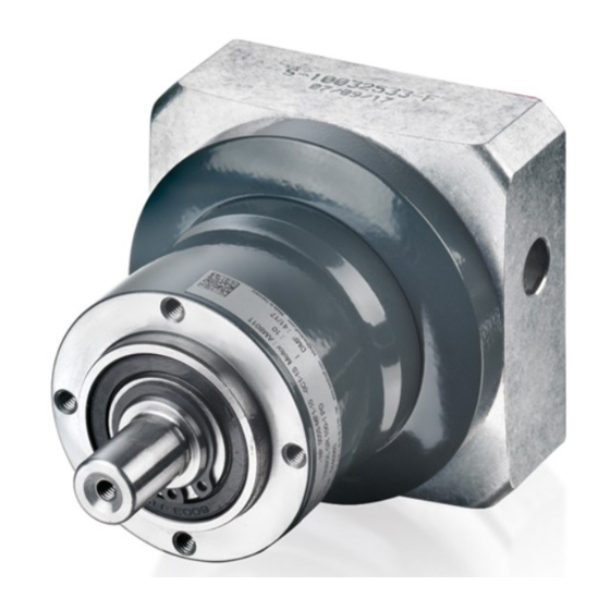
Page 15: Product Overview
Holes for the attachment of the gear unit Feather key [+] Output shaft Clamping hub Holes for the motor attachment Plug; mounting hole Clamping bolt Holes for the motor attachment Holes for the attachment of the gear unit Circlip Adapter plate Version: 2.2 AG3210 ───... -
Page 16: Name Plate
Product overview Name plate Number Explanation Gear unit type Lubrication Combined motor Ratio Data Matrix Code with Beckhoff TN Country of manufacture Date of manufacture Serial number ─── AG3210 Version: 2.2... -
Page 17: Type Key
Product overview Type key AG3210 – NP005S – MF1 – 3 – 1C1 – AM803x Explanation AG3210 Gear unit series AG3210 = NP economy planetary gear unit NP005 Gear type NP 005 NP 015 NP 025 NP 035 NP 045... -
Page 18: Product Characteristics
Maintenance-free ball bearings Due to manufacturing in accordance with the quality standard ISO 9001, the gear units are of a high standard. The ball bearings are lifetime-lubricated and maintenance-free. ─── AG3210 Version: 2.2... -
Page 19: Ordering Options
The listed components cannot be retrofitted. Feather key 3.4.1 3.4.1 A feather key transmits torque to an output element. The gear units are available with feather key groove and inserted feather key according to DIN 6885. Version: 2.2 AG3210 ───... -
Page 20: Intended Use
Any use exceeding the permissible values specified in the Technical data is considered improper and therefore prohibited. 3.5.1 The planetary gear units from the AG3210 series are not suitable for use in the following areas: • ATEX zones without suitable housing •... -
Page 21: Technical Data
(whether at rest or in motion). Running noise L [dB/A] The gear ratio and speed affect the running noise. In general, the following rule applies: • Higher speed = higher running noise • Higher gear ratio = lower running noise Version: 2.2 AG3210 ───... - Page 22 2Emerg The EMERGENCY STOP torque is the maximum permissible torque at the gear unit output. It may be reached one thousand times at the most during the gear unit service life and must never be exceeded. ─── AG3210 Version: 2.2...
-
Page 23: Data For Operation And Environment
Beckhoff products are designed for operation under certain environ- mental conditions, which vary according to the product. The follow- ing specifications must be observed for operation and environment in order to achieve the optimum service life of the products. -
Page 24: Np005
Temperature [°C] Maximum housing temperature + 90 Ambient temperature -15 to + 40 Clamping hub diameter [mm] Standard 8 Z; 9 A; 11 B Large 14 C Housing Properties Anodized; heat-treated steel Color Anthracite gray; RAL 7016 ─── AG3210 Version: 2.2... - Page 25 Temperature [°C] Maximum housing temperature + 90 Ambient temperature -15 to + 40 Clamping hub diameter [mm] Standard 8 Z; 9 A; 11 B Large 14 C Housing Properties Anodized; heat-treated steel Color Anthracite gray; RAL 7016 Version: 2.2 AG3210 ───...
- Page 26 Clamping hub diameter up to 14 mm Check motor shaft adaptation Smallest or largest permissible motor shaft length Dimensions are dependent on the motor Smaller motor shaft diameters are adaptable using a spacer sleeve with a minimum wall thick- ness of 1 mm ─── AG3210 Version: 2.2...
- Page 27 Clamping hub diameter up to 14 mm Check motor shaft adaptation Smallest or largest permissible motor shaft length Dimensions are dependent on the motor Smaller motor shaft diameters are adaptable using a spacer sleeve with a minimum wall thick- ness of 1 mm Version: 2.2 AG3210 ───...
-
Page 28: Np015
Maximum housing temperature + 90 Ambient temperature -15 to + 40 Clamping hub diameter [mm] Standard 9 A; 11 B; 14 C Large 16 D; 19 E Housing Properties Anodized; heat-treated steel Color Anthracite gray; RAL 7016 ─── AG3210 Version: 2.2... - Page 29 Temperature [°C] Maximum housing temperature + 90 Ambient temperature -15 to + 40 Clamping hub diameter [mm] Standard 8 Z; 9 A; 11 B Large 14 C Housing Properties Anodized; heat-treated steel Color Anthracite gray; RAL 7016 Version: 2.2 AG3210 ───...
- Page 30 Clamping hub diameter up to 19 mm Check motor shaft adaptation Smallest or largest permissible motor shaft length Dimensions are dependent on the motor Smaller motor shaft diameters are adaptable using a spacer sleeve with a minimum wall thick- ness of 1 mm ─── AG3210 Version: 2.2...
- Page 31 Clamping hub diameter up to 14 mm Check motor shaft adaptation Smallest or largest permissible motor shaft length Dimensions are dependent on the motor Smaller motor shaft diameters are adaptable using a spacer sleeve with a minimum wall thick- ness of 1 mm Version: 2.2 AG3210 ───...
-
Page 32: Np025
Maximum housing temperature + 90 Ambient temperature -15 to + 40 Clamping hub diameter [mm] Standard 14 C; 16 D; 19 E Large 24 G; 28 H Housing Properties Anodized; heat-treated steel Color Anthracite gray; RAL 7016 ─── AG3210 Version: 2.2... - Page 33 Maximum housing temperature + 90 Ambient temperature -15 to + 40 Clamping hub diameter [mm] Standard 9 A; 11 B; 14 C Large 16 D; 19 E Housing Properties Anodized; heat-treated steel Color Anthracite gray; RAL 7016 Version: 2.2 AG3210 ───...
- Page 34 Clamping hub diameter up to 28 mm Check motor shaft adaptation Smallest or largest permissible motor shaft length Dimensions are dependent on the motor Smaller motor shaft diameters are adaptable using a spacer sleeve with a minimum wall thick- ness of 1 mm ─── AG3210 Version: 2.2...
- Page 35 Clamping hub diameter up to 19 mm Check motor shaft adaptation Smallest or largest permissible motor shaft length Dimensions are dependent on the motor Smaller motor shaft diameters are adaptable using a spacer sleeve with a minimum wall thick- ness of 1 mm Version: 2.2 AG3210 ───...
-
Page 36: Np035
Maximum housing temperature + 90 Ambient temperature -15 to + 40 Clamping hub diameter [mm] Standard 19 E; 24 G; 28 H Large 32 I: 38 K Housing Properties Anodized; heat-treated steel Color Anthracite gray; RAL 7016 ─── AG3210 Version: 2.2... - Page 37 Maximum housing temperature + 90 Ambient temperature -15 to + 40 Clamping hub diameter [mm] Standard 14 C; 16 D; 19 E Large 24 G; 28 H Housing Properties Anodized; heat-treated steel Color Anthracite gray; RAL 7016 Version: 2.2 AG3210 ───...
- Page 38 Clamping hub diameter up to 38 mm Check motor shaft adaptation Smallest or largest permissible motor shaft length Dimensions are dependent on the motor Smaller motor shaft diameters are adaptable using a spacer sleeve with a minimum wall thick- ness of 1 mm ─── AG3210 Version: 2.2...
- Page 39 Clamping hub diameter up to 28 mm Check motor shaft adaptation Smallest or largest permissible motor shaft length Dimensions are dependent on the motor Smaller motor shaft diameters are adaptable using a spacer sleeve with a minimum wall thick- ness of 1 mm Version: 2.2 AG3210 ───...
-
Page 40: Np045
+ 90 Ambient temperature -15 to + 40 Clamping hub diameter [mm] Standard 38 K 19 E; 24 G; 28 H Large 32 I; 38 K Housing Properties Anodized; heat-treated steel Color Anthracite gray; RAL 7016 ─── AG3210 Version: 2.2... - Page 41 Clamping hub diameter up to 38 mm Check motor shaft adaptation Smallest or largest permissible motor shaft length Dimensions are dependent on the motor Smaller motor shaft diameters are adaptable using a spacer sleeve with a minimum wall thick- ness of 1 mm Version: 2.2 AG3210 ───...
- Page 42 Clamping hub diameter up to 38 mm Check motor shaft adaptation Smallest or largest permissible motor shaft length Dimensions are dependent on the motor Smaller motor shaft diameters are adaptable using a spacer sleeve with a minimum wall thick- ness of 1 mm ─── AG3210 Version: 2.2...
-
Page 43: Scope Of Supply
Please check that the delivery includes the following items: • Gear units from the AG3210 series with packaging • Instruction leaflet Screws for fastening the gear unit to the motor or to the machine are not included in the scope of delivery and must be provided by the customer. -
Page 44: Transport And Storage
• Transport and storage only in a horizontal position • Use of the vendor's original packaging Weight The following table shows gear unit masses with a standard adapter flange: 6.1.1 AG3210 NP005 NP015 NP025 NP035 NP045 Single-stage [kg] 18.9 Two-stage [kg] 19.5 If a different adapter flange is used, the weight of the gear unit may differ by up to 30 %. -
Page 45: Transport
Gear unit with motor Transport a motor/gear unit combination as follows: 6.2.2 • using suitable transport slings on the gear unit and on the motor with averaged center of gravity, with sufficiently dimensioned hoists Version: 2.2 AG3210 ───... -
Page 46: Long-Term Storage
Observe the conditions specified in chapter: "Transport and storage", [Page 44]. The gear units are protected against chemical and aggressive sub- stances through the classes 1C2, chemical substances and 1B2, bi- ological conditions. Ensure the storage space is vibration-free. ─── AG3210 Version: 2.2... -
Page 47: Technical Description
Ingress and leakage of liquids may damage the motor. The standard installation position of the gear unit is the motor at- tachment M. Alternatively, it can be used in any other installation po- sition. Version: 2.2 AG3210 ───... -
Page 48: Mechanical Installation
The setting values are rounded to conventional scalings or adjust- ment possibilities: Bolt size Quality of the bolts 10.9 12.9 Tightening torque in Nm 1.15 1.68 1.97 2.64 3.88 4.55 13.2 15.4 21.5 37.5 42.5 62.5 73.5 73.5 1040 ─── AG3210 Version: 2.2... -
Page 49: Motor On Gear Unit
Information on the bolt sizes and tightening torques can be found in the table below: Quality of clamping hub bolt = strength class 12.9 Clamping hub inter- Clamping screw H Width across flats Tightening torque Maximum axial nal diameter [mm] [mm] [Nm] force [N] Version: 2.2 AG3210 ───... - Page 50 ► Remove feather key [+] and insert half wedge ► Remove the plug [1] from the adapter plate [2] ► Rotate the clamping hub [1] until the bolt [2] is visible via the mounting hole ► Loosen the bolt [2] by one turn ─── AG3210 Version: 2.2...
- Page 51 ► Insert bolts [1], [2], [3] and [4] and tighten evenly to 90 % of the yield strength of the bolts. Use bolts of strength class 8.8. ► Tighten bolt [5]. Refer to the chapter "Clamping hub", [Page 49]. ► Insert the plug in the adapter plate again Version: 2.2 AG3210 ───...
-
Page 52: Gear Unit To Machine
Mechanical installation Gear unit to machine No washers necessary Beckhoff recommends not using washers if the material of the screw contact surface has an adequate interface pressure. Output side Avoid damage due to stresses 8.3.1 Use suitable tools for the assembly. Mount gear wheels and toothed belt pulleys without force on the output shaft and avoid mounting by driving or hammering on. - Page 53 Quality of the bolts = strength class 12.9 Gear Pitch circle diame- Thread Tightening torque unit 44 mm 4.55 Nm 62 mm 9.0 Nm 80 mm 15.4 Nm 108 mm 37.5 Nm 140 mm 73.5 Nm Version: 2.2 AG3210 ───...
-
Page 54: Commissioning
In case of motors with holding brake [+] • Check the function of the holding brake [+] • In case of malfunction: Apply 24 VDC, the brake must release • Check emergency stop functions ─── AG3210 Version: 2.2... -
Page 55: During Commissioning
Place the machine or plant in a safe state Make sure that the rotor comes to a complete stop. When the holding brake [+] is released, the rotor moves without remanent torque. Rotating components can lead to serious in- juries. Version: 2.2 AG3210 ───... -
Page 56: Maintenance And Cleaning
For cleaning we have provided you with an overview of cleaning agents to which the motors may be exposed up to a maximum con- centration of 3 %. You will also receive information about non-ap- proved cleaning agents. ─── AG3210 Version: 2.2... - Page 57 NaOH Sodium peroxide Sulfuric acid Tartaric acid COOH; CHOH COOH Tin-II IV-chloride SnCl O SnCl Not applicable Cleaning agents Chemical formula 10.1.2 Aniline hydrochloride Bromine Sodium hypochlorite; bleaching NaCIO solution Mercury (II) chloride HgCl Hydrochloric acid Version: 2.2 AG3210 ───...
-
Page 58: Intervals
Lubrication Notes on lubrication 10.2.1 Beckhoff gear units from the AG3210 series are lubricated for life. The lubricant used does not have to be renewed. If you wish to change the lubricant, contact Beckhoff Service. All gear units are lubricated for life with a lithium soap grease on a mineral oil basis or with a food-safe synthetic lubricating grease con- sisting of hydrocarbon oil and aluminum complex soap. -
Page 59: Fault Correction
Ensure sufficient cooling Replace the motor Ambient temperature too high Ensure sufficient cooling Increased operating noises Distorted motor mounting Contact Beckhoff Service Damage to the bearings Damage to the toothing Toothed belt tension too high Lubricant loss Lubricant quantity too high... -
Page 60: Decommissioning
Leaking oil can cause slips and falls, resulting in serious or fatal injury. Hot oil can cause severe burns. Impermissible removal of gear unit components Only Beckhoff Automation GmbH & Co. KG is permitted to disman- tle the gear unit. Contact Beckhoff Service for further information. -
Page 61: Disposal
The trans- 12.2.1 port costs are borne by the sender. Send the used devices with the note "For disposal" to: Beckhoff Automation GmbH & Co. KG "Service" Building Stahlstrasse 31 D-33415 Verl In addition, you have the option to contact a local certified specialist company for the disposal of used electrical and electronic appli- ances. - Page 62 EU conformity Provision 13.1 Beckhoff Automation GmbH & Co KG will be pleased to provide you with EU declarations of conformity and manufacturer's declara- tions for all products on request. Please send your request to: info@beckhoff.com RoHS All homogeneous materials used in the gear unit fall below the pre- scribed limit values of Directive 2011/65/EU Annex II.
- Page 63 Transport 44 Installation position 47 Instruction 10 Intended use 20 Lubrication 58 Maintenance 56 Intervals 58 Motor Mounting 49 Name plate 16 Operating Conditions 23 Ordering options Feather key 19 Output elements Mounting 52 Pictograms 10 Version: 2.2 AG3210 ───...
- Page 65 More Information: www.beckhoff.com/ag3210 Beckhoff Automation GmbH & Co. KG Hülshorstweg 20 D-33415 Verl Germany Tel: + 49 5246 963-0 info@beckhoff.com www.beckhoff.com...
Need help?
Do you have a question about the AG3210 and is the answer not in the manual?
Questions and answers