Beckhoff AS2000 Series Operating Instructions Manual
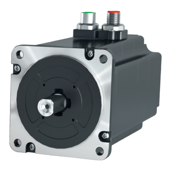
Stepper motor
Hide thumbs
Also See for AS2000 Series:
- Operation manuals (37 pages) ,
- Operating instructions manual (80 pages) ,
- Operating instructions manual (81 pages)
Table of Contents
Advertisement
Advertisement
Table of Contents

Related Manuals for Beckhoff AS2000 Series


Summary of Contents for Beckhoff AS2000 Series
- Page 1 AS2000 Stepper motor Operating instructions | EN 9/10/2019 | Version 2.1...
-
Page 3: Table Of Contents
Version numbers............................... 7 Scope of the documentation .......................... 7 Staff qualification............................... 7 Safety and instruction ............................ 8 Explanation of symbols ............................. 8 Beckhoff Services ............................. 9 For your safety.............................. 10 Safety pictograms ............................ 10 General safety instructions .......................... 11 Product overview............................... 13 Name plate.............................. - Page 4 Table of content Accessories................................ 54 Connection cables ............................ 54 Gear unit ................................. 54 Elastomer coupling ............................ 54 Fault correction.............................. 55 Decommissioning.............................. 57 Disassembly.............................. 57 Disposal ................................ 57 Guidelines and Standards .......................... 58 Standards................................ 58 Guidelines ............................... 58 Test centers .............................. 58 EU conformity ..............................
-
Page 5: Documentation Notes
Documentation notes D o c u m e n t a t i o n n o t e s The documentation has been prepared with care. Beckhoff products Disclaimer are subject to continuous further development. We reserve the right to revise the documentation at any time and without notice. - Page 6 • Improper use • Use of untrained personnel • Use of unauthorized spare parts © Beckhoff Automation GmbH & Co. KG, Germany Copyright The copying, distribution and utilization of this document as well as the communication of its contents to others without express autho- rization is prohibited.
-
Page 7: Version Numbers
The provisions of the accident prevention regulations must be complied with. Customer service Customer service is provided by technicians who have been demonstrably trained and authorized by Beckhoff or the machine manufacturer to work on the respective machine or plant. Version: 2.1 AS2000... -
Page 8: Safety And Instruction
Documentation notes Read the contents, that refer to the activities you have to perform Safety and instruction with the product. Always read the chapter "For your safety", [Page 10] in the operating instructions. Observe the warning notes in the chapters so that you can handle and work properly and safely with the product. -
Page 9: Beckhoff Services
Beckhoff and its international partner companies offer comprehen- Beckhoff Services sive support and service. The Beckhoff Support offers technical advice on the use of individ- Support ual Beckhoff products and system planning. Staff provide assistance for programming and commissioning complex automation systems and offer a comprehensive training program. -
Page 10: For Your Safety
Work particularly thor- oughly, not under time pressure and responsibly towards other peo- ple. On Beckhoff products you will find attached or lasered safety pic- Safety pictograms tograms, which vary depending on the product. They serve to pro- tect people and to prevent damage to the products. -
Page 11: General Safety Instructions
For your safety In this chapter you will find notes on safety when handling the mo- General safety instruc- tors. They cannot run independently. The motors are therefore re- tions garded as incomplete machines. They must be installed in a ma- chine / plant by the machine manufacturer. - Page 12 For your safety Do not work on live electrical parts During operation Do not open the motor while it is live. Ensure that the protective con- ductor is properly connected. Never disconnect electrical connec- tions while they are live. Do not work on the motor until the voltage has dropped below 48 V.
-
Page 13: Product Overview
Product overview P r o d u c t o v e r v i e w A 200 BECKHO Automation GmbH Stepper AS2021 0.8 Nm 24/50 V Number Explanation 1024 Inc Feedback connection Power connection BECKHO Automation GmbH Earth connection Stepper AS2022 1.5 Nm... -
Page 14: Type Key
Stepper motor terminals and stepper motor modules All motors from the AS2000 series are to be put into operation with Beckhoff motor terminals and modules for stepper motors. For fur- ther details at chapter "Electrical installation", [Page 45]. -
Page 15: Ordering Options
Beckhoff stepper motor output stages. The stepper motors from the AS2000 series may be operated exclu- sively for the activities foreseen and defined in this documentation, taking into account the prescribed environmental conditions. -
Page 16: Technical Data
Definitions Characteristic torque and speed curves Detailed information on characteristic curves can be found at: www.beckhoff.de -> Beckhoff motor curves www.beckhoff.de -> TC Motion Designer All data, with the exception of the voltage constant, are based on 40 °C ambient temperature and 100 K overtemperature of the wind- ing. -
Page 17: Data For Operation And Environment
At temperatures above 40 °C and encapsulated installation, the stepper motor may be damaged. Beckhoff products are designed for operation under certain environ- mental conditions, which vary depending on the product. The follow- ing specifications must be observed for operation and environment in order to achieve the optimum service life of the products. -
Page 18: Step Mode And Limit Speeds
Maximum speed of the Beckhoff AS2000 stepper motor The maximum speed is 3600 rpm if using a Beckhoff stepper motor from the AS2000 series with incremental encoder. In practice the maximum speed is limited by the design of the stepper motor. - Page 19 Technical data • All figures in millimeters Dimensional drawing 20,6 Y(Z) ±1,5 4 x Ø4,5 Motor Z - encoder AS2021 64.10 mm 81.10 mm 91.80 mm AS2022 86.20 mm 103.10 mm 113.90 mm AS2023 105.10 mm 122.10 mm 132.80 mm View without encoder 4 x Ø4,5 Version: 2.1 AS2000 ───...
- Page 20 Technical data For the design of your application. The curves were recorded with Characteristic torque and "open loop" controlled operation and "vector control" field-oriented speed curves control. AS2021-0D00 • "Open loop" controlled operation 1000 1200 -0,2 Speed [rpm] Curve Motor type Recording AS2021-0D00 24 V...
- Page 21 Technical data AS2022-0H00 • "Open loop" controlled operation 1000 1200 -0,2 Speed [rpm] Curve Motor type Recording AS2022-0H00 24 V 5.0 A EL7047 AS2022-0H00 48 V 5.0 A EL7047 AS2022-0H00 48 V 5.6 A EL7047+ZB8610 AS2022-0H00 24 V 5.6 A EL7047+ZB8610 AS2022-0H10 • "Vector control" field-oriented control 1000 1200 -0,2 Speed [rpm]...
- Page 22 Technical data AS2023-0H00 • "Open loop" controlled operation 1000 1200 -0,2 Speed [rpm] Curve Motor type Recording AS2023-0H00 48 V 5.0 A EL7047 AS2023-0H00 48 V 5.6 A EL7047+ZB8610 AS2023-0H00 24 V 5.6 A EL7047+ZB8610 AS2023-0H00 24 V 5.0 A EL7047 AS2023-0H10 • "Vector control" field-oriented control 1000 1200 -0,2 Speed [rpm]...
- Page 23 Technical data AS2023-0J00 • "Open loop" controlled operation 1000 1500 2000 Speed [rpm] Curve Motor type Recording AS2023-0J00 24 V 6.4 A EL7047+ZB8610 AS2023-0J00 48 V 6.4 A EL7047+ZB8610 AS2023-0J10 • "Vector control" field-oriented control 1000 1500 2000 -0,2 Speed [rpm] Curve Motor type Recording AS2023-0J10 24 V...
-
Page 24: As204X
Technical data AS204x Electrical data AS2041 AS2042 AS2043 Standstill torque M [Nm] Breakdown torque M [Nm] Rated supply voltage [V 24…50 Rated current [A] Winding resistance Ph-Ph R [Ω] 0.30 0.41 0.38 Winding inductance Ph-Ph L [mH] EtherCAT plug-in module EJ7047 EtherCAT Terminal EL7047 / EL7041-1000... - Page 25 Technical data • All figures in millimeters Dimensional drawing Y(Z) ±1,5 4x Ø5,6 Motor Z - encoder AS2041 71.80 mm 89.30 mm 100.00 mm AS2042 102.25 mm 119.75 mm 130.45 mm AS2043 132.7 mm 150.20 mm 160.90 mm Feather key View without encoder 4x Ø5,6 Version: 2.1 AS2000 ───...
- Page 26 Technical data For the design of your application. The curves were recorded with Characteristic torque and "open loop" controlled operation and "vector control" field-oriented speed curves control AS2041-1H00 • "Open loop" controlled operation 1000 1200 -0,5 Speed [rpm] Curve Motor type Recording AS2041-1H00 24 V...
- Page 27 Technical data AS2041-1H10 • "Vector control" field-oriented control 1000 1200 -0,5 Speed [rpm] Curve Motor type Recording AS2041-1H10 24 V 5.0 A EL7047 AS2041-1H10 24 V 5.6 A EL7047+ZB8610 AS2041-1H10 48 V 5.0 A EL7047 AS2041-1H10 48 V 5.6 A EL7047+ZB8610 Version: 2.1 AS2000 ───...
- Page 28 Technical data AS2042-1H00 • "Open loop" controlled operation 1000 1200 Speed [rpm] Curve Motor type Recording AS2042-1H00 24 V 5.6 A EL7047+ZB8610 AS2042-1H00 24 V 5.0 A EL7047 AS2042-1H00 48 V 5.6 A EL7047+ZB8610 AS2042-1H00 48 V 5.0 A EL7047 AS2042-1H10 • "Open loop" controlled operation 1000 1200 Speed [rpm] Curve Motor type...
- Page 29 Technical data AS2042-1H10 • "Vector control" field-oriented control 1000 1200 Speed [rpm] Curve Motor type Recording AS2042-1H10 24 V 5.0 A EL7047 AS2042-1H10 24 V 5.6 A EL7047+ZB8610 AS2042-1H10 48 V 5.0 A EL7047 AS2042-1H10 48 V 5.6 A EL7047+ZB8610 Version: 2.1 AS2000 ───...
- Page 30 Technical data AS2043-1J00 • "Open loop" controlled operation 1000 1200 Speed [rpm] Curve Motor type Recording AS2043-1J00 24 V 6.5 A EL7047+ZB8610 AS2043-1J00 24 V 5.0 A EL7047 AS2043-1J00 48 V 5.0 A EL7047 AS2043-1J00 48 V 6.5 A EL7047+ZB8610 AS2043-1J10 • "Open loop" controlled operation 1000 1200 Speed [rpm] Curve Motor type...
- Page 31 Technical data AS2043-1J10 • "Vector control" field-oriented control 1000 1200 Speed [rpm] Curve Motor type Recording AS2043-1J10 24 V 5.0 A EL7047 AS2043-1J10 24 V 6.5 A EL7047+ZB8610 AS2043-1J10 48 V 5.0 A EL7047 AS2043-1J10 48 V 6.5 A EL7047+ZB8610 Version: 2.1 AS2000 ───...
-
Page 32: Elastomer Coupling [+]
Technical data • All details on dimensional drawings in millimeters Elastomer coupling [+] AX2090-+EC05 Mechanical data AX2090-+EC05-c/d Motor shaft diameter c / output shaft diameter d 6.35 / 6.00 6.35 / 6.35 6.35 / 8.0 Shore hardness of elastomer ring [Sh] Proportionate attenuation [ψ] 0.4 to 0.5 Rated torque T... - Page 33 Technical data 6.35 / 6.35 • Motor shaft diameter / output shaft diameter 16.7 Ø6.35 H7 Ø6.35 H7 6.00 / 8.00 • Motor shaft diameter / output shaft diameter 16.7 Ø8 H7 Ø6.35 H7 Version: 2.1 AS2000 ───...
- Page 34 Technical data 4.6.2 AX2090-+EC10 Mechanical data AX2090-+EC10-c/d Motor shaft diameter c / output shaft diameter d 14.00 / 14.00 14.00 / 16.00 Shore hardness of elastomer ring [Sh] Proportionate attenuation [ψ] 0.4 to 0.5 Rated torque T [Nm] 12.5 Max. torque T [Nm] KMAX Spacing distance A [mm]...
- Page 35 Technical data 14.00 / 16.00 • Motor shaft diameter / output shaft diameter 10.5 20.7 10.5 Ø16 H7 Ø14 H7 10.3 10.3 Version: 2.1 AS2000 ───...
-
Page 36: Scope Of Supply
Please check that the delivery includes the following items: • Motor from the AS2000 series with yellow protective cap • Instruction leaflet for brief information Instructions for handling are printed on the packaging:... -
Page 37: Transport And Storage
Transport and storage T r a n s p o r t a n d s t o r a g e Avoid damage to the motors and resulting loss of warranty Observe the conditions and the following chapters on transport and storage. -
Page 38: Transport
Transport and storage Transport Do not enter the area below suspended motors Use suitable means of transport and secure the motor against fall- ing. Dropping the motor could lead to fatal accidents. Avoid hard impacts on the motor Use suitable means of transport and secure the motor against fall- ing. -
Page 39: Technical Description
Technical description T e c h n i c a l d e s c r i p t i o n The standard installation position of the motors is the design IM B5 Mounting position according to DIN 60034-7. IM V1 (V1) IM V3 (V3) IM B5 (B5) -
Page 40: Mechanical Installation
Mechanical installation M e c h a n i c a l i n s t a l l a t i o n Perform all work with the greatest care and without hurrying. The following table provides information on components for mount- Flange mounting ing the motor on the machine / system: Motor... - Page 41 Mechanical installation Mounting Do not touch hot output elements without personal protective equipment Only handle hot output elements, such as couplings or pulleys, with special thermal gloves. Avoid prolonged contact with hot com- ponents. Hot components can cause severe burns to body parts and limbs. Do not mount the drive element offset Place the drive elements centered and straight on the motor shaft.
- Page 42 Mechanical installation Use only backlash-free and friction-locked collets, gear pullers or Dismantling suitable couplings to dismount the output elements. ► Degrease the motor shaft ► Screw puller 3 and intermediate disc 2 into the locking thread of the motor shaft ►...
-
Page 43: Elastomer Coupling [+]
Facilitated assembly The bores in the coupling hub have an H7 fit. Beckhoff recommends play of 0.1 – 0.5 mm between the coupling hub and the shaft. The fitting tolerance and the oiling of the shaft journals simplify the assembly and disassembly of the coupling. - Page 44 Adhere to the concentricity and axial run-out accuracies and do not clamp to the hub bridges. For customer-specific special solutions and changes to the coupling hubs, contact our Applications Department. Beckhoff GmbH & Co. KG accepts no liability for unapproved, unauthorized conversions and modifications of the components.
-
Page 45: Electrical Installation
Beckhoff supplies prefabricated power and feedback cables. Mating connectors are not included in the scope of supply. For the selection of the necessary cables, refer to the Beckhoff documentation for the connecting cables [+]. In the documentation you will find a complete overview of the available cables and information on the technical data. - Page 46 Electrical installation Power ► Make sure that the poles and the interior of the socket as well as the threads on the connector are not dirty or damaged ► Push connector 1 straight onto socket 2 on the motor ► Screw thread 3 into the socket The stepper motors are marked on the housing with the symbol for Connection of the protec- protective earth.
- Page 47 Electrical installation • For AS2021-0Dy0 with encoder for field-oriented control EL7037 terminal • The ZB8610 fan cartridge is required to achieve the full rated motor power Motor cable • Order key: ZK4000-7700-xxxx • Preassembled at both ends and shielded: 4 x 0.75 mm² Encoder cable •...
- Page 48 Electrical installation • For AS2022-0Hy0, AS2023-0Hy0, AS2041-1Hy0, AS20421Hy0 EL7047 terminal and AS2043-1Jy0 with encoder for field-oriented control • The ZB8610 fan cartridge is required to achieve the full rated motor power Motor cable • Order key: ZK4000-7700-xxxx • Preassembled at both ends and shielded: 4 x 0.75 mm² Encoder cable •...
- Page 49 Electrical installation • For AS2021-0Dy0 with encoder for high-speed applications EP7041 stepper motor module Motor cable • Order key: ZK4000-6877-xxxx • Preassembled at both ends and shielded: 4 x 0.75 mm² Encoder cable • Order key: ZK4000-5151-0xxx • Preassembled at both ends and shielded: 5 x 0.35 mm² Version: 2.1 AS2000 ───...
-
Page 50: Commissioning
• Check protective measures against moving and live parts Configuration Beckhoff recommends the use of stepper motor terminals and mo- tors from Beckhoff in combinations and configuration in the Beckhoff TwinCAT DriveManager. Carry out the operating procedures in the operating instructions for stepper motor terminals: •... -
Page 51: Prerequisites During Operation
Commissioning • Pay attention to atypical noise development Prerequisites during op- • Pay attention to smoke development eration • Always check drive surfaces and lines for dirt, leakages, mois- ture or dust • Check temperature development • Check for lubricant leakage •... -
Page 52: Maintenance And Cleaning
Maintenance and cleaning M a i n t e n a n c e a n d c l e a n i n g Ensure safe condition for cleaning work Basically, electronic devices are not fail-safe. The condition is al- ways safe when the unit is switched off and not energized. -
Page 53: Intervals
Maintenance and cleaning Under nominal conditions, the motor components have different op- Intervals erating hours. We have provided you with a list of maintenance work and intervals for the associated components below: Component Interval Maintenance Ball bearing 30000 operating hours Replace bearing Motor 2500 operating hours / annually... -
Page 54: Accessories
[Page 14]. 12.3 Elastomer coupling You have the possibility to use the Beckhoff elastomer coupling for applications that are susceptible to vibrations and impacts. The elas- tomer ring between the coupling hubs has damping properties. Lateral, axial and angular shaft offsets can be compensated with the elastomer coupling. -
Page 55: Fault Correction
Fault correction F a u l t c o r r e c t i o n The following table describes only a selection of faults. There can be a large number of different reasons for a fault, depending on the particular conditions in your system. - Page 56 Feedback connector not fitted correctly Check the position of the feedback connector Loose fit of the feedback connector or no contact of the plug Check the connector assembly. Contact Beckhoff Service if contacts with the power socket of the motor. necessary ───...
-
Page 57: Decommissioning
Hot oil can cause severe burns. Impermissible removal of motor components The motors have permanent magnets in the rotor. These motors may only be dismantled by Beckhoff Automation GmbH & Co. KG. Contact Beckhoff Service for further information. Removal of the motor from the machine •... -
Page 58: Guidelines And Standards
The EAC logo can be found on the "name plate", [Page 13]. Placing at disposal EU conformity Beckhoff Automation GmbH & Co KG will be pleased to provide you with EU declarations of conformity and manufacturer's decla- rations for all products on request. -
Page 59: Index
Index I n d e x Feather key 15 Output elements Accessories Dismantling 42 Connection cables 54 Mounting 41 Gear unit 54 Pictograms 8 Cleaning 52 Power connector Cleaning agents 52 Connection 46 Connection Electrical system 45 Mechanics 40 Safety pictograms 10 Scope of supply 36... - Page 60 Beckhoff Automation GmbH & Co. KG Hülshorstweg 20 D-33415 Verl www.beckhoff.com info@beckhoff.com More Information: www.beckhoff.com/as2000...
Need help?
Do you have a question about the AS2000 Series and is the answer not in the manual?
Questions and answers