Table of Contents
Advertisement
Quick Links
Advertisement
Table of Contents

Subscribe to Our Youtube Channel
Related Manuals for Beckhoff AL2000


Summary of Contents for Beckhoff AL2000
- Page 1 Operation instructions | EN AL2000 Linear servomotor 06/24/2020 | Version: 6.3...
-
Page 3: Table Of Contents
Temperature sensor ...................... 24 7.4.2 Layout of the motors ...................... 24 7.4.3 Calculation of the offset .................... 25 7.4.4 Layout of the wiring...................... 25 7.4.5 Positions of the phase lines ..................... 26 7.4.6 Minimum distance between the motors ................ 28 AL2000 Version: 6.3... - Page 4 Dimensional drawing ....................... 48 11.3 AL24xx............................. 49 11.3.1 Dimensional drawing ....................... 50 11.4 AL28xx-0 air-cooled......................... 51 11.4.1 Dimensional drawing ....................... 52 11.5 AL28xx-1 water-cooled ........................ 53 11.5.1 Dimensional drawing ....................... 55 11.6 Calculation of the brake resistor ...................... 56 12 Support and Service.......................... 57 Version: 6.3 AL2000...
-
Page 5: Foreword
EP1590927, EP1789857, EP1456722, EP2137893, DE102015105702 with corresponding applications or registrations in various other countries. ® EtherCAT is registered trademark and patented technology, licensed by Beckhoff Automation GmbH, Germany Copyright © Beckhoff Automation GmbH & Co. KG, Germany. The reproduction, distribution and utilization of this document as well as the communication of its contents to others without express authorization are prohibited. -
Page 6: Version Numbers
Product features Only the product properties specified in the current operating instructions are valid. Further information given on the product pages of the Beckhoff homepage, in emails or in other publications is not authoritative. Intended use Linear servo motors from the AL2xxx series are intended exclusively for driving handling devices, textile machines, machine tools, packaging machines and similar machines that place high demands on the dynamics. -
Page 7: Guidelines And Standards
CE conformity of the complete machine or system. EC declaration of conformity Provision of EU Declaration of Conformity: Beckhoff Automation GmbH & Co. KG will be glad to provide you with EU declarations of conformity and manufacturer's declarations for all products upon request to info@beckhoff.com. AL2000... -
Page 8: For Your Safety
• Use of unauthorized spare parts Staff qualification All depicted work to be done on the Beckhoff software and hardware, and in particular on the AL2xxx linear motors, may be carried out only by technical personnel with knowledge of control and automation technology. -
Page 9: Description Of Symbols
This notice provides important information that will be of assistance in dealing with the product or software. There is no immediate danger to product, people or environment. UL note! This symbol indicates important information regarding UL certification. AL2000 Version: 6.3... -
Page 10: Notes On The Al2Xxx Linear Motors
• Make sure that the protective earth conductor has been firmly connected. • Disconnect the servo drive and all electrical components from the mains supply. Secure the control cabi- net and the devices against being switched on again. • Wear PPE. Version: 6.3 AL2000... - Page 11 The objects listed above and loose-lying ferromagnetic objects may not be brought any closer than 1 m to the magnetic plates. The requirements in BGV B 11 applying to magnetic fields and the national regulations applicable in other countries must be observed. AL2000 Version: 6.3...
- Page 12 Notes on the transport of magnetic material! Please observe the IATA regulation 953 when transporting magnetic material. The AL2xxx mag- netic plates fall below the limit values and may be dispatched. Version: 6.3 AL2000...
-
Page 13: Handling
• The devices may only be stored in the manufacturer's original packaging. • Climate category: 2K3 according to EN 60721 • Storage temperature: -25°C to +55°C, max. fluctuation 20 K/hour • Air humidity: relative humidity max. 95%, non-condensing • Storage time: without limitation AL2000 Version: 6.3... -
Page 14: Maintenance / Cleaning
In accordance with the WEEE 2012/19/EU Directives we take old devices and accessories back for professional disposal, provided the transport costs are taken over by the sender. Send the devices with the note “For disposal” to: Beckhoff Automation GmbH & Co. KG Huelshorstweg 20 D-33415 Verl Version: 6.3... -
Page 15: Product Identification
Linear servo motors Width 4 = 50 mm 0 = 80 mm 8 = 130 mm Number of coils Water cooling 0 = Without water cooling 1 = With water cooling Winding 0 = N winding; normal winding 1 = S winding; speed winding Connection 0 = without connectors 1 = with M23 and D-Sub connectors AL2000 Version: 6.3... -
Page 16: Technical Description
Calculation of the power data when exceeding the specified temperature limit > 40 °C: specified installation altitude ≥ 1000 m: CA_red CA_red Calculation of the power data when exceeding the specified limits: Ambient temperature > 40 °C and installation altitude ≥ 1000 m CA_red Version: 6.3 AL2000... -
Page 17: Standard Features
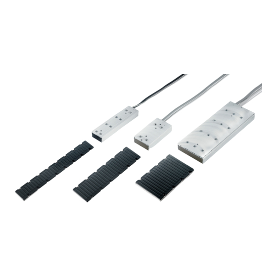
Standard features Machine concept The AL2xxx linear servomotor series from Beckhoff is not a self-contained system. It includes various components such as a coil unit and magnetic plates and must be integrated into a complete machine concept or a complete working unit. -
Page 18: Magnetic Encoder System (Mes) (Optional)
Documentation for the Magnetic Encoder System (MES)! Further information on the Magnetic Encoder System (MES) can be found on the Beckhoff home- page under: MES Feedback Documentation or in the Beckhoff Online Information System. Additional equipment You require further components for the proper installation of your linear servomotor. -
Page 19: Servo Drive And Feedback System
Servo drive and feedback system The following components are required for the construction of a complete linear axis and its operation: • Servo drive, e.g.: AX5xxx from Beckhoff Automation GmbH. • Graduated rule and linear displacement transducer or the MES feedback system without graduated rule •... -
Page 20: Mechanical Installation
Make sure that the magnetic plates are fastened in your machine before removing the protective plates. Put the protective plates back onto the magnetic plates before dismantling them. Do not bring any soft-magnetic objects (iron) closer than 10 cm to the magnetic side of the magnetic plates. Version: 6.3 AL2000... -
Page 21: Order Of Assembly Of The Work Unit
Ensure that enough clearance is maintained, or else use a spacer plate at least 1 mm thick. See also the section entitled Installation of the water cooling [} 40] (additional installation in- structions / water cooling). AL2000 Version: 6.3... -
Page 22: Assembling The Magnetic Plates
(4) in the magnetic plate (3). of the track. • Insert the locating pins (2) into the positioning holes (2) in the machine bed (1). • Manufacture the tapped holes (5) analogous to the mounting holes (6) in the magnetic plate (3). Version: 6.3 AL2000... -
Page 23: Attachment Of The Magnetic Plates
Coil unit and magnetic plate In the case of the motors from the AL2000 and AL2400 series, observe the offset of the coil unit to the magnetic plate. The AL2800-0 series lines up flush with the magnetic plate on one side. The installation position of the respective motor is to be taken from the relevant dimensional drawings. -
Page 24: Coupling Of Linear Servomotors
= phase distance “Phase L1 / Motor 1” to M1M2 M1M2 “Phase L1 / Motor 2” “Phase L1 / Motor 2” x = Housing clearance x = Housing clearance z = Distance of the locating pin holes z = Distance between the mounting holes Version: 6.3 AL2000... -
Page 25: Calculation Of The Offset
Offset = 0 L1/L1‘ L2/L2‘ L3/L3‘ L1/L1‘ L2/L3‘ L3/L2‘ L1/L1‘ L2/L3‘ L3/L2‘ Offset = 1 L1/L3‘ L2/L1‘ L3/L2‘ L1/L2‘ L2/L1‘ L3/L3‘ L1/L3‘ L2/L2‘ L3/L1‘ Offset = 2 L1/L2‘ L2/L3‘ L3/L1‘ L1/L3‘ L2/L2‘ L3/L1‘ L1/L2‘ L2/L1‘ L3/L3‘ AL2000 Version: 6.3... -
Page 26: Positions Of The Phase Lines
Mechanical installation 7.4.5 Positions of the phase lines 7.4.5.1 Phase lines AL20xx 7.4.5.2 Phase lines AL24xx Modell AL2403 AL2406 AL2412 A 2418 43.5 20.5 7.4.5.3 Phase lines AL28xx-0 air-cooled Version: 6.3 AL2000... - Page 27 Mechanical installation 7.4.5.4 Phase lines AL28xx-1 water-cooled AL2000 Version: 6.3...
-
Page 28: Minimum Distance Between The Motors
= (43 mm + 46 mm + 96 mm + 96 mm) / 16 mm = 17.56 n = 3 (rounded up) n = 18 (rounded up) = 3 * 16mm – 23mm - 22mm = 3mm = 18 * 16mm - 43mm - 46mm = 199mm Version: 6.3 AL2000... -
Page 29: Dismantling Sequence
7. Move the carriage to the other side. Secure the carriage in such a way as to prevent unwanted move- ment. 8. Cover each magnetic plate that needs to be removed with a neutralizing protective plate. 9. Remove the remaining magnetic plates. 10. Remove the coil unit from the carriage. AL2000 Version: 6.3... -
Page 30: Electrical Installation
Connection with pre-assembled cables and connector box AL225x [} 33] • Use only cables approved by Beckhoff for the operation of the AL2xxx. • Route the power and encoder cables as separately as possible from one another (separation > 20 cm). -
Page 31: Connection Of Motors
If the motors are ordered with single conductors, any connector can be assembled. The assignment of the signals to the conductors is given in the tables below. Power Line Signal Green/Yellow Weave Shield Temperature contact Line Signal White Green Brown Yellow Weave Shield AL2000 Version: 6.3... -
Page 32: M23 Connector For Power Supply And D-Sub Connector For Temperatur Contact
M23 connector for power supply and D-Sub connector for temperatur contact Motors with connection plugs Power supply Temperature contact ZS4000-2040 ZS4000-2030 Power connector Contact Signal Connector M23 (8-poles) Case Shield Temperature contact Contact Signal D-Sub Connector (9-poles) Case Shield Version: 6.3 AL2000... -
Page 33: Connection With Pre-Assembled Cables And Connector Box Al225X
Beckhoff offers preassembled motor and feedback cables for safe, faster and flawless installation of the motors. Beckhoff cables have been tested with regard to the materials, shielding and connectors used. They ensure proper functioning and compliance with statutory regulations such as EMC, UL etc. The use of other cables may lead to unexpected interference and invalidate the warranty. -
Page 34: Ax5000 Connection Diagram With Mes And Sin/Cos Encoder Without Zero Pulse
Electrical installation 8.3.1 AX5000 connection diagram with MES and Sin/Cos encoder without zero pulse * If no ConnectorBox is used, the ZK4540-0020-xxxx thermal protection contact cable is additionally required. This is to be connected to X14 / 24. Version: 6.3 AL2000... -
Page 35: Ax5000 Connection Diagram For Al2Xxx And Absolute Value Encoder
Electrical installation 8.3.2 AX5000 connection diagram for AL2xxx and absolute value encoder * If no ConnectorBox is used, the ZK4540-0020-xxxx thermal protection contact cable is additionally required. This is to be connected to X14 / 24. AL2000 Version: 6.3... -
Page 36: Ax5000 Connection Diagram For Al2Xxx And Sin/Cos Encoder With Zero Pulse
Electrical installation 8.3.3 AX5000 connection diagram for AL2xxx and Sin/Cos encoder with zero pulse * If no ConnectorBox is used, the ZK4540-0020-xxxx thermal protection contact cable is additionally required. This is to be connected to X14 / 24. Version: 6.3 AL2000... -
Page 37: Ax5000 Connection Diagram For Al2Xxx And Ttl Encoder With Zero Pulse
Electrical installation 8.3.4 AX5000 connection diagram for AL2xxx and TTL encoder with zero pulse * If no ConnectorBox is used, the ZK4540-0020-xxxx thermal protection contact cable is additionally required. This is to be connected to X14 / 24. AL2000 Version: 6.3... -
Page 38: Temperature Sensor
The basic temperature. tolerance is around ±5ºC (with shunt resistors). T (ºC) (Ω) 1010 1049 1130 1214 1301 1392 1487 1585 1687 1792 1900 2012 Version: 6.3 AL2000... -
Page 39: Polarity Test
All linear servomotors from Beckhoff are wired and connected in exactly the same way, so that a single test is sufficient in order to determine the polarity of a motor/graduated rule combination. If more than one axis is being constructed in a similar way, the polarity will be identical. -
Page 40: Installation Of The Water Cooling
In the case of the AL28xx series the water cooling represents an option that must be ordered explicitly so that it can be used. NOTE Consequential damages due to leaking water cooling Beckhoff can accept no responsibility for any damage resulting from a leaky water cooling system Requirements AL20xx AL28xx-100x... -
Page 41: Installation Of The Water Cooling Connections
Water cooling connections that can be used for hoses with an inside diameter of 4 mm are, for example, the Festo PU-4 pneumatic or the very flexible PVC hose Rauclair E 4x1. Both hoses and connections can withstand a pressure of 2 bar. AL2000 Version: 6.3... -
Page 42: Connecting The Hoses
This method of connection does reduce the pressure drop, although only when cavitation-free Y- branches with a diameter of 6-8 mm are used. The connections of the cooling water pipe can extend beyond the dimensions of the motor part. This must be observed when designing the carriage. Version: 6.3 AL2000... -
Page 43: Commissioning
• parameters for the position controller (position loop), • pole spacing: 24mm, • maximum speed (rpm), • number of increments or periods for one rotation (the pole division length divided by the number of increments per pole division). AL2000 Version: 6.3... -
Page 44: Optimising The Control Settings
In this respect, be sure to also read the instructions in the manuals for the servo drive employed. Adjustment of the controller The position controller can only be adjusted correctly if the speed controller has been adjusted cor- rectly beforehand. Version: 6.3 AL2000... -
Page 45: Troubleshooting
Connector is not properly plugged Check the plug connector Break in cable, cable crushed or Check cables similar Internal error Read out the error messages Brake does not grip Required holding force Check the design Brake faulty Replace the motor brake AL2000 Version: 6.3... -
Page 46: Technical Data
The overall mounting height over the magnetic plate and coil unit is given in the dimensional drawings. If this height is adhered to, the air gap will be correct. Version: 6.3 AL2000... -
Page 47: Al20Xx
4 x cable diameter; static Motor cable Outer diameter 9.60 mm 11.90 mm Core cross-sectional area 4 x 1.0 mm² 4 x 2.5 mm² Temperatur sensor cable Outer diameter 4.30 mm Core cross-sectional area 4 x 0.14 mm² AL2000 Version: 6.3... -
Page 48: Dimensional Drawing
Technical data 11.2.1 Dimensional drawing Version: 6.3 AL2000... -
Page 49: Al24Xx
4 x cable diameter; static Minimal bending radius 10 x cable diameter, dynamic Motor cable Outer diameter 9 mm Core cross-sectional area 4 x 0.5 mm² Temperatur sensor cable Outer diameter 4.3 mm Core cross-sectional area 4 x 0.14 mm² AL2000 Version: 6.3... -
Page 50: Dimensional Drawing
Technical data 11.3.1 Dimensional drawing Version: 6.3 AL2000... -
Page 51: Al28Xx-0 Air-Cooled
0.5 m Minimal bending radius 4 x cable diameter; static Motor cable Outer diameter 11.9 mm Core cross-sectional area 4 x 2.5 mm² Temperatur sensor cable Outer diameter 4.3 mm Core cross-sectional area 4 x 0.14 mm² AL2000 Version: 6.3... -
Page 52: Dimensional Drawing
Technical data 11.4.1 Dimensional drawing Version: 6.3 AL2000... -
Page 53: Al28Xx-1 Water-Cooled
Suitable servo drive Linear motor winding AX5112 AX5118 Linear motor winding AX5118 AX5125 AX5140 Motor data Configuration 3-phase synchronous linear motors; 400 – 480 V AC Temperature sensor PTC 1 kΩ & KTY83-122 Air gap 0.5 mm AL2000 Version: 6.3... - Page 54 11.9 mm 16.9 mm Core cross-sectional area 4 x 2.5 mm² 4 x 6 mm² 4 x 2.5 mm² 4 x 6 mm² Temperatur sensor cable Outer diameter 4.3 mm Core cross-sectional area 4 x 0.14 mm² Version: 6.3 AL2000...
-
Page 55: Dimensional Drawing
Technical data 11.5.1 Dimensional drawing AL2000 Version: 6.3... -
Page 56: Calculation Of The Brake Resistor
= maximum power of the brake resistor in Watts (W) = continuous power of the brake resistor in Watts (W) rated M = moved mass (carriage + load) in kg V = carriage velocity in m/s = braking time in s = cycle time in s Version: 6.3 AL2000... -
Page 57: Support And Service
Beckhoff's branch offices and representatives Please contact your Beckhoff branch office or representative for local support and service on Beckhoff products! The addresses of Beckhoff's branch offices and representatives round the world can be found on her internet pages: http://www.beckhoff.com You will also find further documentation for Beckhoff components there. - Page 59 More Information: Beckhoff Automation GmbH & Co. KG Hülshorstweg 20 33415 Verl Germany Phone: +49 5246 9630 info@beckhoff.com www.beckhoff.com...
Need help?
Do you have a question about the AL2000 and is the answer not in the manual?
Questions and answers