Beckhoff AM8000 Series Operation Instructions Manual
Synchronous-servomotor
Hide thumbs
Also See for AM8000 Series:
- Operating instructions manual (40 pages) ,
- Operation instructions manual (123 pages)

Related Manuals for Beckhoff AM8000 Series


Summary of Contents for Beckhoff AM8000 Series
- Page 1 AM8000 + AM8500 Synchronous-servomotor Operation instructions | EN 10/07/2019 | Version 4.1...
-
Page 2: Table Of Contents
Version numbers............................... 6 Scope of the documentation .......................... 6 Staff qualification............................... 7 Safety and instruction ............................ 8 Explanation of symbols ............................. 8 Beckhoff Services ............................. 9 For your safety.............................. 10 Safety pictograms ............................ 10 General safety instructions .......................... 11 Product overview............................... 13 Name plate.............................. - Page 3 Table of content Prerequisites during operation ........................ 70 After operation .............................. 70 Maintenance and cleaning .......................... 71 Cleaning materials ............................ 71 Intervals ................................ 72 Accessories................................ 73 Connecting cables ............................ 73 iTec extension.............................. 73 speedtec extension ............................ 73 Shaft seal ................................ 73 Gear unit .................................
-
Page 4: Documentation Notes
Documentation notes D o c u m e n t a t i o n n o t e s The documentation has been prepared with care. Beckhoff products Disclaimer are subject to continuous further development. We reserve the right to revise the documentation at any time and without notice. - Page 5 • Improper use • Use of untrained personnel • Use of unauthorized spare parts © Beckhoff Automation GmbH & Co. KG, Germany Copyright The copying, distribution and utilization of this document as well as the communication of its contents to others without express autho- rization is prohibited.
-
Page 6: Version Numbers
Product features The product features specified in the latest version of the original operating instructions are always applicable. Further information given on the product pages of the Beckhoff homepage, in emails or in other publications is not authoritative. Issue Comment... -
Page 7: Staff Qualification
The provisions of the accident prevention regulations must be complied with. Customer service Customer service is provided by technicians who have been demonstrably trained and authorized by Beckhoff or the machine manufacturer to work on the respective machine or plant. Version: 4.1 AM8000 & AM8500... -
Page 8: Safety And Instruction
Documentation notes Read the contents that refer to the activities you have to perform Safety and instruction with the product. Always read the chapter "For your safety", [Page 10] in the operating instructions. Observe the warnings in the chapters, so that you handle the product properly and safely. Various symbols are used in the interest of clarity: Explanation of symbols ►... -
Page 9: Beckhoff Services
Verl, at branch offices or, by arrangement, at the customer's premises. Hotline: +49(0)5246/963-5000 Fax: +49(0)5246/963-95000 E-mail: training@beckhoff.com Web: www.beckhoff.de/training The Beckhoff Service Centre supports you in all aspects of after- Service sales service (on-site service, repair service, spare parts service). Hotline: +49(0)5246/963-460 Fax: +49(0)5246/963-479 E-mail: service@beckhoff.com Web: www.beckhoff.de/service... -
Page 10: For Your Safety
Work particularly thor- oughly, not under time pressure and responsibly towards other peo- ple. On Beckhoff products you will find attached or lasered safety pic- Safety pictograms tograms, which vary depending on the product. They serve to pro- tect people and to prevent damage to the products. -
Page 11: General Safety Instructions
For your safety In this chapter you will find notes on safety when handling the mo- General safety instruc- tors. They cannot run independently. The motors are therefore re- tions garded as incomplete machines. They must be installed in a ma- chine / plant by the machine manufacturer. - Page 12 For your safety Avoid contact with DC link capacitors DC+ and DC- During operation Measure the voltage at the DC link capacitors! Observe the follow- ing delay times after disconnecting from the mains supply: • AX5101 to AX5125 and AX520x 5 minutes •...
-
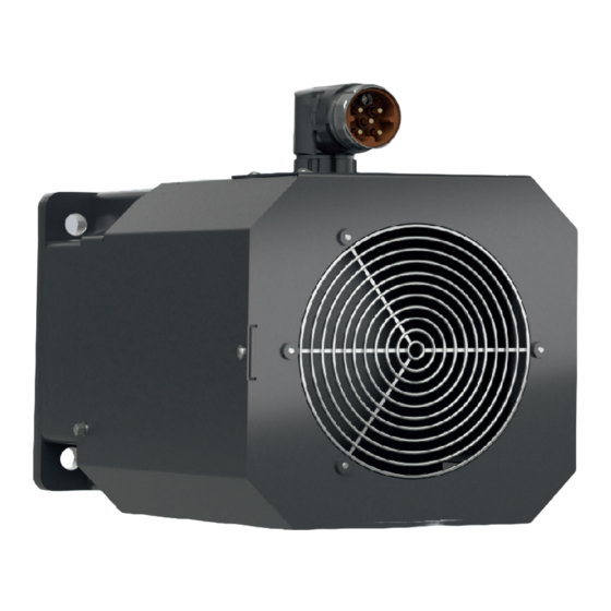
Page 13: Product Overview
Product overview P r o d u c t o v e r v i e w Number Explanation Power / feedback connection Sealing air connection [+] Eyebolt mounting lugs; only for AM807x Motor shaft Radial shaft-sealing ring [+] Name plate Motor housing Name plate Item number... -
Page 14: Type Key
9 = At AM805x, AM855x and AM802x, flange compatible with AM3x5x and AM312x Undefined Connection 0 = Rotatable angled plug or terminal box 3.2.1 Motor sizes matching the adapter for gear unit mounting Flange sizes Beckhoff flange size AM3000 AM3100 AM3500 AM8000 AM8100 AM8500... -
Page 15: Product Characteristics
Product overview Brushless three-phase synchronous motors Product characteristics Brushless three-phase synchronous motors have no electrical con- tact between rotor and stator. This means that the motor has no slip rings or commutators, which facilitates longer service life of the mo- tor. -
Page 16: Ordering Options
Product overview Order options are defined by the type key and must be ordered sep- Ordering options arately. The listed components cannot be retrofitted. 3.4.1 Feather key A feather key serves to transmit torques to an output element. The motors are available with feather key groove and fitted feather key according to DIN6885. -
Page 17: Intended Use
Improper use cal data", [Page 18] is considered improper and therefore prohib- ited. Beckhoff servomotors of the AM8000 & AM8500 series Beckhoff are not suitable for use in the following areas: • ATEX zones without suitable housing • Areas with aggressive environments, e.g. aggressive gases or... -
Page 18: Technical Data
Characteristic torque and speed curves Definitions Detailed information on characteristic curves can be found under: www.beckhoff.de -> Beckhoff motor curves External fan performance data Detailed information on the performance data of the external fan can be found in chapter: Mechanical installation: "Performance data of the external fan",... -
Page 19: Data For Operation And Environment
Technical data Beckhoff products are designed for operation under certain environ- Data for operation and mental conditions, which vary depending on the product. The follow- environment ing specifications must be observed for operation and environment in order to achieve the optimum service life of the products. -
Page 20: Am801X
Technical data AM801x Electrical data AM80xx Standstill torque* M [Nm] 0.20 0.38 0.52 Standstill current I 0.76 1.30 1.65 orms Maximum mechanical speed N [min 10,000 Maximum rated mains voltage U Peak current I 2.30 4.55 5.90 0max Peak torque M [Nm] 0.68 1.37... - Page 21 • Centring hole according to DIN 332-D Force diagram Beckhoff load / force calculator The software is used to display axial and radial forces on the mo- tor shaft. These are shown in the following example for an AM8011 without holding brake.
-
Page 22: Am802X
Technical data AM802x Electrical data AM80xx Standstill torque* M [Nm] 0.50 0.50 0.80 0.80 1.20 1.20 Standstill current I 0.85 1.60 1.50 2.44 2.20 3.40 orms Maximum mechanical speed N [min 12000 Maximum rated mains voltage U Peak current I 4.90 8.60 7.70... -
Page 23: Am802X
Technical data Optional holding brake [+] AM802x Holding torque at 120 °C M [Nm] Supply voltage U 24; +6 % to -10 % Electrical power P Current I Release delay time t [ms] Application delay time t [ms] • All figures in millimeters Dimensional drawing Motor Z - Brake... - Page 24 Technical data Beckhoff load / force calculator Force diagram The software is used to display axial and radial forces on the mo- tor shaft. These are shown in the following example for an AM8022 without holding brake. • Download load / force calculator ───...
-
Page 25: Am803X & Am853X
Technical data AM803x & AM853x Electrical data AM80xx / AM85xx Standstill torque* M [Nm] 1.37 1.38 1.40 2.38 2.37 2.37 3.20 3.22 3.22 Standstill current I 1.00 1.95 3.20 1.70 2.95 5.10 2.10 4.10 6.80 orms Maximum mechanical speed N [min 10000 Maximum rated mains voltage U... - Page 26 Technical data Optional holding brake [+] AM8031 AM8531 AM8032 AM8532 AM8033 Holding torque at 120 °C M [Nm] Supply voltage U 24; +6 % to -10 % Electrical power P Current I 0.33 0.33 0.33 0.33 0.36 Release delay time t [ms] Application delay time t [ms] •...
- Page 27 Technical data Beckhoff load / force calculator Force diagram The software is used to display axial and radial forces on the mo- tor shaft. These are shown in the following example for an AM8032 without holding brake. • Download load / force calculator Version: 4.1...
-
Page 28: Am804X & Am854X
Technical data AM804x & AM854x Electrical data AM80xx / AM85xx Standstill torque* M [Nm] 2.37 2.45 2.40 4.10 4.10 4.10 5.65 5.65 5.60 Standstill current I 1.65 3.00 5.25 2.15 4.10 6.90 2.90 5.40 9.30 orms Maximum mechanical speed N [min 9000 Maximum rated mains voltage U... - Page 29 Technical data Optional holding brake [+] AM804x AM854x Holding torque at 120 °C M [Nm] Supply voltage U 24; +6 % to -10 % Electrical power P Current I 0.54 Release delay time t [ms] Application delay time t [ms] • All figures in millimeters Dimensional drawing Motor Z - Brake...
- Page 30 Technical data Beckhoff load / force calculator Force diagram The software is used to display axial and radial forces on the mo- tor shaft. These are shown in the following example for an AM8042 without holding brake. • Download load / force calculator ───...
-
Page 31: Am805X & Am855X
Technical data AM805x & AM855x Electrical data AM80xx / AM85xx Standstill torque* M [Nm] 4.80 4.90 4.90 8.20 8.20 8.20 11.40 11.40 11.40 Standstill current I 2.70 4.75 8.50 3.30 6.30 11.30 4.70 8.80 15.60 orms Maximum mechanical speed N [min 9000 Maximum rated mains voltage U... - Page 32 Technical data Optional holding brake [+] AM8051 AM8551 AM8052 AM8552 AM8053 Holding torque at 120 °C M [Nm] Supply voltage U 24; +6 % to -10 % Electrical power P Current I 0.54 0.54 0.54 0.54 0.51 Release delay time t [ms] Application delay time t [ms] •...
- Page 33 Technical data • The flange of version AM8x5x-xxxx-9000 is compatible with Dimensional drawing AM3x5x • All figures in millimeters Motor Z – Brake AM8051-xxxx-9000 136,5 183,5 AM8052-xxxx-9000 169,5 216,5 AM8053-xxxx-9000 202,5 251,5 AM8551-xxxx-9000 183,5 216,5 AM8552-xxxx-9000 216,5 251,5 AM8553-xxxx-9000 251,5 284,5 Feather key [+] •...
- Page 34 Technical data Beckhoff load / force calculator Force diagram The software is used to display axial and radial forces on the mo- tor shaft. These are shown in the following example for an AM8052 without holding brake. • Download load / force calculator ───...
- Page 35 Technical data 4.7.4 AM805x & AM855x with fan cover [+] Electrical data AM80xx / AM85xx Standstill torque* M [Nm] 6.20 6.30 6.30 10.70 10.70 9.60 15.40 15.40 13.30 Standstill current I 3.50 5.80 11.10 4.30 8.50 13.60 6.40 11.90 18.60 orms Maximum mechanical speed N [min...
- Page 36 Technical data Optional holding brake [+] AM8051 AM8551 AM8052 AM8552 AM8053 AM8553 Holding torque at 120 °C M [Nm] Supply voltage U 24; +6 % to -10 % Electrical power P Current I 0.54 0.54 0.54 0.54 0.51 0.51 Release delay time t [ms] Application delay time t [ms]...
- Page 37 Technical data • The flange of version AM8x5x-9000 is compatible with AM3x5x Dimensional drawing • Illustration with fan cover [+] • All figures in millimeters Motor Y / Z AM8051-xxxA-9000 205,5 AM8051-xxxB-9000 252,5 AM8052-xxxA-9000 238,5 AM8052-xxxB-9000 285,5 AM8053-xxxA-9000 271,5 AM8053-xxxB-9000 320,5 AM8551-xxxA-9000 252,5...
-
Page 38: Am806X & Am856X
Technical data AM806x & AM856x Electrical data AM80xx / AM85xx Standstill torque* M [Nm] 12.80 12.80 12.80 21.10 21.10 21.10 29.00 29.00 29.00 Standstill current I 4.00 7.80 13.10 6.20 12.40 20.30 8.70 17.20 29.50 orms Maximum mechanical speed N [min 6000 Maximum rated mains voltage U... - Page 39 [ms] Servomotor AM8064 in preparation: The mechanical and electrical data of the AM8064 servomotor are updated in Version 4.1. Further information can be found under the following link: www.beckhoff.com • All figures in millimeters Dimensional drawing Motor Z – Brake...
- Page 40 Centring hole according to DIN 332-D M12 x 28 Force diagram Beckhoff load / force calculator The software is used to display axial and radial forces on the mo- tor shaft. These are shown in the following example for an AM8062 without holding brake.
- Page 41 Technical data 4.8.4 AM806x & AM856x with fan cover [+] Electrical data AM80xx / AM85xx Standstill torque* M [Nm] 17.10 17.10 15.50 29.90 29.90 28.10 41.40 41.40 40.10 Standstill current I 5.20 10.10 15.80 8.70 17.40 28.70 11.60 24.00 39.80 orms Maximum mechanical speed N [min...
- Page 42 The mechanical and electrical data, as well the dimensional draw- ings of the AM8064 servomotor with fan cover [+] are updated in Version 4.1. Further information can be found under the following link: www.beckhoff.com • Illustration with fan cover [+] Dimensional drawing •...
- Page 43 Technical data • Illustration with fan cover [+] and K-N-L winding Dimensional drawing • All figures in millimeters Motor Y / Z AM8062-xKxA-xxx0 AM8062-xKxB-xxx0 AM8062-xNxA-xxx0 AM8062-xNxB-xxx0 AM8063-xLxA-xxx0 AM8063-xLxB-xxx0 AM8562-xKxA-xxx0 AM8562-xNxA-xxx0 AM8562-xKxB-xxx0 AM8562-xNxB-xxx0 AM8563-xLxA-xxx0 Feather key [+] • Centring hole according to DIN 332-D M12 x 28 Version: 4.1 AM8000 &...
- Page 44 Technical data • Illustration with fan cover [+] and R-Q-T winding Dimensional drawing • All figures in millimeters Motor Y / Z AM8062-xRxA-xxx0 AM8062-xRxB-xxx0 AM8063-xQxA-xxx0 AM8063-xQxB-xxx0 AM8063-xTxA-xxx0 AM8063-xTxB-xxx0 AM8562-xRxA-xxx0 AM8562-xRxB-xxx0 AM8563-xQxA-xxx0 AM8563-xTxA-xxx0 Feather key [+] • Centring hole according to DIN 332-D M12 x 28 ───...
-
Page 45: Am807X
Technical data AM807x Electrical data AM80xx Standstill torque* M [Nm] 31.8 31.8 29.0 54.6 54.6 50.0 72.6 72.6 70.0 92.0 92.0 92.0 Standstill current I 17.8 28.2 11.1 20.6 39.0 14.7 27.9 45.6 17.9 34.9 49.8 orms Maximum mechanical speed N [min 5000 Maximum rated mains voltage U... - Page 46 Technical data Optional holding brake [+] AM807x Holding torque at 120 °C M [Nm] Supply voltage U 24; +6 % to -10 % Electrical power P Current I 1.21 Release delay time t [ms] Application delay time t [ms] • All figures in millimeters Dimensional drawing Motor Z - Brake...
- Page 47 Technical data • Illustration with OCT feedback Dimensional drawing • All figures in millimeters Motor Z - Brake AM8071 284,5 AM8072 341,5 AM8073 398,5 AM8074 398,5 Feather key [+] • Centring hole according to DIN 332-D M12 x 28 Version: 4.1 AM8000 &...
- Page 48 Technical data Beckhoff load / force calculator Force diagram The software is used to display axial and radial forces on the mo- tor shaft. These are shown in the following example for an AM8072 without holding brake. • Download load / force calculator ───...
- Page 49 Technical data • Illustration with terminal box and T winding Dimensional drawing • All figures in millimeters Motor Z – Brake AM8071 284,5 Feather key [+] • Centring hole according to DIN 332-D M12 x 28 Version: 4.1 AM8000 & AM8500 ───...
- Page 50 Technical data 4.9.5 Terminal box assignment Power and feedback Temperature and brake Wire Slot Wire Slot ─── AM8000 & AM8500 Version: 4.1...
- Page 51 Technical data 4.9.6 AM807x with fan cover [+] Electrical data AM80xx Standstill torque* M [Nm] 42.8 42.8 41.2 80.7 80.7 74.0 95.0 Standstill current I 12.6 23.8 41.1 16.1 29.2 53.0 19.8 37.4 66.5 25.8 49.4 69.2 orms Maximum mechanical speed N [min 5000 Maximum rated mains voltage U...
- Page 52 Technical data Optional holding brake [+] AM807x Holding torque at 120 °C M [Nm] Supply voltage U 24; +6 % to -10 % Electrical power P Current I 1.21 Release delay time t [ms] Application delay time t [ms] • Illustration with fan cover [+] Dimensional drawing •...
- Page 53 Technical data • Illustration with fan cover [+], terminal box and T-U winding Dimensional drawing • All figures in millimeters Motor Y / Z AM8074-xT0A-xxxx 507,5 AM8074-xU0A-xxxx 507,5 Feather key [+] • Centring hole according to DIN 332-D M12 x 28 Version: 4.1 AM8000 &...
-
Page 54: Scope Of Supply
Scope of supply S c o p e o f s u p p l y Check missing or damaged parts Check your delivery for completeness. If any parts are missing or became damaged during transport, contact the carrier, manufac- turer or our service department immediately. -
Page 55: Transport And Storage
Transport and storage T r a n s p o r t a n d s t o r a g e Avoid damage to the motors and resulting loss of warranty Observe the conditions specified in the following chapters for Transport and Storage. -
Page 56: Transport
Transport and storage Transport Do not enter the area below suspended motors Use suitable means of transport and secure the motor against fall- ing. Dropping the motor could lead to fatal accidents. Avoid hard impacts on the motor Use suitable means of transport and secure the motor against fall- ing. -
Page 57: Long-Term Storage
Transport and storage Long-term storage Observe the maximum storage time Do not exceed the maximum storage time of two years. Exceeding the specified maximum storage time can lead to changes in the properties of the lubricant used and damage the motor during subsequent operation. -
Page 58: Technical Description
Technical description T e c h n i c a l d e s c r i p t i o n Mounting position Observe the maintenance intervals and mounting positions Carry out maintenance at regular intervals. In the horizontal IM V3 mounting position, liquid which has been left on the flange for a longer period can penetrate the motor through capillary action. -
Page 59: Protection Equipment
Calculation of the exact radial and axial forces The calculation tool Beckhoff AM8000 motors radial forces / axial forces, service life is available via www.beckhoff.de. Preferred backlash-fress coupling elements: • Double-coned collets and metal bellows couplings Version: 4.1 AM8000 &... -
Page 60: Power Derating
Technical description Power reduction may be required at high ambient temperatures or Power derating for operation at high altitudes. In addition, some motors may experi- ence power reductions depending on the feedback system installed or the holding brake [+]. The reduction affects the standstill current and the standstill torque. -
Page 61: Mechanical Installation
Mechanical installation M e c h a n i c a l i n s t a l l a t i o n Carry out all work with great care and without time pressure. The following table provides information on components for mount- Flange mounting ing the motor on the machine / system: Motor... - Page 62 Mechanical installation Mounting Do not touch hot output elements without personal protective equipment Only handle hot output elements, such as couplings or pulleys, with special thermal gloves. Avoid prolonged contact with hot com- ponents. Hot components can cause severe burns to body parts and limbs. Do not mount the drive element offset Place the drive element centered and straight on the motor shaft.
-
Page 63: Fan Cover [+]
► Fit nuts 8 and 11 with washers 9 and 10 ► Observe the tightening torques: Screws Nuts 3 Nm; size 2.5 2.5 Nm; size 7 Use Beckhoff control cable! Use the pre-assembled control cable ZK4054-6400-0xxx to connect the fan cover [+] Version: 4.1 AM8000 & AM8500 ───... - Page 64 : brown not used GND: blue not used Additional documentation for control cable ZK4054-6400-0xxx The data sheet of the control cable can be found under: www.beckhoff.com → Download → Data sheets → Cables and wires ─── AM8000 & AM8500 Version: 4.1...
-
Page 65: Electrical Installation
Connection technology bles. Mating connectors are not included in the scope of supply. To select the necessary cables, refer to the Beckhoff documentation for connecting cables [+]. In the documentation you will find a complete overview of the available cables and information on the technical data. - Page 66 Electrical installation 9.1.3 Connectors ► Push iTec connector 2 straight onto power box 1 of the motor ► Make sure that the marking points face each other ► Pay attention to the "click" sound ► Make sure that all marking points 3 are in alignment The iTec connector is then fully engaged.
- Page 67 Electrical installation ► Make sure that all markings and the lettering "open" 4 are aligned The speedtec connector is then fixed properly. Terminal box Avoid soiling and damage When dismantling the cover and connecting the terminal box and cables, make sure that no foreign objects or dirt particles enter the terminal box, the clamping ring or the M40 thread on the terminal box.
-
Page 68: Connector Assignment
"Technical data AM807x", [Page 50]. ► Make sure that the seal is correctly placed on the terminal box ► Re-install the cover 5 Beckhoff offers various power connectors and feedback connectors. Connector assignment All connectors are IP65 rated. A protective conductor connection ac- cording to VDE 0627 is provided on the housing. -
Page 69: Commissioning
• Check protective measures against moving and live parts Configuration Beckhoff recommends the use of servo drives and motors from Beckhoff in combinations, and configuration in the Beckhoff TwinCAT DriveManager. Carry out the instructions in the operating manual for servo drives: •... -
Page 70: Prerequisites During Operation
Commissioning • Pay attention to atypical noise development Prerequisites during op- • Pay attention to smoke development eration • Always check drive surfaces and cables for dirt, leaks, moisture or dust • Check temperature development • Check for lubricant leakage •... -
Page 71: Maintenance And Cleaning
Maintenance and cleaning M a i n t e n a n c e a n d c l e a n i n g Ensure safe condition for cleaning work Basically, electronic devices are not fail-safe. The condition is al- ways safe when the unit is switched off and not energized. -
Page 72: Intervals
Replace cables Fan cover [+] half-yearly Perform visual inspection and check for damage In the event of unbalance: Clean fan Contact Beckhoff Service In case of damage: Contact Beckhoff Service Power box 500 mating cycles In case of damage: Contact Beckhoff Service... -
Page 73: Accessories
Accessories A c c e s s o r i e s 12.1 Connecting cables Orange power cables and green feedback cables are used for the connection between motor and servo drive. Information on connecting a motor with a servo drive or the multi- axis servo system can be found in chapter: "Electrical installation", [Page 65]. -
Page 74: Gear Unit
Accessories Gear unit Axial load due to thermal expansion of the motor shaft To avoid displacement of the motor shaft at high temperatures, use couplings as length compensation. Directly mounted bevel gears or helical gear wheels can exceed the axial load of the floating bearing on the shaft end A. A gear unit serves to transmit a force moment or torque and is used on the motor as an output element. -
Page 75: Fault Correction
Fault correction F a u l t c o r r e c t i o n The following table describes selected malfunctions. Depending on the application, other causes may be responsible for the malfunc- tion. Conspicuous control behavior is the result of incorrect parameteriza- tion of the servo drive. - Page 76 Feedback connector not fitted correctly Check the position of the feedback connector Loose fit of the feedback connector or no contact of the plug Check the connector assembly. Contact Beckhoff Service contacts with the power socket of the motor. if necessary.
-
Page 77: Decommissioning
Hot oil can cause severe burns. Unauthorized removal of servomotor components The motors have permanent magnets in the rotor. These motors may only be dismantled by Beckhoff Automation GmbH & Co. KG. Contact Beckhoff Service for further information. Removing the motor from the machine •... -
Page 78: Guidelines And Standards
The cURus logo can be found on the "name plate", [Page 13]. Placing at disposal EU conformity Beckhoff Automation GmbH & Co KG will be pleased to provide you with EU declarations of conformity and manufacturer's decla- rations for all products on request. -
Page 79: Index
Index I n d e x Accessories Operating conditions 19 Connecting cables 73 Ordering options 16 Gear unit 74 Fan cover 17 iTec extension 73 Feather key 16 Shaft seal 73 Holding brake 16 speedtec extension 73 Sealing air connection 16 Output elements Dismantling... - Page 80 Beckhoff Automation GmbH & Co. KG Hülshorstweg 20 D-33415 Verl www.beckhoff.com info@beckhoff.com More Information: www.beckhoff.com/am8000...
Need help?
Do you have a question about the AM8000 Series and is the answer not in the manual?
Questions and answers