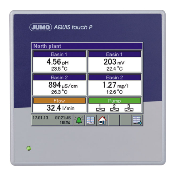
JUMO AQUIS touch P Installation Instructions Manual
Modular multichannel measuring device for liquid analysis with integrated controller and paperless recorder
Hide thumbs
Also See for AQUIS touch P:
- Operating manual (404 pages) ,
- Operating manual (370 pages) ,
- Interface description (52 pages)

Related Manuals for JUMO AQUIS touch P


Summary of Contents for JUMO AQUIS touch P
- Page 1 JUMO AQUIS touch P Modular Multichannel Measuring Device for Liquid Analysis with Integrated Controller and Paperless Recorder Type 202580 Installations Instructions Volume 2(2) b20.2581.4en_b2 V2.00/EN/00614180...
- Page 2 Caution! If the device or a sensor connected to it fails abruptly, it is likely that a dangerous overdosage has occurred! For this case, appropriate precautionary measures must be taken. NOTE! Read this operating manual before putting the device into service. Keep the operating manual at a location that is readily accessible to all users.
-
Page 3: Table Of Contents
Content Retrofitting optional boards ..........7 10.1 Inserting optional boards ..............7 10.2 Ci base calibration ................10 Calibration in general .............15 11.1 Notes ....................15 11.2 General information ................. 15 11.2.1 General procedure for calibration ............ 15 11.3 Calibration logbook ................17 Calibrating a pH measuring chain .........21 12.1 Notes .................... - Page 4 Content 14.3.1 Zero-point calibration ............... 34 Calibrating CR conductivity sensors ......35 15.1 Notes ....................35 15.2 General information ................. 35 15.2.1 Calibration methods for CR conductivity sensors (conductive) ..35 15.2.2 Calibration default settings for CR conductivity sensors ....36 15.3 CR calibration routines ..............
- Page 5 Content 18.1.2 Temperature measuring input (IN 5) ..........64 18.1.3 Universal input (IN 6) ............... 64 18.1.4 Measuring circuit monitoring base unit ..........64 18.2 Analog inputs optional boards ............65 18.2.1 Universal input (IN 11, IN 12) ............65 18.2.2 Analysis input: pH/Redox/NH ............
- Page 6 Content...
-
Page 7: Retrofitting Optional Boards
10 Retrofitting optional boards 10.1 Inserting optional boards DANGER! Insertion and removal of optional boards must be performed only by qualified personnel. To ensure electrical safety, country-specific regulations must be ob- served. The following step-by-step table explains in detail the procedure for retrofitting optional boards: Step Action... - Page 8 10 Retrofitting optional boards Step Action Disconnect all screw terminals and interface cables connected at the rear of the device. To prevent connections being interchanged, note down the assignment of the connectors to the sockets. Undo (do not remove) the two countersunk screws on the bottom of the case and remove the pan head screw on the side of the case.
- Page 9 10 Retrofitting optional boards Step Action Insert the optional board in the selected slot. Ensure that the board is seated correctly. Fill all empty slots with plastic board frames. Re-insert the rear panel of the case and fasten with 3 screws. Make sure that all the toothed lock washers for securing the screws are re-inserted (see Step 7).
-
Page 10: Ci Base Calibration
When the battery is empty a battery alarm will indicate that status. The battery must be exchanged before it is empty. The bat- tery must be exchanged by the JUMO Service department! In this case, send in the device! - Page 11 The factory settings authorize the "Master" and "Service" users for this. v Chapter 8.1.1 "Passwords and user rights", Page 61 Ensure that the electronics of the JUMO AQUIS touch P have reached operating temperature. You can view the board tempera- ture at: Device Menu r Service r Service Data r "Internal Data"...
- Page 12 10 Retrofitting optional boards Step Action Place the wire of the calibration sensor with 2 windings through the opening in the Ci sensor without connecting the ends of the wires. Start the Ci base calibration Device Menu r Service r Ci Base Calibration IN 7 to 8 Enter the cell constant for the sensor and confirm by pressing "OK".
- Page 13 10 Retrofitting optional boards Step Action Connect the ends of the wires forming the conductor loop of the calibration adapter. Set the calibration adapter to the resistance value shown in the in- struction text in the display (in the example: 20kΩ). Once the mea- surement displayed has stabilized, confirm by pressing "OK".
- Page 14 10 Retrofitting optional boards Step Action Once all measurings have been confirmed, a summary of the cali- bration data acquired appears. Confirm by pressing "OK". If the Ci base calibration fails, the procedure is canceled without acceptance of the calibration data. Protocol after successful Ci base calibration...
-
Page 15: Calibration In General
11 Calibration in general 11.1 Notes WARNING! During the calibration, the relays and analog output signals assume the config- ured states! 11.2 General information The actual electrical characteristics of analysis sensors always deviate some- what from the nominal specifications. The reasons for this include: •... - Page 16 11 Calibration in general • You must be logged in as a user with the right to perform calibrations. Fac- tory-preset users have all of these rights. v „Passwords and user rights“, Page 61 • You must ensure that the calibration default settings for the individual analy- sis inputs and, possibly, the universal inputs are set correctly.
-
Page 17: Calibration Logbook
11 Calibration in general 11.3 Calibration logbook A separate logbook is maintained for each analysis and universal input. The last 10 successful calibrations of the input concerned are saved in the cal- ibration logbook. Canceled or failed calibrations (calibrations outside the per- missible limits) are not saved in the logbook, but rather noted in the event list. - Page 18 Tapping the "Details" button opens the selected logbook entry in the detail view. The detail view displays a table with all calibration values from a calibration pro- cedure. The "Service" button is used for diagnostic purposes by trained person- nel or JUMO Service.
- Page 19 11 Calibration in general Assessment criteria pH calibrations (glass electrodes and ISFET connected to analysis measuring inputs as well as standard sig- nals connected to universal inputs) Calibration value [unit] — — < ≤ < < ≤ < Zero point [pH] 6 to 8 <...
- Page 20 11 Calibration in general Calibration of conductivity sensors (analysis measuring inputs and standard signals connected to universal inputs) Calibration value [unit] — — < ≤ < < ≤ 150 < Rel. cell constant (CR) [%] 75 to 125 < ≤ <...
-
Page 21: Calibrating A Ph Measuring Chain
12 Calibrating a pH measuring chain 12.1 Notes WARNING! During the calibration, the relays and analog output signals assume the config- ured states! 12.2 General information The calibration of pH electrodes is based on measurements in Buffer solutions with a defined pH-value. The pH values of the Buffer solutions used are speci- fied either via entry of fixed values into the calibration default settings, entered during the calibration or recognized automatically by "automatic buffer recogni- tion"... -
Page 22: Calibration Default Settings For Ph Sensors
12 Calibrating a pH measuring chain 12.2.2 Calibration default settings for pH sensors Before you can perform a calibration, you must first enter the necessary calibra- tion default settings. The possible settings for the pH Calibration are described in the following. Open the calibration default settings: Device Menu r Calibration r Select Analysis Input for pH/Redox/NH r Cali-... - Page 23 "pH buf- preferably for calibrating and fer 1 to 3" are hidden. adjusting technical pH mea- You need the JUMO PC setup program suring instruments acc. to DIN to edit Buffer set tables. 19267...
-
Page 24: Ph Calibration Routines
12 Calibrating a pH measuring chain 12.3 pH Calibration routines NOTE! You must be logged in with corresponding user rights to perform calibrations. v Chapter 8.2.1 "Log-on/Log-out", Page 74 12.3.1 Zero-point calibration Step Action Start the Zero-point calibration. Device Menu r Calibration r Select analysis input for pH/Redox/ r Open Zero-point calibration If temperature compensation was not specified in the calibration default settings, enter the temperature of the Buffer solution here... - Page 25 12 Calibrating a pH measuring chain Step Action Entry of the pH-value of the Buffer solution • without buffer recognition: Check whether the "pH buffer 1" matches the pH-value of the Buffer solution used. If a Buffer set table was not specified, the "Buffer 1 pH"...
-
Page 26: Two-Point And Three-Point Calibration
12 Calibrating a pH measuring chain 12.3.2 Two-point and Three-point calibration Step Action Start the desired Calibration routine. Device Menu r Calibration r analysis input Select analysis input for pH/Redox/NH3 r Open Two-point or Three-point calibration If temperature compensation was not specified in the calibration default settings, enter the temperatures of the Buffer solution here manually. - Page 27 12 Calibrating a pH measuring chain Step Action Entry of the pH-value of the Buffer solution • without buffer recognition: Check whether the "pH buffer 1" matches the pH-value of the Buffer solution used. If a Buffer set table was not specified, the "Buffer 1 pH"...
- Page 28 12 Calibrating a pH measuring chain...
-
Page 29: Calibrating Redox Sensors
13 Calibrating Redox sensors 13.1 Notes WARNING! During the calibration, the relays and analog output signals assume the config- ured states! 13.2 General information The calibration of Redox sensors is based on measurements in test solutions with a defined Redox potential. 13.2.1 Calibration methods for Redox sensors Zero-point calibration... -
Page 30: Calibration Default Settings For Redox Sensors
13 Calibrating Redox sensors 13.2.2 Calibration default settings for Redox sensors Before you can perform a calibration, you must first enter the necessary calibra- tion default settings. The possible settings for the Redox calibration are de- scribed in the following. Open the calibration default settings: Device Menu r Calibration r Select Analysis Input for pH/Redox/ r Calibration Default Settings... -
Page 31: Redox Calibration Routines
13 Calibrating Redox sensors 13.3 Redox calibration routines NOTE! You must be logged in with corresponding user rights to perform calibrations. v Chapter 8.2.1 "Log-on/Log-out", Page 74 13.3.1 Zero-point calibration Step Action Ensure that • the calibration default settings are correct, •... -
Page 32: Two-Point Calibration
13 Calibrating Redox sensors 13.3.2 Two-point Calibration Step Action Ensure that • the calibration default settings are correct • "Percent" is set as the Redox unit in the configuration of the Re- dox measuring input. v Chapter 13.2.2 "Calibration default settings for Redox sensors", Page 30. -
Page 33: Calibrating Ammonia Sensors
14 Calibrating ammonia sensors 14.1 Notes WARNING! During the calibration, the relays and analog output signals assume the config- ured states! 14.2 General information The calibration of ammonia sensors is based on measurements in ammonia- free test solutions. 14.2.1 Calibration methods for ammonia sensors Zero-point calibration This calibration method is used to determine the ammonia zero point. -
Page 34: Ammonia Calibration Routines
14 Calibrating ammonia sensors 14.3 Ammonia calibration routines NOTE! You must be logged in with corresponding user rights to perform calibrations. v Chapter 8.2.1 "Log-on/Log-out", Page 74 14.3.1 Zero-point calibration Step Action Start the Zero-point calibration. Device menu r Calibration r Select Analysis Input for pH/Redox/ r Zero-Point Calibration Clean the ammonia electrode and immerse it in the ammonia-free test solution. -
Page 35: Calibrating Cr Conductivity Sensors
15 Calibrating CR conductivity sensors 15.1 Notes WARNING! During the calibration, the relays and analog output signals assume the config- ured states! 15.2 General information The calibration of CR sensors is based on measurements in test solutions with a defined electrolytic conductivity. Since the electrolytic conductivity of liquids is temperature dependent, the temperature of the test solution must be sensed. -
Page 36: Calibration Default Settings For Cr Conductivity Sensors
15 Calibrating CR conductivity sensors 15.2.2 Calibration default settings for CR conductivity sensors Before you can perform a calibration, you must first enter the necessary calibra- tion default settings. The possible settings for the CR calibration are described in the following. Open the calibration default settings: Device menu r Calibration r Select CR Analysis Input r Calibration Default Settings... - Page 37 15 Calibrating CR conductivity sensors Calibration default settings for calibrating the relative cell constant Parameter Setting options Explanation Reference conductivi- 0 to 9999 mS/cm Conductivity of the reference solution Calibration default settings for calibrating the temperature coefficient Parameter Setting options Explanation Temperature com- Selection from...
-
Page 38: Cr Calibration Routines
15 Calibrating CR conductivity sensors 15.3 CR calibration routines NOTE! Conductivity measuring inputs can be configured with measuring range change- over. Accordingly, calibrations must be performed for all "accessible measuring ranges". NOTE! You must be logged in with corresponding user rights to perform calibrations. v Chapter 8.2.1 "Log-on/Log-out", Page 74 15.3.1 Calibrating the relative cell constant... - Page 39 15 Calibrating CR conductivity sensors Step Action Ensure that • the sensor has been cleaned and is immersed in the test solu- tion, • the set reference conductivity matches the conductivity value of the test solution. Wait until the measuring value displayed stabilizes and then con- firm the result of the measurement by pressing "OK".
-
Page 40: Calibrating The Temperature Coefficient
15 Calibrating CR conductivity sensors 15.3.2 Calibrating the temperature coefficient Step Action Start calibration of the temperature coefficient. Device menu r Calibration r Select CR Analysis Input r TC Cal- ibration Clean the sensor and immerse it in the sample solution. Ensure that the rel. - Page 41 15 Calibrating CR conductivity sensors Step Action • with temperature sensing A prerequisite is that temperature compensation was specified in the calibration default settings. Bring the temperature of the sample solution to the requested val- ues of the reference and operation temperatures in succession. The order does not matter.
- Page 42 15 Calibrating CR conductivity sensors...
-
Page 43: Calibrating Ci Conductivity Sensors
16 Calibrating Ci conductivity sensors 16.1 Important information WARNING! During the calibration, the relays and analog output signals assume the config- ured states! 16.2 General information The calibration of Ci sensors is based on measurements in test solutions with a defined electrolytic conductivity. -
Page 44: Calibration Default Settings For Ci Conductivity Sensors
16 Calibrating Ci conductivity sensors TC curve (for nonlinear temperature coefficients) If the conductivity of a liquid whose temperature coefficient changes with tem- perature has to be measured, this method can determine 5 temperature coeffi- cients for 5 temperature intervals. In this way, it is possible to determine a good approximation of the temperature coefficient curve. - Page 45 16 Calibrating Ci conductivity sensors Sample screen: Ci calibration default settings The calibration default settings enable the calibration routines to be accessed in the particular calibration menu. Calibration routines that are not enabled are not visible in the calibration menu. Additional calibration default settings are explained in the following table.
- Page 46 16 Calibrating Ci conductivity sensors Calibration default settings for calibrating the TC curve Parameter Setting options Explanation Temperature com- Selection from Temperature input for automatic sensing of the test/ pensation analog selection sample solution temperature during the calibration Starting temperature -50 to 250 °C The starting and final temperatures of the range for which a temperature coefficient curve is to be deter-...
-
Page 47: Ci Calibration Routines
16 Calibrating Ci conductivity sensors 16.3 Ci calibration routines NOTE! Conductivity measuring inputs can be configured with measuring range change- over. Accordingly, calibrations must be performed for all "accessible measuring ranges". NOTE! You must be logged in with corresponding user rights to perform calibrations. v Chapter 8.2.1 "Log-on/Log-out", Page 74 NOTE! Analysis inputs for inductive conductivity measurements (Ci) must undergo a... - Page 48 16 Calibrating Ci conductivity sensors Step Action Ensure that • the sensor has been cleaned and is immersed in the test solu- tion, • the set reference conductivity matches the conductivity value of the test solution. Wait until the measuring value displayed stabilizes and then con- firm the result of the measurement by pressing "OK".
-
Page 49: Calibrating The Temperature Coefficient
16 Calibrating Ci conductivity sensors 16.3.2 Calibrating the temperature coefficient Step Action Start calibration of the temperature coefficient. Device Settings Menu r Calibration r Select Ci Analysis Input or Universal Input r TC Calibration Clean the sensor and immerse it in the sample solution. Ensure that the rel. - Page 50 16 Calibrating Ci conductivity sensors Step Action • with temperature sensing A prerequisite is that temperature compensation was specified in the calibration the default settings. Bring the temperature of the sample solution to the requested val- ues of the reference and operation temperatures in succession. The order does not matter.
-
Page 51: Calibrating The Tc-Curve
16 Calibrating Ci conductivity sensors 16.3.3 Calibrating the TC-Curve Step Action Start the desired calibration of the TC-Curve. Device Menu r Calibration r Analysis Input 1 to 4 (Ci) and/or Universal Input 1 to 3 r TC-Curve Clean the sensor and immerse it in the sample solution. Ensure that the rel. - Page 52 16 Calibrating Ci conductivity sensors...
-
Page 53: Calibrating Universal Inputs
17 Calibrating universal inputs 17.1 Important information WARNING! During the calibration, the relays and analog output signals assume the config- ured states! 17.2 General information 17.2.1 Calibration methods for universal inputs Universal inputs can be configured with various operation modes for a number of different process variables (see table below). - Page 54 17 Calibrating universal inputs Two-point calibration The zero point and slope of the measuring characteristic curve are determined with the aid of 2 measurings of 2 different reference solutions. Two test solutions with defined values of the respective process variable are needed as a references.
-
Page 55: Universal Inputs Calibration Default Settings
17 Calibrating universal inputs 17.2.2 Universal inputs calibration default settings The calibration default setting available for selection depends on the configura- tion settings of the universal input. Open the calibration default settings: Device Menu r Calibration r Select Universal Input r Calibration Default Settings Calibration default settings for the individual operation modes •... - Page 56 17 Calibrating universal inputs • free chlorine, ph/Temp.-compensated In the universal inputs calibration default settings for the "free chlorine, ph/T- compensated" operation mode, the slope calibration is enabled and pre-config- ured as the only available calibration routine. Sample screen: Universal input calibration default settings in the "free chlorine, pH/T-com- pensated"...
-
Page 57: Universal Input Calibration Routines
17 Calibrating universal inputs 17.3 Universal input calibration routines This chapter explains the universal inputs calibration routines for the "linear scal- ing" and "free chlorine, ph/T-compensated" operation modes. The explanations in the corresponding calibration chapters for the "pH value measurement" and "Conductivity measurement" operation modes apply, except that three-point calibration for pH sensors is not available for universal inputs (see Chapter 17.2.1 "Calibration methods for universal inputs", Page 53). -
Page 58: Zero Point/Slope Calibration (Linear Scaling)
17 Calibrating universal inputs 17.3.1 Zero point/slope calibration (linear scaling) Step Action Start the desired Calibration routine. Device Menu r Calibration r Select Universal Input r Zero-point calibration Clean the sensor and immerse it in the test solution. Wait until the measured value displayed stabilizes and then confirm the result of the measurement by pressing "OK". -
Page 59: Two-Point Calibration (Linear Scaling)
17 Calibrating universal inputs 17.3.2 Two-point calibration (linear scaling) Step Action Start the desired Calibration routine. Device Menu r Calibration r Select Universal Input r Two-point calibration Clean the sensor and immerse it in the first test solution. Wait until the measuring value displayed stabiliz- es and then confirm the result of the measurement by pressing "OK". - Page 60 17 Calibrating universal inputs...
-
Page 61: Slope Calibration (Free Chlorine, Ph/Temp.-Compensated)
17 Calibrating universal inputs 17.3.3 Slope calibration (free chlorine, ph/Temp.-compensated) Step Action Start the slope calibration. Device Menu r Calibration r Select Universal Input r Slope Cal- ibration Clean the sensor and immerse it in the test solution. Check the displayed values for the pH value and temperature. - Page 62 17 Calibrating universal inputs Step Action Press "Yes" to accept the Calibration values determined and enter the Calibration in the Calibration logbook. Press "No" to discard the results.
-
Page 63: Technical Data
18 Technical data 18.1 Analog inputs base unit 18.1.1 Temperature measuring input (IN 4) Probe-/Signal type Connection type Measuring Measuring accu- Ambient range racy temperature influence -200 to +850 °C ≤ 0.05% of MR ≤ 50 ppm/K Pt100 DIN EN 60751 2-wire/3-wire -200 to +850 °C ≤... -
Page 64: Temperature Measuring Input (In 5)
18 Technical data 18.1.2 Temperature measuring input (IN 5) Probe-/Signal type Connection type Measuring Measuring accu- Ambient range racy temperature influence -200 to +850 °C ≤ 0.05% of MR ≤ 50 ppm/K Pt100 DIN EN 60751 2-wire/3-wire -200 to +850 °C ≤ 0.1% of MR ≤... -
Page 65: Analog Inputs Optional Boards
18 Technical data 18.2 Analog inputs optional boards 18.2.1 Universal input (IN 11, IN 12) Probe-/Signal type Connection type Measuring Measuring accu- Ambient range racy temperature influence -200 to +850 °C ≤ 0.05% of MR ≤ 50 ppm/K Pt100 DIN EN 60751 2-wire/3-wire -200 to +850 °C ≤... -
Page 66: Analysis Input: Cr (Resistive Conductivity)
18 Technical data 18.2.3 Analysis input: CR (resistive conductivity) Units µs/cm ms/cm kΩ × cm MΩ × cm Display ranges 0.0000 to 9.9999 00.000 to 99.999 000.00 to 999.99 0000.0 to 9999.9 00000 to 99999 Temperature compensation TC-linear, natural water DIN EN 27888, natural water with expanded range, ASTM D-1125-95 for neutral (NaCl), acidic (HCl) and alkaline (NaOH) impurities... -
Page 67: Analysis Input: Ci (Conductivity, Inductive)
18 Technical data 18.2.4 Analysis input: Ci (conductivity, inductive) Units µs/cm ms/cm Measuring/display ranges 0.0000 to 9.9999 00.000 to 99.999 000.00 to 999.99 0000.0 to 9999.9 00000 to 99999 Temperature compensation TC linear TC curve natural water natural water with expanded temperature range NaOH 0 to 12% NaOH 25 to 50% 0 to 25%... -
Page 68: Temperature Compensations
18 Technical data 18.2.5 Temperature compensations Compensation type Compensation range TC linear -50 to +250 °C TC curve -50 to +250 °C -50 to +250 °C natural water according to DIN EN 27888 0 to 36 °C natural water with 0 to 100 °C expanded temperature range ASTM D-1125-95 (neutral, alkaline, and... -
Page 69: Measuring Circuit Monitoring, Optional Boards
18 Technical data 18.2.6 Measuring circuit monitoring, optional boards Input/Sensor Underrange/ Short circuit/ Open circuit Special fea- overrange sensor break tures pH-value (glass elec- Configurable Configurable trode) Impedance mea- Impedance mea- surement surement pH-value (ISFET) Resistive conductivity Configurable Only with 4-wire circuit Inductive conductivity Universal input for con-... -
Page 70: Analog Outputs Of Base Unit And Optional Boards
Configuration. Sensors and transmitters should be supplied from voltage supply outputs on the JUMO AQUIS touch P. An externally supplied voltage signal must not have a voltage over 28 V. All digital inputs IN 1 to 3 are suitable for connecting proximity switches. Recommended types are: Wachendorff P2C2B1208NO3A2 and Balluff BES M12EG-PSC80F-BP03. -
Page 71: Binary Outputs, Optional Boards
18 Technical data 18.7 Binary outputs, optional boards Optional card Switching out- Ampacity at re- Contact life Special features sistive load Relay output, dual nor- 2 normally open 3 A at AC 250 V 150,000 mally open contacts contacts switching cycles Relay output, single 1 changeover changeover contact... -
Page 72: Interfaces
18 Technical data 18.9 Interfaces 18.9.1 Serial interface RS485 (base unit ) Protocol Data formats Device address- Baud rates in Connection baud Modbus (slave) 8 - 1 - no parity 1 to 254 9600 Spring-cage 8 - 1 - odd parity 19200 terminals 8 - 1 - even parity... -
Page 73: Ethernet Optional Board (10/100Base-T)
Modbus TCP/IP enables Modbus users to communicate via a LAN, provided this is connected to the LAN (e.g. via gateways). To configure Modbus communication you will require the interface description for the JUMO AQUIS touch P. Enlist the help of your network administrator or an IT specialist for the IP-configuration. -
Page 74: Usb Interfaces
USB 2.0 data memory Type A Read/write device settings, Save Service data Update the firmware USB device interface Device setting via PC JUMO PC setup USB port setup program, program, Type Mini-B Extract, archive, evalu- JUMO PCC/PCA 3000 measurement data software The recording function stores measurement data in a ring buffer inside the device. -
Page 75: Electrical Data
18 Technical data 18.10 Electrical data Voltage supply (switch-mode) AC 110 to 240 V +10/-15%; 48 to 63 Hz or AC/DC 24 V +30/-25 %; 48 to 63 Hz electrical safety According to EN 61010, part 1 overvoltage category III, pollution degree 2 Max. -
Page 76: Case
18 Technical data 18.12 Case Site altitude maximum 2000 m above sea level Case type Plastic front frame with metal case barrel (for indoor use only) Materials Plastic front panel UL 94 V0 Case barrel from zinc-plated steel sheet Dimensions of the front 96 mm ×... -
Page 77: Functions
18 Technical data 18.13 Functions 18.13.1 Controller channels Number Controller type Two-state controllers Three-state controllers Continuous controller Coarse/fine controller Modulating controllers Continuous controller with position controller Controller structure P, PI, PD, PID Controller outputs For each controller channel, 2 outputs configurable as: pulse length output, pulse frequency output, (maximal 240 pulses per minute), continuous output Disturbance feedforward con-... -
Page 78: Recording Function
History function Archiving/evaluation Yes, (with JUMO PCA 3000 evalu- ation software ) A freely configurable set of input variables can be pooled in one group. Each group has its own display screen. The group affiliation is considered for data storage to enable eval- uation via PC. - Page 79 18 Technical data...
- Page 80 18 Technical data...
- Page 82 JUMO GmbH & Co. KG JUMO Instrument Co. Ltd. JUMO Process Control, Inc. Street address: JUMO House 6733 Myers Road Moritz-Juchheim-Straße 1 Temple Bank, Riverway East Syracuse, NY 13057, USA 36039 Fulda, Germany Harlow - Essex CM20 2DY, UK Phone:...
Need help?
Do you have a question about the AQUIS touch P and is the answer not in the manual?
Questions and answers