JUMO AQUIS touch P Operating Manual
Modular multichannel measuring device for
liquid analysis with integrated controller and
paperless recorder
Hide thumbs
Also See for AQUIS touch P:
- Operating manual (404 pages) ,
- Interface description (52 pages) ,
- Installation instructions manual (82 pages)

Related Manuals for JUMO AQUIS touch P


Summary of Contents for JUMO AQUIS touch P
- Page 1 JUMO AQUIS touch P Modular Multichannel Measuring Device for Liquid Analysis with Integrated Controller and Paperless Recorder Type 202580 Operating Manual 20258000T90Z001K000 V3.00/EN/00607974...
- Page 2 Caution! If the device or a sensor connected to it fails abruptly, it is likely that a dangerous overdosage has occurred! For this case, appropriate precautionary measures must be taken. NOTE! Read this operating manual before putting the device into service. Keep the operating manual at a location that is readily accessible to all users.
-
Page 3: Table Of Contents
Content Safety information ............13 Warning symbols ................13 Indicative symbols ................13 Intended use ..................14 Qualification of personnel ..............14 Acceptance of goods, storage, and transport ....15 Checking the delivery ..............15 Important information about storage and transport ......15 Returning goods ................ - Page 4 Content Connection diagram ................. 40 6.4.1 Overview of connections ..............40 6.4.2 Analog inputs base unit ..............42 6.4.3 Analog inputs optional boards ............44 6.4.4 Analog outputs ................. 53 6.4.5 Binary inputs ..................54 6.4.6 Digital outputs, power supply unit board .......... 55 6.4.7 Digital outputs, optional boards ............
- Page 5 Content 8.2.6 Calibrating the touchscreen ............. 93 8.2.7 Digital sensors ................. 93 Alarm/Event list ................98 8.3.1 Alarm list ..................99 8.3.2 Event list ..................102 Memory Manager (USB flash drive) ..........104 Operating the controllers ............... 107 8.5.1 Automatic control mode ..............108 8.5.2 Controller in the manual mode ............
- Page 6 Digital sensors ................149 10.9.1 Generally ..................149 10.9.2 Configuration ................. 150 10.9.3 Sensor alarms ................155 10.9.4 CIP/SIP definition (JUMO digiLine pH only) ........158 10.9.5 Calibration timer ................158 10.10 Limit monitoring and alarms ............159 10.10.1 Limit value monitoring ..............159 10.10.2 Alarms for analog signals and digital sensors .......
- Page 7 Content 10.19 Formula ..................179 10.20 Logic formula ................. 180 10.21 Manual values (configuration) ............180 10.22 External analog inputs ..............181 10.23 External digital inputs ..............182 10.24 Flow Rate ..................182 Retrofitting optional boards .........185 11.1 Inserting optional boards ............... 185 11.2 Ci base calibration .................
- Page 8 Content Calibrating ammonia sensors ........213 15.1 Notes ..................... 213 15.2 General information ............... 213 15.2.1 Calibration methods for ammonia sensors ........213 15.2.2 Calibration default settings for ammonia sensors ......213 15.3 Ammonia calibration routines ............214 15.3.1 Zero-point calibration ..............214 Calibrating CR conductivity sensors ......215 16.1 Notes .....................
- Page 9 20.3.1 Two-point calibration ..............253 PC Setup Program ............255 21.1 Generally ..................255 21.2 Installing the JUMO PC setup program ......... 256 21.2.1 Procedure ..................256 21.3 Logging onto the setup program ............ 258 21.3.1 Rights in the setup program ............259 21.4...
- Page 10 21.7.3 Configuring the connection without the assistant ......286 21.7.4 Searching for a device in the network ..........288 21.8 Setting up the device with the JUMO PC setup program ....290 21.8.1 Identification ................... 290 21.8.2 Configuring and parameterizing ............. 292 21.8.3 User list ..................
- Page 11 Content 21.10.5 Deleting internal measurement data ..........337 21.10.6 Adjusting / Testing ................. 338 Technical data ...............345 22.1 Analog inputs base unit ..............345 22.1.1 Temperature measuring input (IN 4) ..........345 22.1.2 Temperature measuring input (IN 5) ..........346 22.1.3 Universal input (IN 6) ..............
- Page 12 23.1.2 Possible faults on digital JUMO sensors from product groups 2026xx ..............365 23.2 Planning the cabling for digital sensors ......... 367 23.2.1 When supplying the bus from a JUMO AQUIS touch P ....367 23.2.2 When supplying the bus from a JUMO digiLine hub ...... 368...
-
Page 13: Safety Information
1 Safety information Warning symbols DANGER! This symbol indicates that the risk of personal injury from electrocution exists if the appropriate precautionary measures are not taken. WARNING! In conjunction with the signal word "Warning", this symbol indicates that the risk of personal injury or death exists if the appropriate precautionary measures are not taken. -
Page 14: Intended Use
1 Safety information Intended use The JUMO AQUIS touch P is is designed for measurement, control, and auto- mation tasks in industrial environments as specified in the technical data. Use for any other purpose is considered contrary to the intended use. -
Page 15: Acceptance Of Goods, Storage, And Transport
Description of the application • Description of the error that has occurred The accompanying letter for repair is linked to www.jumo.de on the Internet un- der the heading Service & Support as follows: Product Service r Repair Service r Returning a unit... -
Page 16: Protection Against Electrostatic Discharge (Esd)
2 Acceptance of goods, storage, and transport 2.3.2 Protection against electrostatic discharge (ESD) CAUTION! Electrostatic charges occur in non-ESD-protected environments. Electrostatic discharge can damage assemblies or components. For transport purposes, use only the ESD packaging provided. To prevent damage from ESD, electronic assemblies, or components with a high internal resistance must be handled, packaged, and stored in an environ- ment that protects against ESD. -
Page 17: Device Description
3 Device Description Brief description Measuring The JUMO AQUIS touch P provides a central platform for the display and pro- cessing of pH value, redox voltage, electrolytic conductivity, resistance of high- purity water, temperature, quantities of disinfecting agents such as free chlorine, total chlorine, chlorine dioxide, ozone, hydrogen peroxide and peracetic acid or even flow rates. - Page 18 3 Device Description Application examples The modular setup and open structure of the device permits a host of potential applications: • Municipal and industrial water treatment in wastewater treatment plants • Process systems • Drinking and bathing water monitoring • Pharmaceutical water •...
-
Page 19: Block Diagram
ISFET), redox-, or NH sensors/ electrolytic conductivity (conductive) Conductivity sensors in 2-/4 conductor technology/ electrolytic conductivity (inductive) for inductive Power supply unit and base unit conductivity sensors from JUMO with series connections Expansion slots for AddOn with Optional boards... -
Page 20: Device Setup
3 Device Description Device setup Mounting brackets Metal case barrel Rear panel with connection terminals (base unit and optional boards) Housing front LED (voltage supply switched on) Touch screen TFT color screen USB interfaces... -
Page 21: Identifying The Device Version
4 Identifying the device version Nameplate The nameplate on the device enclosure identifies the device version. Example of a nameplate Datamatrix code Information symbol (Read documentation! v Chapter 1.1 "Warning symbols", Page 13) Part number Serial number Approval mark Voltage supply Type key It is helpful to become familiar with the technical features of the device prior to commissioning. -
Page 22: Order Details
In addition to the standard languages of German, English and, French, 13 ad- ditional languages (e.g. Russian, Chinese, Italian etc.) are available. Please use the contact information on the back of this manual to contact JUMO in this regard. Slot... - Page 23 4 Identifying the device version (7) Input/output 2 IN 12, OUT 8/9 Not used Universal input Relay (changeover contact) 2× relays (normally open contact) Solid state relay triac 230 V, 1 A Logic output 0/22 V 2× logic outputs 0/12 V Analog output 2×...
- Page 24 Panel seal Mini-DVD with JUMO PC setup program as demo version, Adobe Acrobat Reader, operating man- ual and data sheet in PDF format, GSD generator and JUMO PCC / PCA3000 as demo version Installation instructions in 2 volumes B 202580.4...
- Page 25 00592963 USB flash drive 2.0 (2 GB) 00505592 USB cable, A-connector to Mini-B connector, 00506252 length 3 m JUMO PC setup program AQUIS touch S/P, 00594355 (PG202599) JUMO PCA3000/PCC software package 00431884 PhotoMOS® is a registered trademark of Panasonic. The USB flash drive indicated has been tested and is designed for industrial applications. No liability is assumed for flash drives from other manufacturers.
- Page 26 4 Identifying the device version...
-
Page 27: Mounting
5 Mounting Notes DANGER! Under no circumstances may the device be installed or removed while under voltage! This poses the risk of electrocution. Switch-off the entire system beforehand. This work must be performed only by qualified personnel! The device must never be installed in potentially-explosive areas! There is the risk of an explosion. -
Page 28: Dimensions
5 Mounting Dimensions 130,9 mm 123,1 mm 96 mm Panel thickness max. 5 mm 22,25 mm 22,25 mm 5,5 mm +0.8 mm 92 mm Spacings For adequate ventilation, the following mounting distances from adjacent equip- ment must be respected: • horizontal 35 mm •... - Page 29 5 Mounting Mounting depth with Ci-conductivity sensor 283,3 mm...
-
Page 30: Panel Insertion
Insertion in a control panel provides protection class IP66. When the JUMO AQUIS touch P is inserted in the wall of control cabinets with a protection class higher than IP66, the protection class of the control cabinet lapses and corre- sponds to the protection class for control panel insertion (IP66). - Page 31 5 Mounting Metal case barrel of the JUMO AQUIS touch P Mounting elements Seal from the scope of delivery for the device Case front Panel/control cabinet Procedure Step Action Push the panel seal provided (3) from the rear panel of the device over the case barrel to the front panel.
- Page 32 5 Mounting...
-
Page 33: Electrical Connection
6 Electrical connection Installation notes DANGER! Observe the following instructions! Qualification of personnel • The electrical connection must only be carried out by qualified personnel. Electrical wiring • When selecting the electrical wiring material as well as when installing and connecting the device electrically, comply with the requirements of DIN VDE 0100 "Low-voltage electrical installations"... - Page 34 6 Electrical connection Electrical safety • Disconnect all phases of the power supplied to the device (power grid, out- side power supply sources for relays/solid state relays etc.) If current-carry- ing components could be touched while work is being performed. •...
-
Page 35: Connecting Cables
6 Electrical connection Connecting cables 6.2.1 Preparing coaxial cables for pH/redox electrodes ® Coaxial cable with Shield-Kon connector Length Part number 1.5 m 00085154 00307298 10 m 00082649 Preparing your own coaxial cable 25 mm Sensor Remove outer sheathing from the cable > Pull back the braided shield Inner conductor Shield-Kon®... - Page 36 6 Electrical connection Inner conductor Shrink sleeve Use shrink tubing to insulate the braided shield NOTE! The black, semiconducting layer must not touch with the inside conductor! This would short-circuit the signal from the pH electrode. Preparing a shielded multiconductor cable 60 mm Strip the insulation off the connecting cable and pull back the shield 60 mm...
-
Page 37: Conductor Cross-Sections For Base Unit And Power Supply Unit
6 Electrical connection 60 mm Shield-Kon® connector Use shrink tubing to insulate the shield and Shield-Kon® connector 6.2.2 Conductor cross-sections for base unit and power supply unit The terminals on the base unit and power supply unit are plug-in screw termi- nals. -
Page 38: Conductor Cross-Sections For Optional Boards
6 Electrical connection 6.2.3 Conductor cross-sections for optional boards The terminals on optional boards are plug-in screw terminals. Optional boards for Ferrule Conductor cross sec- Length to tion strip minimal Maximum Universal inputs without ferrule 0.14 mm 1.5 mm 7 mm Analog outputs with ferrule with lip 0.25 mm... -
Page 39: Galvanic Isolation
If sensors that are not electrically isolated are connected to a digital input and supplied by an external power source, potential differences between the in- ternal and external ground can cause problems. Providing the supply voltage from the voltage supply outputs of the JUMO AQUIS touch P is preferable in such cases. -
Page 40: Connection Diagram
6 Electrical connection Connection diagram 6.4.1 Overview of connections Options Base unit Supply unit Module Connector terminal Type Inputs Base IN 1 to IN 3 Digital inputs unit IN 4 to IN 5 Temperature inputs IN 6 Universal input Option- IN 7 to IN 8 analysis inputs boards... - Page 41 6 Electrical connection Outputs Power OUT 1 to 2 Digital outputs (relay changeover contact) supply unit Base OUT 3 Not available unit OUT 4 Analog output OUT 5 Not available – Option- OUT 6 to OUT 13 Analog/digital outputs, OUT 8/9 also for voltage supply output DC ±5 V, 24 V boards Interfaces...
-
Page 42: Analog Inputs Base Unit
6 Electrical connection 6.4.2 Analog inputs base unit Connector/ Connection variant Symbol terminal IN 4 RTD temperature probe 2-wire circuit Pt100, Pt1000 or customer-specific characteristic line RTD temperature probe 3-wire circuit Pt100, Pt1000 or customer-specific characteristic line IN 5 RTD temperature probe 2-wire circuit Pt100, Pt1000 or customer-specific characteristic line... - Page 43 6 Electrical connection Connector/ Connection variant Symbol terminal IN 6 Standard signal Current 0(4) to 20 mA...
-
Page 44: Analog Inputs Optional Boards
6 Electrical connection 6.4.3 Analog inputs optional boards Universal inputs Slot Connection variant Symbol IN 11 RTD temperature probe IN 12 2-wire circuit Pt100, Pt1000 or customer-specific characteristic line RTD temperature probe 3-wire circuit Pt100, Pt1000 or customer-specific characteristic line Resistance potentiometer A = Start E = End... - Page 45 6 Electrical connection pH/Redox/NH3 analysis inputs There are currently 2 versions of the "pH/Redox/NH3 analysis input" optional board in use. The connection diagram contains the connection terminal layout for both version I and version II. To identify the version of your optional board, compare the connection terminal layout to the following illustrations: 4 5 6 1 2 3...
- Page 46 The conductor colors listed refer to JUMO ISFET-pH sensors. The orange-colored conductor is not con- nected. The "Voltage supply output DC ±5 V, 24 V" optional board (part no.. 00592963) is needed in slot "OUT 8/...
- Page 47 When connecting the temperature probe of JUMO ISFET pH sensors to process connection 615 (NTC 8k55), no customer-specific linearization like that for the JUMO AQUIS 500 pH is needed. The IN 5 tem- perature input supports connection of 8k55-NTC temperature probes.
- Page 48 6 Electrical connection Slot Option/connection variant Symbol IN 7 pH/Redox IN 8 Asymmetric connection of a combination electrode with integrated resistance thermometer and Variopin termi- nal head The RTD temperature probe is used to provide a tempera- ture-compensated pH-value measurement, and can be con- nected to a temperature input or universal input.
- Page 49 6 Electrical connection Slot Option/connection variant Symbol IN 7 pH/Redox IN 8 Symmetric connection of a combination electrode Symmetric connection is used to reduce interference from stray electromagnetic fields along the sensor cable. A = Glass/metal electrode (core) B = Reference electrode (inner shield) C = Liquid potential (grounding pin, pipe, or container wall at the measuring point) D = Shield (outer shield)
- Page 50 6 Electrical connection Slot Option/connection variant Symbol IN 7 pH/Redox IN 8 Symmetric connection of a combination electrode with integrated resistance thermometer and Variopin termi- nal head Symmetric connection is used to reduce interference from stray electromagnetic fields along the sensor cable. The RTD temperature probe is used to provide a tempera- ture-compensated pH-value measurement, and can be con- nected to a temperature input or universal input.
- Page 51 Terminal 1 must be connected to the outer electrode on concentric conductivity sensors. A = Outer electrode (core color for JUMO types with fixed cable: White) B = Inner electrode (core color for JUMO types with fixed cable: Brown) C = Shield...
- Page 52 CR optional board (resistive conductivity measurement) 4-electrode system A = Outer electrode 1 (I hi) (core color of CR-4P cable for JUMO types: Red) B = Inner electrode 1 (U hi) (core color of CR-4P cable for JUMO types: Gray)
-
Page 53: Analog Outputs
6 Electrical connection 6.4.4 Analog outputs Base unit Connector/ Connection variant Symbol terminal OUT 4 analog output DC 0 to 10 V or DC 0(4) to 20 mA (configurable) Optional boards Slot Option/connection variant Symbol OUT 6/7 analog output OUT 8/9 DC 0 to 10 V or OUT 10/11 DC 0(4) to 20 mA... -
Page 54: Binary Inputs
6 Electrical connection 6.4.5 Binary inputs Base unit Connec- Connection variant Wire Potential Terminal Symbol tor/ DC 24 V IN 1 IN 2 IN 3 terminal OUT 8/9 IN 1 to 3 Digital input Potential-free contact (potential-free contact) In the digital input configuration, the "Contact" option must be set to "Potential-free contact". -
Page 55: Digital Outputs, Power Supply Unit Board
6 Electrical connection Optional boards Connector/ Connection variant Symbol terminal IN 13/14/15 3× binary input IN 16/17/18 (potential-free contact) 6.4.6 Digital outputs, power supply unit board Connector/ Connection variant Symbol terminal OUT 1 Relay OUT 2 Changeover contact... -
Page 56: Digital Outputs, Optional Boards
6 Electrical connection 6.4.7 Digital outputs, optional boards Slot Option/connection variant Symbol OUT 6/7 Relay OUT 8/9 Changeover contact OUT 10/11 OUT 12/13 2× relay N/O contact Solid state relay triac 230 V/1 A 2× solid state relay PhotoMOS® 50 V/200 mA Digital output 0/22 V 2×... -
Page 57: Mains Power Connection
6 Electrical connection WARNING! Combining a mains voltage circuit with a protective low-voltage circuit on the option "dual normally open contacts" is not permissible. 6.4.8 Mains power connection Connector/ Connection variant Symbol terminal PWR IN Mains power input... -
Page 58: Voltage Supply Outputs
6 Electrical connection 6.4.9 Voltage supply outputs Optional board Slot Connection variant Symbol OUT 8/9 Voltage supply DC 24 V for external transmitters 24 V Voltage supply DC ±5 V (e. g. ISFET sensors or digiLine) -
Page 59: Interfaces
RxD/TxD- digital sensors For connection of a digiLine bus line to operate digital sen- sors, JUMO offers 5-wire M12 digiLine Master connecting cable. A total of up to 6 sensors with digiLine electronics and +5 V digital sensors from the product groups 2026xx can be oper- ated over a digiLine bus. - Page 60 6 Electrical connection Connector/ Connection variant Symbol terminal USB device USB device Type Mini-B (socket) USB host USB host Type A (socket)
- Page 61 6 Electrical connection Optional board interfaces Slot Connection variant Terminating resistors Symbol COM 2 RS422 with terminating resistors RxD+ terminating resistors with RxD- DIP switches on TxD+ optional board configurable without terminating resistors TxD- RS485 RxD/TxD+ terminating resistors with RxD/TxD- DIP switches on optional board configurable...
- Page 62 Connection to optional board: RS422/485 serial interface without terminating resistors +5 V For connection of a digiLine bus line, JUMO offers 5-wire M12 digiLine Master connecting cable. Up to 6 sen- sors with digiLine electronics can be operated over a dig- iLine bus.
- Page 63 6 Electrical connection Slot Connection variant Terminating resistors Symbol COM 2 PROFIBUS-DP — 3 = RxD/TxD-P 5 = DGND 6 = VP 8 = RxD/TxD-N Ethernet — Type RJ 45 (socket) NOTE! Only 1 serial interface per device can be used for digiLine (see Chapter 10.18 "Serial interfaces", page 178).
- Page 64 6 Electrical connection...
-
Page 65: Startup
When the battery is empty a battery alarm will indicate that status. The battery must be exchanged before it is empty. The bat- tery must be exchanged by the JUMO Service department! In this case, send in the device! -
Page 66: Digital Sensors
As soon as a sensor with digiLine electronics is connected to the bus, the JUMO AQUIS touch P detects and links it to an available (not yet linked) and suitably configured input for digital sensors. The status of the link can be checked in the assignment table. - Page 67 Chapter "Procedure for manual linking of sensors", page 96 Configuring the inputs for digital sensors: ⇨ Chapter 8.2.7 "Digital sensors", page 93 The following table describes the startup procedure for an individual JUMO sen- sor with digiLine electronics. Step Action Log in as user "Master"...
- Page 68 JUMO sensors with a digital interface from the product groups 2026xx can com- municate with the JUMO AQUIS touch P over the digiLine bus just like JUMO sensors with digiLine electronics. However, they do not support plug & play and must be put into operation in another way.
- Page 69 7 Startup Step Action Check whether this entry has the status "Installation". If this is not the case, check the configuration of the selected input for digital sensors. Example of view showing the status of assignment table entries: linked Installation ⇨...
-
Page 70: Restarting
When replacing JUMO digiLine electronics assemblies, each electronics as- sembly must be replaced individually before the next one is disconnected from the bus. -
Page 71: Function Test
⇨ Chapter 11.1 "Inserting optional boards", page 185 If this is not successful, contact Technical Support at JUMO. The contact data can be found on the back of these installation instructions. 7.3.2 Checking sensors and inputs/outputs To check correct operation of all inputs/outputs, you can display the current an- alog and binary values. - Page 72 The device calculates the (compensated) values of the process variable from the (uncompensated) raw measurement data. Sample screen: IN 7 measures conductivity IN 8 measures pH value IN 9 to 10 are available only on the JUMO AQUIS touch S.
-
Page 73: Operation
This chapter explains how to use the functions at the operating level (e.g. con- troller and data monitor) and access the menu structure for editing device set- tings. The JUMO AQUIS touch P is operated by means of the touchscreen, using either a finger or stylus with a soft, rounded plastic tip. - Page 74 8 Operation Factory-set user rights Users Every- User 2 User 1 Service Master User rights Display of: • Current measuring values on overview and detailed screens • Configuration data • parameters • Device information Display of: • History of measurement data in the recording function •...
-
Page 75: Display And Control Elements
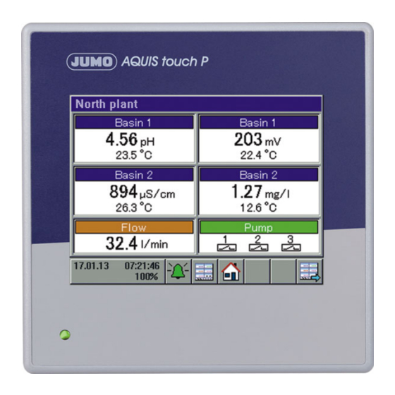
8 Operation 8.1.2 Display and control elements (4)(5) (7) (8) Touchscreen Toolbar with buttons for operation "Device menu" button with display of: • Date and time • Logged-in user ("Master" in the example) • Remaining memory display in percent for recording function (in the example: 100 %) "Alarm/Event List"... -
Page 76: Menu Structure
8 Operation 8.1.3 Menu structure At the operating level, 3 different navigation buttons are available to select ap- propriate screens for display and control of device functions. The "Device menu" and "Alarm/event list" menu levels are also displayed by means of corresponding buttons. The device menu contains submenus for set- ting, servicing, and diagnosing the device and its functions. - Page 77 8 Operation Overview of the menu structure Operating level Home Select Next operator operator display display Navigation in the operating loop Plug-in USB flash drive Device settings Memory Alarm-/ menue manager event list Secure hardware Login/logoff Alarm list remove Recorder Event list Calibration Update to USB...
- Page 78 8 Operation NOTE! The "Recorder Update to USB" and "Recorder Backup to USB" items appear in the "Memory Manager" menu only if the extra "Recording function" is en- abled. ⇨ Chapter 4.2 "Order details", page 22...
- Page 79 8 Operation Operation screens in the operation loop (16) (15) (14) (13) (12) (11) (10)
- Page 80 8 Operation Dia- Operator screen Description General screen 1 Freely configurable overview display of measuring values and digital sig- nal states General screen 2 The overviews can be configured as a 2-part screen or a 4-part screen. 2-part screen: Display of 2 primary and 2 secondary measured values per screen, 1 ad- ditional measured value and 3 binary values.
- Page 81 8 Operation Display of invalid values Invalid input signals/measured values or errors in the analog input configuration are detected and shown in the measured value displays as follows: Type of error Display underrange: measuring range underflow overrange: measuring range overflow Compensation error: An error occurred when compensat- ing for factors affecting the measurements of the analysis.
-
Page 82: Entry Of Text And Numbers
8 Operation 8.1.4 Entry of text and numbers Dialogs for entry of text or numbers appear automatically when the correspond- ing entry field is tapped. Text entry dialog There are 2 special features in addition to conventional entry of characters: •... - Page 83 8 Operation Number entry dialog This dialog opens if an entry field for numerical values is tapped. Special feature : The "Exp" button permits entry of an exponent as a power of ten. Procedure: Enter the numerical base value > Tap "Exp" > Enter the exponent > Confirm the entry Entry dialog buttons Explanation...
-
Page 84: Device Menu
8 Operation Device menu NOTE! Operation depends on the user's rights. Operating and setting options are re- stricted, depending on the user who is logged in. The "Master" and "Service" users have access to all menus and functions (de- fault setting). ⇨... - Page 85 No user level is configured at the factory. The user level must be configured and loaded into the device with the aid of the JUMO PC setup program. The "User Level" entry does not appear in the device menu as long as no user level is config- ured.
- Page 86 8 Operation To navigate in submenus, menu items are opened by tapping the folder icons identified with a plus sign. Open menu structures are identified with a minus sign and can be closed again by tapping the folder icon. Currently open windows can be left either by tapping "Exit" or the "Close win- dow"...
-
Page 87: Logon/Logoff
The logon/logoff dialog is open • The memory manager is open • During calibration of analysis sensors • During calibration of the touchscreen The re-authentication time is set using the JUMO PC setup program. ⇨ Chapter 21.8.3 "User list", page 292... -
Page 88: User Level
8.2.2 User level The user level consists of a user-defined list of parameters and configuration settings. You need the JUMO PC setup program to configure the user level. ⇨ Chapter 21.8.6 "User level", page 303 The user level can be opened from the device menu only if it has been config- ured beforehand with the aid of the PC setup program. -
Page 89: Functional Level
8 Operation 8.2.3 Functional level The functional level is used primarily for testing and diagnostic purposes. Analog and binary values of the outputs can be controlled manually here. This may be useful, for instance, for checking an individual piece of equipment in a plant. When performing maintenance and repair work, counters for operating hours, switching actions and flow rates can be reset. - Page 90 8 Operation Manual control of analog/digital outputs Activate the configuration setting "Enable menu mode" for the outputs you wish to control manually. "Manual mode buttons" buttons for manual control for these outputs then appear at the functional level. To adjust output values manually, proceed as follows: Select Device Menu >...
-
Page 91: Device Information
8 Operation 8.2.4 Device information For testing and diagnostic purposes, the "Device info" menu provides access to extensive data about the hardware and software of the device, as well as current analog and binary values. Device Info menu items: • General: Information about the main board, device software and Ethernet configuration •... -
Page 92: Service
Chapter 11.2 "Ci base calibration", page 188 • Digital sensor 1 to 6: For each digital JUMO sensor from the product group 2026xx that is operating on the device, a menu appears here that allows you to reset the calibration date of the sensor to the default settings. -
Page 93: Calibrating The Touchscreen
When the battery is empty a battery alarm will indicate that status. The battery must be exchanged before it is empty. The bat- tery must be exchanged by the JUMO Service department! In this case, send in the device! 8.2.6... - Page 94 Explanation Symbol linked Communication between the sensor electronics and the JUMO AQUIS touch P has been suc- cessfully established. The sensor is operating. Installation The device searches for the individual assign- ment table entry of a linkable sensor. A new sen-...
- Page 95 With the "Link" button, you can access the submenu for linking sensors that are not linked. Digital sensors from the JUMO prod- uct groups 2026xx must be linked by means of this button during startup.
- Page 96 In the list of detected sensors, highlight the one that you wish to link with the previously highlighted assignment table entry. JUMO sen- sors with digiLine electronics can be identified by the hardware ad- dress on the nameplate of the digiLine electronics. It is also displayed in the list of detected sensors and in the sensor informa- tion ("Info"...
- Page 97 8 Operation Bus status display The operating status of the digiLine bus is visualized in the title bar. The symbols used for this and their meaning are explained in the following table. Green There are no bus errors. All sensors are linked and functioning. This symbol appears in the title bar when connecting sensor electronics that have not yet been linked with the device.
-
Page 98: Alarm/Event List
8 Operation Alarm/Event list The JUMO AQUIS touch P offers the option of configuring alarm functions and event functions in numerous functions. In addition, the electronics of the JUMO AQUIS touch P are self-monitoring and trigger corresponding preprogrammed alarms and events in case the internal device malfunctions. -
Page 99: Alarm List
8 Operation 8.3.1 Alarm list The alarm list displays the current alarms. Alarms are cleared upon elimination of the alarm condition. Each alarm triggers a "collective alarm". The alarm list view contains buttons for viewing details about alarms and acknowledging col- lective and dosing alarms. - Page 100 8 Operation All alarms are available in the binary selector. In this way, digital outputs or other internal functions of the device can be controlled via alarms.
- Page 101 8 Operation Acknowledging collective/dosing alarms The collective alarm combines all alarms in the alarm list. It simplifies signaling of one or several active alarms with external indicating devices or to control rooms. The digital signal for the collective alarm is available in the binary selec- tor in 2 versions: •...
-
Page 102: Event List
8 Operation 8.3.2 Event list A number of situations that are essential for tracking and diagnostic purposes are logged in the event list. The entries are identified with corresponding icons on the basis of the type of event. In addition, events are logged with an icon in the data monitor/recording function. - Page 103 8 Operation The following table provides an overview of the possible entries in the event list. Events Symbol Power on Power off Alarm occurred Alarm cleared • Configured event (condition occurred) • Calibration start • Timer start • Wash contact start •...
-
Page 104: Memory Manager (Usb Flash Drive)
The measurement data are stored in DAT files and the configuration data in SET files. These files can be opened and evaluated with the aid of the JUMO PCA3000 evaluation software. Data that has been read out is marked inter- nally as retrieved and the available memory display is reset to 100 %. - Page 105 8 Operation PCA3000 evaluation software. In contrast to Recorder Update, there is no internal marking of recorder data and no resetting of the available memory display. NOTE! The "Recorder Update" and "Recorder Backup" functions are available only if the extra code "Recording" is enabled. NOTE! A measuring data recording session is closed by changing configuration data that are relevant to the data monitor or registration function (e.g.
- Page 106 Software Update: The device software can be updated with the aid of a USB flash drive. To do so, an appropriate update file must have been saved the flash drive in advance; this file can be obtained from JUMO Service. CAUTION! It is strongly recommended that the configuration and recorder data be backed prior to performing a software update.
-
Page 107: Operating The Controllers
8 Operation Operating the controllers NOTE! Since the automatic control mode is of prime importance in the case of control- lers, correct configuration of the individual controller and its parameterization (ad- justment of the control response) are very important for achieving good pro- cess value stability. -
Page 108: Automatic Control Mode
Setpoint 2 can be activated instead of Setpoint 1 in each controller by means of "Setpoint selection". Setpoints can also be specified by external sources and transmitted to the controllers in the JUMO AQUIS touch P via analog inputs. "Setpoint selection" and the configuration of external setpoints are set in the "Setpoint configuration". - Page 109 8 Operation On the operator screen of each controller, it is possible to change the current controller setpoint value, switch to the "Manual mode" or start "Self-optimiza- tion". Display of the digital controller output signals as indicator lights "Manual entry" button for changing the current setpoint value A change to the currently active setpoint value is transferred to the con- troller parameters.
-
Page 110: Controller In The Manual Mode
8 Operation 8.5.2 Controller in the manual mode In manual mode, the user can manually control the controller outputs. The controller outputs can be controlled in two ways: • Entry of a numerical value: Using the "Manual entry" button, the user can open a dialog to enter a fixed numerical value for the output. •... -
Page 111: Hold Mode
8 Operation 8.5.3 Hold mode The hold mode of a controller is activated in two ways: • Calibration of the actual-value input • Hold signal for the individual controller (specified in the controller configura- tion) In the hold mode, automatic control is suspended. The controller generates the preconfigured value as output level unless acceptance of the hold output is dis- abled in the configuration. -
Page 112: Optimizing Controllers
8 Operation 8.5.4 Optimizing controllers The control response can be optimized by entering known controller parameters manually or automatically by means of "self-optimization". During self-optimiza- tion, the individual controller determines the mathematical parameters for a pro- cess. The controller changes the output level (step change) and evaluates the response of the actual value in the process (step response). -
Page 113: Operation Of The Data Monitor/Recording Function
8 Operation Operation of the data monitor/recording function The standard version of the JUMO AQUIS touch P is equipped with a data mon- itor. It is used to record and view the analog measuring value and signal states of digital functions. Two groups are available, each of which can record up to 4 analog values and 3 binary values and display them in the form of a line recorder diagram. - Page 115 8 Operation Stylus trace view The "Next channel" button is used to scroll through the individual stylus trace views. For the particular channel selected, the appropriate scale with stylus trace appears in the stylus trace view. The position of the stylus corresponds to the current measured value of the channel.
- Page 116 8 Operation Scrolling through the stylus trace views The sequence of views that appear with repeated tapping of the "Next Channel" button can be seen in the graphic below. General line recorder screen Stylus trace view Stylus trace view Channel 4 Channel 1 Channel advance...
-
Page 117: History Function
8 Operation 8.6.2 History function The history function is available only in the recording function. It permits the user to view all recorded data in the ring memory on the device's display. The history is opened by tapping the "History" button on the operator screen for the respective group. -
Page 118: Online Visualization
⇨ Chapter 21.8.14 "Web server", page 331 The online visualization is open with a web browser. Enter either the IP address or the URL of the JUMO AQUIS touch P in the ad- dress bar of your web browser. ⇨... - Page 119 8 Operation The visualization displays a view identical in appearance to the device. A re- quest for a password appears next. The web server password specified in the web server configuration must be entered here. ⇨ Chapter 21.8.14 "Web server", page 331 As on the device, an operator screen can now be selected from the operation loop.
- Page 120 The open Quad View displays 4 plus signs for this purpose. Clicking on any one opens a request to enter the IP address of the JUMO AQUIS touch P. After the IP address has been entered, the selected view opens and can be con- trolled exactly as in the "Visualization"...
- Page 121 8 Operation Example of a Quad View:...
- Page 122 8 Operation...
-
Page 123: Parameterization
• Switch time hh:mm:ss Time to switch to standard time NOTE! The date and time are set in the online parameters in the JUMO PC setup pro- gram. v See chapter 21.10.1 "Date and time" Page 335... -
Page 124: Parameter Sets (Controller Parameter)
9 Parameterization Parameter Sets (Controller parameter) The parameters for the controller channels determine the control response of the individual control circuits. For stable control response, these parameters must be matched to the prevailing process conditions. Each controller channel has two parameter sets; the selection is made by means of a binary signal. "Pa- rameter set 1"... - Page 125 9 Parameterization Parameter Setting op- Explanation (Formula sym.) tions Switching peri- 0 to 9999 s If an output of a controller channel is con- od 1 figured as a Pulse length output, the period factory setting: between the switching pulses is fixed. 20.0 s The length of the switching period should be selected such that, on the one hand, the...
- Page 126 9 Parameterization Parameter Setting op- Explanation (Formula sym.) tions min. relay 0 to 60 s Depending on the Min. relay switch-on switch-on time 1 time, a lower limit is set for the pulse length factory setting: or an upper limit is set for the pulse fre- 0.0 s quency.
-
Page 127: Setpoint Values
9 Parameterization Setpoint values The "Setpoint values" submenu allows two setpoint values for each controller channel to be entered. As with the parameter sets, it is also possible to switch between setpoint values by means of a binary signal. "Setpoint value 1" is active by default.. - Page 128 9 Parameterization...
-
Page 129: Configuration
NOTE! Changes to the configuration settings described in this chapter can be made directly on the device or via the JUMO PC setup program. NOTE! Settings in the "Configuration" menu can be changed only if a user with corre- sponding user rights is logged in. -
Page 130: Basic Settings
0 to 100 % If the available memory display reaches this val- ue, the memory alarm is triggered. The following settings can be edited only with the aid of the JUMO PC setup program Setup quick info up to 20 text... -
Page 131: Display
10 Configuration 10.3 Display 10.3.1 Generally Open: Device Menu > Configuration > Display > General Configuration point Selection/ Explanation setting option Lock touchscreen Selection from Digital signal that blocks operation of the touch- binary selector screen (e.g. key switch for locking operation) Simulation of When this function is activated, alternating on/off inputs... -
Page 132: Screen
10 Configuration 10.3.2 Screen Open: Device Menu > Configuration > Display > Screen Configuration item Selection/ Explanation setting option Activation of screen- inactive Type of screensaver activation saver time to switch off control signal Wait time for screen- 10 to 32767 s only with activation of the screensaver after saver wait time:... -
Page 133: Operating Loop
10 Configuration 10.4 Operating loop 10.4.1 General screens Open: Device Menu > Configuration > Operation Loop > General Screen > General Screen 1 to 2 Configuration point Selection/ Explanation setting option Gener. screen type 2-part screen Selection of the type of overview screen; 4-part screen 2-part screen: Display of 2 main values, 2 sec- ond values, 1 additional value and 3 binary val-... -
Page 134: Detailed Screens
10 Configuration 10.4.2 Detailed screens Open: Device menu > Configuration > Operation Loop > Individual screen > Individual screen 1 to 6 Configuration point Selection/ Explanation setting option Screen title up to 31 text characters Title of the individual screen Input signal main val- Selection from Signal source of the analog value displayed as... -
Page 135: Analog Inputs
Each value pair assigns a display value (Y-column) to a measuring value (X-column). Up to 8 linearization tables can be stored. To cre- ate a linearization table, you need the JUMO PC setup program. Start of -99999 to +99999... - Page 136 10 Configuration Configuration point Selection/ Explanation setting option 0 to 99999 Ω only for IN 5: Resistance value between the slid- er (S) and start point (A) in a resistance transmit- ter/potentiometer when the slider is at the start point. 6 to 99999 Ω...
-
Page 137: Universal Inputs Of Base Unit And Optional Boards
10 Configuration 10.5.2 Universal inputs of base unit and optional boards Base unit universal input: IN 6 Optional board universal inputs: IN 11/12 Open: Device Menu > Configuration > Analog Inputs > Universal Input 1 to 3 > Configuration Configuration point Selection/ Explanation setting option Description... - Page 138 Each value pair assigns a display value (Y-column) to a measuring value (X-column). Up to 8 linearization tables can be stored. To cre- ate a linearization table, you need the JUMO PC setup program. Unit up to 5 text characters...
- Page 139 10 Configuration Configuration point Selection/ Explanation setting option 6 to 4000 Ω only for IN 11/12: Span of the variable resistance value between the slider (S) and start point (A) 0 to 4000 Ω only for IN 11/12: Resistance value between the slider (S) and end point (E) in a resistance poten- tiometer when the slider is at the end point.
-
Page 140: Ph/Redox/Nh Analysis Inputs
10 Configuration 10.5.3 pH/Redox/NH analysis inputs Open: Device Menu > Configuration > Analog Inputs > Analysis Input 1 to 4 > Configuration Configuration point Selection/ Explanation setting option Description up to 15 text characters Designation for the input Electrode type pH standard Type of electrode connected pH antimony... - Page 141 10 Configuration Configuration point Selection/ Explanation setting option Text sensor alarm up to 21 text characters Text for the alarm/event list in case of sensor er- Alarms 1/2 Analog input alarms are used to monitor measured values in relation to adjustable limit values. The alarm settings for all analog device functions are explained together.
-
Page 142: Cr/Ci Analysis Inputs (Conductive/Inductive Conductivity)
10 Configuration 10.5.4 CR/Ci analysis inputs (conductive/inductive conductivity) Open: Device Menu > Configuration > Analog Inputs > Analysis Input 1 to 4 > Configuration Configuration point Selection/ Explanation setting option Description up to 15 text characters Designation for the input Compensation tem- Selection from Analog input of the compensation thermometer... -
Page 143: Cr/Ci Measuring Ranges
10 Configuration Configuration point Selection/ Explanation setting option Measuring ranges Four ranges each can be configured for conduc- 1 to 4 tive/inductive (CR/Ci) conductivity measure- ments. The settings for all CR-/Ci analysis inputs are explained together. ⇨ "CR/Ci measuring range configuration", page Alarms 1/2 Analog input alarms are used to monitor measured values per measuring range... - Page 144 10 Configuration CR/Ci measuring range configuration Open: Device Menu > Configuration > Analog Inputs > Analysis Input 1 to 4 > Measuring Range 1 to 4 Configuration point Selection/ Explanation setting option TDS factor 0.01 to 2.00 only for conductive conductivity with TDS compensation: Conversion factor from measured conductivity to display unit (see configuration item "Unit"...
- Page 145 Each value pair assigns a display value (Y-column) to a measuring value (X-column). Up to 8 linearization tables can be stored. To cre- ate a linearization table, you need the JUMO PC setup program. Start of -99999 to +99999...
-
Page 146: Analog Outputs Of Base Unit And Optional Boards
10 Configuration 10.6 Analog outputs of base unit and optional boards Open: Device Menu > Configuration > Analog Outputs > Analog Output 1 to 9 Configuration point Selection/ Explanation setting option Description up to 15 text characters Designation for the output Signal Selection from Analog signal source of the output... -
Page 147: Digital Inputs Of Base Unit And Optional Boards
10 Configuration Configuration point Selection/ Explanation setting option Response at hold Specification of the analog output value when the high hold function is activated, during calibration of NAMUR low one of the sensors for the particular output or at NAMUR high error (overrange/underrange) hold safety value... -
Page 148: Digital Outputs Of Base Unit And Optional Boards
10 Configuration 10.8 Digital outputs of base unit and optional boards Open: Device Menu > Configuration > Digital Outputs > Digital Output 1 to 17 Configuration point Selection/ Explanation setting option Description up to 21 text characters Designation for the output Signal Selection from Digital signal source for the output... -
Page 149: Digital Sensors
10.9 Digital sensors NOTE! For operation of digital sensors, you need the extra code "JUMO digiLine pro- tocol activated“ (see Chapter 4.2 "Order details", page 22) NOTE! Only one serial interface of the device can be configured for operation of digital sensors. -
Page 150: Configuration
The alarm settings for all analog device functions are explained together. ⇨ Chapter 10.10.2 "Alarms for analog signals and digital sensors", page Only for JUMO sensors with digiLine electronics pH/ORP/T Configuration point Selection/ Explanation setting option TAG checking... - Page 151 Sensor temperature: The integrat- ed temperature probe of the pH sen- sor supplies the compensation temperature. Interface: The AQUIS touch P trans- mits the compensation temperature to the digiLine electronics via the se- rial interface. The source of the com- pensation temperature is set in the configuration point "Compensation...
- Page 152 Sensor temperature: The integrat- ed temperature probe of the O-DO sensor supplies the compensation temperature. Interface: The AQUIS touch P trans- mits the compensation temperature to the sensor electronics via the inter- face. The source of the compensa- tion temperature is set in the configuration point "Compensation...
- Page 153 10 Configuration Configuration point Selection/ Explanation setting option Start of display range -99999 to +99999 Upper/lower limit for labeling the scale when displaying measured val- Display range end -99999 to +99999 ues, e.g. in recorder diagrams and bar graphs Sampling rate 1 to 999 s Indication of the length of the interval between 2 measurements...
- Page 154 10 Configuration For JUMO NTU sensors only Configuration point Selection/ Explanation setting option Turbidity measuring automatic Selection of the measuring range for range 0 to 50 NTU the turbidity measurement 0 to 200 NTU 0 to 1000 NTU The user can choose a fixed measur-...
-
Page 155: Sensor Alarms
JUMO AQUIS touch P. The settings for the alarm conditions themselves are made in the configuration of the individual sensor electronics or stipulated by the specifications for the particular sensor. - Page 156 Alarm for sensor calibration due (see "Calibration data" in the JUMO digiLine pH operating manual) CIP/SIP/Autoclaving warning Pre-alarm for maximum number of CIP/SIP/autoclaving cycles (see "Sensor monitoring" in the JUMO digiLine pH operating manual) CIP/SIP/Autoclaving alarm Alarm for maximum number of CIP/SIP/autoclaving cy- cles (see "Sensor monitoring"...
- Page 157 Alarm for redox value out of range Calibration timer alarm Alarm for sensor calibration due (see "Calibration data" in the JUMO digiLine ORP operating manual) Digital input state Signal state of the digital input of the sensor electronics JUMO digiLine T...
-
Page 158: Cip/Sip Definition (Jumo Digiline Ph Only)
0 to 9999 days Time from one calibration to the next. When a calibration is due is indicated by the calibration alarm on the JUMO AQUIS touch P. Further- more, the calibration alarm can be queried via the Modbus. This setting is saved in the configuration of the digiLine electronics. -
Page 159: Limit Monitoring And Alarms
10 Configuration 10.10 Limit monitoring and alarms 10.10.1 Limit value monitoring Open Limit Monitoring: Device Menu > Configuration > Limit Monitoring > Limit Monitoring 1 to 8 Configuration point Selection/ Explanation setting option Description up to 21 text characters Designation for the limit monitoring Input signal Selection from Signal source of the analog value that is... - Page 160 10 Configuration Configuration point Selection/ Explanation setting option Response at hold inactive Specification of the alarm state when the hold active function is activated, at calibration of the particu- hold lar input or at error (out of range) Response at inactive inactive: alarm suppressed calibration...
- Page 161 10 Configuration Minimum alarm (On-signal when value drops below lower limit) Binary value Hysteresis Input signal Limit value Maximum alarm(On-signal when value exceeds upper limit) Binary value Hysteresis Input signal Limit value Alarm window (On-signal within a configurable value range Binary value Hysteresis...
-
Page 162: Digital Signal Alarms
10 Configuration 10.10.3 Digital signal alarms Open: Device Menu > Configuration > Digital Inputs > Digital Input 1 to 9 Configuration point Selection/ Explanation setting option Digital signal for hold Selection from the Digital signal for activating the hold function binary selector When the hold function is activated, the alarm as- sumes the state defined in the "Response at... -
Page 163: Calibration Timer
10 Configuration 10.11 Calibration timer Every analysis input and universal input has its own calibration timer. Calibration timers signal when sensor calibration is due. Once a particular input has been calibrated successfully, its calibration timer is reset. The signal can be generat- ed, for instance, by digital outputs, external indicator lights or the alarm/event list. -
Page 164: Controller
10 Configuration 10.12 Controller 10.12.1 Configuration of the controllers Open: Device Menu > Configuration > Controller > Controller 1 to 4 > Configu- ration Configuration point Selection/ Explanation setting option Controller type Two-point controller Selection of controller type Three-state controller, Coarse-/fine controller, Modulating controller, Proportional controller... - Page 165 10 Configuration Configuration point Selection/ Explanation setting option Man. output level 2 0 to 100 % only for coarse/fine controllers: Preconfigured Man. output level for the 2nd con- troller output Accepted automatically upon activation of the manual mode if acceptance of the manual output level is set to "Yes";...
- Page 166 10 Configuration Configuration point Selection/ Explanation setting option Alarm ack. Inactive Activation/deactivation of the acknowledgment Active function Dosing alarms of the respective controller must be acknowledged in the "Alarm list" when "Alarm acknowledgement" is activated. Dosing alarms are not cleared automatically when the control deviation drops to a value that is less than or equal to the alarm tolerance.
- Page 167 For more detailed information on the subject of control technology, you can download the technical article "Control technology - Basic principles and tips for the practitioner" (FAS 525) as a PDF document for free from the JUMO website.
-
Page 168: Controller Inputs
10 Configuration 10.12.2 Controller inputs Open: Device Menu > Configuration > Controller > Controller 1 to 4 > Input Configuration point Selection/ Explanation setting option Description up to 15 text characters Designation of the controller input Actual value Selection from Selection of the analog signal source for the ac- Analog selection tual value... -
Page 169: Disturbance Feedforward Control
10 Configuration 10.12.3 Disturbance feedforward control Open: Device Menu > Configuration > Controller > Controller 1 to 4 > Ena. variable disturbance Configuration point Selection/ Explanation setting option additive var. disturb. Selection from Analog input for the additive variable disturbance Analog selection The additive output level component added. -
Page 170: Self-Optimization
10 Configuration Configuration point Selection/ Explanation setting option Multiplicative Selection from Analog input for the multiplicative variable distur- Disturbance Analog selection bance The ratio of the variable disturbance value at the working point of the variable disturbance is multi- plied by the proportional gain of the controller. Changes in the variable disturbance affect the total gain of the controller. -
Page 171: Setpoint Value Configuration
10 Configuration 10.13 Setpoint value configuration Open: Device Menu > Configuration > Setpoint Value Configuration > Setpoint Value Configuration Controller 1 to 4 Configuration point Selection/ Explanation setting option external Selection from Selection of the analog value as setpoint value Setpoint 1 to 2 Analog selection source... -
Page 172: Timers
10 Configuration 10.14 Timers Open timer: Device Menu > Configuration > Timer > Timer 1 to 10 > Timer Configuration point Selection/ Explanation setting option Timer function Inactive Operating principle of the timer Timers Control timer Control timer: Functions as weekly time switch Settings for a time program during the week ⇨... - Page 173 10 Configuration Configuration point Selection/ Explanation setting option Signal Selection from Selection of an analog signal the deviation of Tolerance band x Analog selection which from the "Tolerance band w signal" is to be monitored The timer starts and continues running only if the amount of deviation is not greater than the set window range.
-
Page 174: Control Timer
10 Configuration Timing diagram Timer start Timer time After-run time delay Timer end Timer start Timer time After-run time delay Timer end Signal Timer start Output signal After-run time Timer 10.14.1 Control timer Timer settings for a timed program during the week Prerequisite: The "Timer function"... -
Page 175: Washtimer
10 Configuration 10.15 Washtimer Open: Device Menu > Configuration > Washtimer > Washtimer 1 to 2 Configuration point Selection/ Explanation setting option Washtimer active Activation/deactivation of the washtimer Washtimers are used to clean analysis sensors regularly and can actuate external equipment for cleaning sensors via digital outputs. -
Page 176: Counters
10 Configuration 10.16 Counters Open: Device Menu > Configuration > Counter > Counter 1 to 4 Configuration point Selection/ Explanation setting option Function Inactive Counter operation mode Service count. Operating hours counter Service count.: The positive edges (switch-on operations) of a digital signal are counted (E.g. -
Page 177: Ethernet
JUMO AQUIS touch P is connected. To enter an IP configuration manually for the JUMO AQUIS touch P, a valid available IP address in the network must be known. Please contact your network administrator in this regard. -
Page 178: Serial Interfaces
(see order details for extra code "JUMO digiLine protocol activated") In the JUMO AQUIS touch P, either the inter- face on the base unit or the optional serial in- terface (if present) can be configured for digital sensors (digiLine operation). -
Page 179: Formula
10 Configuration 10.19 Formula Mathematical formula are created with the JUMO PC setup program and loaded to the device. Following this, the configuration of a mathematical for- mula can also be edited directly on the device. Open: Device Menu > Configuration > Mathematical Formula > Formula 1 to 8... -
Page 180: Logic Formula
10 Configuration 10.20 Logic formula Logic formula are created with the JUMO PC setup program and loaded to the device. Following this, the configuration of a logic formula can also be ed- ited directly on the device. Open: Device Menu > Configuration > Logic Formula > Formula 1 to 30... -
Page 181: External Analog Inputs
10 Configuration 10.22 External analog inputs Open: Device Menu > Configuration > External Analog Inputs > External Analog Inputs 1 to 8 Configuration point Selection/ Explanation setting option Description up to 15 text characters Designation of the external analog input Temperature None For automatic conversion of temperature units, it... -
Page 182: External Digital Inputs
10 Configuration 10.23 External digital inputs Open: Device Menu > Configuration > External Digital Inputs > External Digital Inputs 1 to 8 Configuration point Selection/ Explanation setting option Description up to 15 text characters Designation of the external digital input Hold value Nonvolatile storage of the last analog value re- ceived when the device restarts... - Page 183 10 Configuration Configuration point Selection/ Explanation setting option K-factor 0 to. 99999 l Ratio of the pulse count to flow rate (pulses per liter) The K-factor can be obtained from the documen- tation for the fitting in which the flow rate sensor (e.g.
- Page 184 10 Configuration Configuration point Selection/ Explanation setting option Total quantity only available with flow measurement activat- hourly daily Activation of the flow rate quantity counter weekly monthly The setting establishes the automatic reset cy- annually cle. unlimited In addition, the flow rate quantity counters can be reset manually at the functional level or via a dig- ital signal (reset input).
-
Page 185: Retrofitting Optional Boards
11 Retrofitting optional boards 11.1 Inserting optional boards DANGER! Insertion and removal of optional boards must be performed only by qualified personnel. To ensure electrical safety, country-specific regulations must be ob- served. The following step-by-step table explains in detail the procedure for retrofitting optional boards: Step Action... - Page 186 11 Retrofitting optional boards Step Action Disconnect all screw terminals and interface cables connected at the rear of the device. To prevent connections being interchanged, note down the assignment of the connectors to the sockets. Undo (do not remove) the two countersunk screws on the bottom of the case and remove the pan head screw on the side of the case.
- Page 187 11 Retrofitting optional boards Step Action Insert the optional board in the selected slot. Ensure that the board is seated correctly. Fill all empty slots with plastic board frames. Re-insert the rear panel of the case and fasten with 3 screws. Make sure that all the toothed lock washers for securing the screws are re-inserted (see Step 4).
-
Page 188: Ci Base Calibration
When the battery is empty a battery alarm will indicate that status. The battery must be exchanged before it is empty. The bat- tery must be exchanged by the JUMO Service department! In this case, send in the device! - Page 189 The default settings authorize the "Master" and "Service" users for this. v Chapter 8.1.1 "Passwords and user rights", Page 73 Ensure that the electronics of the JUMO AQUIS touch P have reached operating temperature. You can view the board tempera- ture at: Device Menu r Service r Service Data r "Internal Data"...
- Page 190 11 Retrofitting optional boards Step Action Place the wire of the calibration sensor with 2 windings through the opening in the Ci sensor without connecting the ends of the wires. Start the Ci base calibration Device Menu r Service r Ci Base Calibration IN 7 to 8 Enter the cell constant for the sensor and confirm by pressing "OK".
- Page 191 11 Retrofitting optional boards Step Action Connect the ends of the wires forming the conductor loop of the calibration adapter. Set the calibration adapter to the resistance value shown in the in- struction text in the display (in the example: 20kΩ). Once the mea- surement displayed has stabilized, confirm by pressing "OK".
- Page 192 11 Retrofitting optional boards Step Action Once all measurings have been confirmed, a summary of the cali- bration data acquired appears. Confirm by pressing "OK". If the Ci base calibration fails, the procedure is canceled without acceptance of the calibration data. Protocol after successful Ci base calibration...
-
Page 193: Calibration In General
12 Calibration in general 12.1 Notes WARNING! During the calibration, the relays and analog output signals assume the config- ured states! 12.2 General information The actual electrical characteristics of analysis sensors always deviate some- what from the nominal specifications. The reasons for this include: •... - Page 194 12 Calibration in general • You must be logged in as a user with the right to perform calibrations. Fac- tory-preset users have all of these rights. v „Passwords and user rights“, Page 73 • You must ensure that the calibration default settings for the individual analy- sis inputs and, possibly, the universal inputs are set correctly.
-
Page 195: Calibration Logbook
12 Calibration in general 12.3 Calibration logbook A separate logbook is maintained for each analysis and universal input. The last 10 successful calibrations of the input concerned are saved in the cal- ibration logbook. Canceled or failed calibrations (calibrations outside the per- missible limits) are not saved in the logbook, but rather noted in the event list. - Page 196 Tapping the "Details" button opens the selected logbook entry in the detail view. The detail view displays a table with all calibration values from a calibration pro- cedure. The "Service" button is used for diagnostic purposes by trained person- nel or JUMO Service.
- Page 197 12 Calibration in general Assessment criteria pH calibrations (glass electrodes and ISFET connected to analysis measuring inputs as well as standard sig- nals connected to universal inputs) Calibration value [unit] — — < ≤ < < ≤ < Zero point [pH] 6 to 8 <...
- Page 198 12 Calibration in general Calibration of conductivity sensors (analysis measuring inputs and standard signals connected to universal inputs) Calibration value [unit] — — < ≤ < < ≤ 150 < Rel. cell constant (CR) [%] 75 to 125 < ≤ <...
-
Page 199: Calibrating A Ph Measuring Chain
The three- point calibration can be performed only for pH sensors on analysis inputs. It is not available for JUMO digiLine pH sensors. This method requires 3 buffer solutions with defined pH-values as references. -
Page 200: Calibration Default Settings For Ph Sensors
13 Calibrating a pH measuring chain 13.2.2 Calibration default settings for pH sensors Before you can perform a calibration, you must first enter the necessary calibra- tion default settings. The possible settings for the pH Calibration are described in the following. Open the calibration default settings: Device Menu >... - Page 201 "pH buf- preferably for calibrating and fer 1 to 3" are hidden. adjusting technical pH mea- You need the JUMO PC setup program suring instruments acc. to DIN to edit buffer set tables. 19267...
- Page 202 13 Calibrating a pH measuring chain Parameters Possible settings Explanation Temperature com- Selection from Analog selection Temperature input for automatic sens- pensation ing of the test/sample solution tempera- ture during the calibration...
-
Page 203: Ph Calibration Routines
Device Menu > Calibration > Select Analysis Input for pH/redox/ > Open Zero-Point Calibration for pH sensors with JUMO digiLine electronics: Device Menu > Calibration > Digital Sensor 1 to 6 > Open Zero- Point Calibration... - Page 204 13 Calibrating a pH measuring chain Step Action Entry of the pH-value of the buffer solution • without buffer recognition: Check whether the "pH buffer 1" matches the pH-value of the buffer solution used. If a buffer set table was not specified, the "buffer 1 pH"...
-
Page 205: Two-Point And Three-Point Calibration
Device Menu > Calibration > Analysis Input Select Analysis Input for pH/redox/NH > Open Two-Point or Three-Point Calibration for pH sensors with JUMO digiLine electronics: Device Menu > Calibration > Digital Sensor 1 to 6 > Open Two- Point Calibration... - Page 206 13 Calibrating a pH measuring chain Step Action Entry of the pH-value of the buffer solution • without buffer recognition: Check whether the "pH buffer 1" matches the pH-value of the buffer solution used. If a buffer set table was not specified, the "buffer 1 pH"...
-
Page 207: Calibrating Redox Sensors
14 Calibrating redox sensors 14.1 Important information WARNING! During the calibration, the relays and analog output signals assume the config- ured states! 14.2 General information The calibration of Redox sensors is based on measurements in test solutions with a defined Redox potential. 14.2.1 Calibration methods for Redox sensors Zero-point calibration... -
Page 208: Calibration Default Settings For Redox Sensors
14 Calibrating redox sensors 14.2.2 Calibration default settings for Redox sensors Before you can perform a calibration, you must first enter the necessary calibra- tion default settings. The possible settings for the Redox calibration are de- scribed in the following. Open the calibration default settings: Device Menu >... -
Page 209: Redox Calibration Routines
Device Menu > Calibration > Select Analysis Input for pH/redox/ > Zero-Point Calibration for redox sensors with JUMO digiLine electronics: Device Menu > Calibration > Digital Sensor 1 to 6 > Zero-Point Calibration Check that the "Redox test solution" value displayed matches the Redox value of the test solution. - Page 210 14 Calibrating redox sensors Step Action Press "Yes" to accept the Calibration values determined and enter the Calibration in the Calibration logbook. Press "No" to discard the results.
-
Page 211: Two-Point Calibration
Device Menu > Calibration > Select Analysis Input for pH/redox/ > Two-Point Calibration for redox sensors with JUMO digiLine electronics: Device Menu > Calibration > Digital Sensor 1 to 6 > Two-Point Calibration Enter the concentration value of the first reference solution in per- cent. - Page 212 14 Calibrating redox sensors...
-
Page 213: Calibrating Ammonia Sensors
15 Calibrating ammonia sensors 15.1 Notes WARNING! During the calibration, the relays and analog output signals assume the config- ured states! 15.2 General information The calibration of ammonia sensors is based on measurements in ammonia- free test solutions. 15.2.1 Calibration methods for ammonia sensors Zero-point calibration This calibration method is used to determine the ammonia zero point. -
Page 214: Ammonia Calibration Routines
15 Calibrating ammonia sensors 15.3 Ammonia calibration routines NOTE! You must be logged in with corresponding user rights to perform calibrations. v Chapter 8.2.1 "Logon/Logoff", Page 87 15.3.1 Zero-point calibration Step Action Start the Zero-point calibration. Device menu r Calibration r Select Analysis Input for pH/Redox/ r Zero-Point Calibration Clean the ammonia electrode and immerse it in the ammonia-free test solution. -
Page 215: Calibrating Cr Conductivity Sensors
16 Calibrating CR conductivity sensors 16.1 Notes WARNING! During the calibration, the relays and analog output signals assume the config- ured states! 16.2 General information The calibration of CR sensors is based on measurements in test solutions with a defined electrolytic conductivity. Since the electrolytic conductivity of liquids is temperature dependent, the temperature of the test solution must be sensed. -
Page 216: Calibration Default Settings For Cr Conductivity Sensors
16 Calibrating CR conductivity sensors 16.2.2 Calibration default settings for CR conductivity sensors Before you can perform a calibration, you must first enter the necessary calibra- tion default settings. The possible settings for the CR calibration are described in the following. Open the calibration default settings: Device menu r Calibration r Select CR Analysis Input r Calibration Default Settings... - Page 217 16 Calibrating CR conductivity sensors Calibration default settings for calibrating the relative cell constant Parameter Setting options Explanation Reference conductivi- 0 to 9999 mS/cm Conductivity of the reference solution Calibration default settings for calibrating the temperature coefficient Parameter Setting options Explanation Temperature com- Selection from...
-
Page 218: Cr Calibration Routines
16 Calibrating CR conductivity sensors 16.3 CR calibration routines NOTE! Conductivity measuring inputs can be configured with measuring range change- over. Accordingly, calibrations must be performed for all "accessible measuring ranges". NOTE! You must be logged in with corresponding user rights to perform calibrations. v Chapter 8.2.1 "Logon/Logoff", Page 87 16.3.1 Calibrating the relative cell constant... - Page 219 16 Calibrating CR conductivity sensors Step Action Ensure that • the sensor has been cleaned and is immersed in the test solu- tion, • the set reference conductivity matches the conductivity value of the test solution. Wait until the measuring value displayed stabilizes and then con- firm the result of the measurement by pressing "OK".
-
Page 220: Calibrating The Temperature Coefficient
16 Calibrating CR conductivity sensors 16.3.2 Calibrating the temperature coefficient Step Action Start calibration of the temperature coefficient. Device menu r Calibration r Select CR Analysis Input r TC Cal- ibration Clean the sensor and immerse it in the sample solution. Ensure that the rel. - Page 221 16 Calibrating CR conductivity sensors Step Action • with temperature sensing A prerequisite is that temperature compensation was specified in the calibration default settings. Bring the temperature of the sample solution to the requested val- ues of the reference and operation temperatures in succession. The order does not matter.
- Page 222 16 Calibrating CR conductivity sensors...
-
Page 223: Calibrating Ci Conductivity Sensors
17 Calibrating Ci conductivity sensors 17.1 Important information WARNING! During the calibration, the relays and analog output signals assume the config- ured states! 17.2 General information The calibration of Ci sensors is based on measurements in test solutions with a defined electrolytic conductivity. -
Page 224: Calibration Default Settings For Ci Conductivity Sensors
17 Calibrating Ci conductivity sensors TC curve (for nonlinear temperature coefficients) If the conductivity of a liquid whose temperature coefficient changes with tem- perature has to be measured, this method can determine 5 temperature coeffi- cients for 5 temperature intervals. In this way, it is possible to determine a good approximation of the temperature coefficient curve. - Page 225 17 Calibrating Ci conductivity sensors Sample screen: Ci calibration default settings The calibration default settings enable the calibration routines to be accessed in the particular calibration menu. Calibration routines that are not enabled are not visible in the calibration menu. Additional calibration default settings are explained in the following table.
- Page 226 17 Calibrating Ci conductivity sensors Calibration default settings for calibrating the TC curve Parameter Setting options Explanation Temperature com- Selection from Temperature input for automatic sensing of the test/ pensation analog selection sample solution temperature during the calibration Starting temperature -50 to 250 °C The starting and final temperatures of the range for which a temperature coefficient curve is to be deter-...
-
Page 227: Ci Calibration Routines
17 Calibrating Ci conductivity sensors 17.3 Ci calibration routines NOTE! Conductivity measuring inputs can be configured with measuring range change- over. Accordingly, calibrations must be performed for all "accessible measuring ranges". NOTE! You must be logged in with corresponding user rights to perform calibrations. v Chapter 8.2.1 "Logon/Logoff", Page 87 NOTE! Analysis inputs for inductive conductivity measurements (Ci) must undergo a... - Page 228 17 Calibrating Ci conductivity sensors Step Action Ensure that • the sensor has been cleaned and is immersed in the test solu- tion, • the set reference conductivity matches the conductivity value of the test solution. Wait until the measuring value displayed stabilizes and then con- firm the result of the measurement by pressing "OK".
-
Page 229: Calibrating The Temperature Coefficient
17 Calibrating Ci conductivity sensors 17.3.2 Calibrating the temperature coefficient Step Action Start calibration of the temperature coefficient. Device Settings Menu r Calibration r Select Ci Analysis Input or Universal Input r TC Calibration Clean the sensor and immerse it in the sample solution. Ensure that the rel. - Page 230 17 Calibrating Ci conductivity sensors Step Action • with temperature sensing A prerequisite is that temperature compensation was specified in the calibration the default settings. Bring the temperature of the sample solution to the requested val- ues of the reference and operation temperatures in succession. The order does not matter.
-
Page 231: Calibrating The Tc-Curve
17 Calibrating Ci conductivity sensors 17.3.3 Calibrating the TC-Curve Step Action Start the desired calibration of the TC-Curve. Device Menu r Calibration r Analysis Input 1 to 4 (Ci) and/or Universal Input 1 to 3 r TC-Curve Clean the sensor and immerse it in the sample solution. Ensure that the rel. - Page 232 17 Calibrating Ci conductivity sensors...
-
Page 233: Calibrating Universal Inputs
18 Calibrating universal inputs 18.1 Important information WARNING! During the calibration, the relays and analog output signals assume the config- ured states! 18.2 General information 18.2.1 Calibration methods for universal inputs Universal inputs can be configured with various operation modes for a number of different process variables (see table below). - Page 234 18 Calibrating universal inputs Two-point calibration The zero point and slope of the measuring characteristic curve are determined with the aid of 2 measurings of 2 different reference solutions. Two test solutions with defined values of the respective process variable are needed as a references.
-
Page 235: Universal Inputs Calibration Default Settings
18 Calibrating universal inputs 18.2.2 Universal inputs calibration default settings The calibration default setting available for selection depends on the configura- tion settings of the universal input. Open the calibration default settings: Device Menu r Calibration r Select Universal Input r Calibration Default Settings Calibration default settings for the individual operation modes •... - Page 236 18 Calibrating universal inputs • free chlorine, ph/Temp.-compensated In the universal inputs calibration default settings for the "free chlorine, ph/T- compensated" operation mode, the slope calibration is enabled and pre-config- ured as the only available calibration routine. Sample screen: Universal input calibration default settings in the "free chlorine, pH/T-com- pensated"...
-
Page 237: Universal Input Calibration Routines
18 Calibrating universal inputs 18.3 Universal input calibration routines This chapter explains the universal inputs calibration routines for the "linear scal- ing" and "free chlorine, ph/T-compensated" operation modes. The explanations in the corresponding calibration chapters for the "pH value measurement" and "Conductivity measurement" operation modes apply, except that three-point calibration for pH sensors is not available for universal inputs (see Chapter 18.2.1 "Calibration methods for universal inputs", Page 233). -
Page 238: Zero Point/Slope Calibration (Linear Scaling)
18 Calibrating universal inputs 18.3.1 Zero point/slope calibration (linear scaling) Step Action Start the desired Calibration routine. Device Menu r Calibration r Select Universal Input r Zero-point calibration Clean the sensor and immerse it in the test solution. Wait until the measured value displayed stabilizes and then confirm the result of the measurement by pressing "OK". -
Page 239: Two-Point Calibration (Linear Scaling)
18 Calibrating universal inputs 18.3.2 Two-point calibration (linear scaling) Step Action Start the desired Calibration routine. Device Menu r Calibration r Select Universal Input r Two-point calibration Clean the sensor and immerse it in the first test solution. Wait until the measuring value displayed stabiliz- es and then confirm the result of the measurement by pressing "OK". - Page 240 18 Calibrating universal inputs...
-
Page 241: Slope Calibration (Free Chlorine, Ph/Temp.-Compensated)
18 Calibrating universal inputs 18.3.3 Slope calibration (free chlorine, ph/Temp.-compensated) Step Action Start the slope calibration. Device Menu r Calibration r Select Universal Input r Slope Cal- ibration Clean the sensor and immerse it in the test solution. Check the displayed values for the pH value and temperature. - Page 242 18 Calibrating universal inputs Step Action Press "Yes" to accept the Calibration values determined and enter the Calibration in the Calibration logbook. Press "No" to discard the results.
-
Page 243: Calibrating O-Do Sensors
19 Calibrating O-DO sensors 19.1 Important information WARNING! During the calibration, the relays and analog output signals assume the config- ured states! 19.2 General information Depending on the calibration method, O-DO sensors are calibrated on the basis of measurements in water and water sulfite solutions (sulfite concentration <... -
Page 244: Calibration Methods For O-Do Sensors
19 Calibrating O-DO sensors 19.2.1 Calibration methods for O-DO sensors End value calibration With end value calibration, the slope of the sensor is calibrated beyond the de- fined state of 100 % oxygen saturation. This state can in principle be achieved in two ways: •... - Page 245 Temperature input: The integrated temperature probe of the O-DO sensor supplies the compensation tempera- ture. Interface: The AQUIS touch p transmits the compensation temperature to the sensor electronics via the interface. The source of the compensation tempera- ture is set in the configuration point "Compensation temperature".
-
Page 246: O-Do Calibration Routine
19 Calibrating O-DO sensors 19.3 O-DO calibration routine NOTE! You must be logged in with corresponding user rights to perform calibrations. ⇨ Chapter 8.2.1 "Logon/Logoff", page 87 19.3.1 End value calibration Step Action Start the end value calibration. Device Menu > Calibration > Digital Sensor 1 to 6 > End Value Calibration If temperature compensation was not specified in the calibration default settings, enter the temperature of the air-saturated water or... - Page 247 19 Calibrating O-DO sensors Step Action The device displays the current measured value of oxygen satura- tion and the test material temperature. The setpoint value for oxy- gen saturation (100 %Sat) is set automatically by the device. The user does not need to make any entries here. Wait until the measured value displayed stabilizes and then con- firm the result of the measurement by pressing "OK"...
-
Page 248: Two-Point Calibration
19 Calibrating O-DO sensors 19.3.2 Two-point Calibration Step Action Start the two-point calibration. Device Menu > Calibration > Digital Sensor 1 to 6 > Two-Point Calibration To determine the zero point, prepare a water sulfite solution (sulfite concentration < 2 %). If temperature compensation was not specified in the calibration default settings, enter the temperature of the test materials used here manually. - Page 249 19 Calibrating O-DO sensors Step Action Immerse the sensor in air-saturated water or position it in water va- por-saturated air (see Chapter 19.2.1 "Calibration methods for O- DO sensors", page 244). If you use water vapor-saturated air, en- sure constant air pressure, constant temperature and that no water drops adhere to the membrane during the calibration procedure.
- Page 250 19 Calibrating O-DO sensors...
-
Page 251: Calibrating Turbidity Sensors
20 Calibrating turbidity sensors 20.1 Important information WARNING! During the calibration, the relays and analog output signals assume the config- ured states! 20.2 General information Turbidity sensors are calibrated by means of two-point calibration in distilled wa- ter and formazine reference solution. The sensor is calibrated ex works, mean- ing that no calibration is required before initial startup. -
Page 252: Calibration Presets For Turbidity Sensors
20 Calibrating turbidity sensors 20.2.2 Calibration presets for turbidity sensors Before you can perform a calibration, you must first enter the necessary calibra- tion default settings. The possible settings for the calibration of turbidity sensors are described in the following. Open the calibration default settings: Device Menu >... -
Page 253: Calibration Routines For Turbidity Sensors
20 Calibrating turbidity sensors 20.3 Calibration routines for turbidity sensors NOTE! Turbidity sensors can be configured with automatic selection of the measuring range. Accordingly, calibrations must be performed for all "accessible measur- ing ranges". NOTE! You must be logged in with corresponding user rights to perform calibrations. ⇨... - Page 254 20 Calibrating turbidity sensors Step Action A protocol summarizing the calibration values determined then ap- pears. Acknowledge the protocol by pressing "OK". Failed calibrations are canceled at this point and discarded. Press "Yes" to accept the Calibration values determined and enter the Calibration in the Calibration logbook.
-
Page 255: Pc Setup Program
JUMO PC setup program. 21.1 Generally All configuration data and parameterization can be edited offline with the JUMO PC setup program. Entire device configurations can be loaded into the device, exported from the device and saved on a PC/laptop. -
Page 256: Installing The Jumo Pc Setup Program
DVD drive • USB host interface • LAN interface (Ethernet) NOTE! Close all applications on your PC before starting installation of the JUMO PC setup program. 21.2.1 Procedure Step Action With the PC running, insert the CD supplied with the device into the drive and close it. - Page 257 • Full version Insert the license key that you received from JUMO Select the program folder to which the links for starting the software art be copied. The directory for the program files is specified automatically.
-
Page 258: Logging Onto The Setup Program
21 PC Setup Program To install the full version, you must acquire an appropriate license from JUMO. The contact data can be found on the back of this document. NOTE! If the "30-days test version" option is selected during installation, the JUMO PC setup program is fully functional for 30 days. -
Page 259: Rights In The Setup Program
21 PC Setup Program 21.3.1 Rights in the setup program Depending on the version and login, individual users have different rights in the PC setup program. The differences are summarized in the following table. Demo Service Specialist Users Version User rights Open Save, Save As, Delete... -
Page 260: Quickstart Agent
21 PC Setup Program 21.4 QuickStart agent Installation During installation of the PC setup program, an additional program with the de- scription "QuickStart agent" is installed. This program starts automatically and appears as a symbol in the Windows taskbar. Example: "Show icons"... - Page 261 If autostart is inactive, i.e. the symbol does not appear in the taskbar, the Quick- Start agent can be started manually from the Windows Start menu. The Quick- Start agent is located in the same program group as the JUMO PC setup program.
-
Page 262: User Interface
21 PC Setup Program 21.5 User interface 21.5.1 Elements of the user interface Menu bar Toolbar Working area – navigation tree Work area – Display window Connection status Online data Menu bar The individual functions of the PC setup program are launched from the menu bar. - Page 263 21 PC Setup Program Moving the toolbar The user can change the position of the toolbar: Step Action Position the mouse pointer between two icon groups Left-click with the mouse button While holding down the left mouse button, move the toolbar to the desired location Release the left mouse button Possible positions of the toolbar:...
-
Page 264: Display Protection
21 PC Setup Program Online data The "Online data" function displays current process data in the PC setup pro- gram. The "Window" menu can be used to show or hide the online data window. File > Online Data The height of the window can be changed by moving the border of the working area or the "Connection status"... - Page 265 21 PC Setup Program When display protection is activated, all device settings in the PC setup program are concealed the next time the setup file is opened. To show the device settings in the PC setup program again, double-click the en- try "Display protection"...
- Page 266 21 PC Setup Program...
-
Page 267: Editing The Setup File
Open an existing file: File > Open The working area (navigation tree and display window) shows the menu struc- ture with the individual setting options for the JUMO AQUIS touch P from within the JUMO PC setup program. Navigation tree... - Page 268 21 PC Setup Program Navigation tree Left-clicking (once) on the entry "Project" or on a certain module displays the as- sociated subitems in the display window. Clicking on the ("-") symbol closes a menu, clicking on the ("+") symbol opens a menu. Double-clicking on an entry (e.g.
-
Page 269: Menu Bar
21 PC Setup Program 21.6 Menu bar This chapter describes the menu bar functions. The order of the subchapters corresponds to the location of the menus in the menu bar (from left to right). 21.6.1 File menu Creates a new setup file in the working area. After selecting the "New" com- mand, the user can select from the following options: •... - Page 270 21 PC Setup Program Print preview (page view) ... The print results are displayed on screen. Several pages can be displayed and the view can be scaled. Printer setup ... Allows the printer settings to be changed. When a program starts, the Windows default printer is always used as the active printer.
-
Page 271: Data Transfer Menu
21 PC Setup Program 21.6.2 Data Transfer menu Establish Connection ... Opens the device connections list. The content of the device connections list is project-dependent. The device connections list contains all devices to which a connection can be established via the setup program. Devices can be added to or removed from the list. - Page 272 Imports a setup file in SET format from external mass storage (USB flash drive) into an open setup file. In this way, an SET file that was previously copied from the device to a USB flash drive can be opened for editing with the JUMO PC set- up program.
-
Page 273: Extras
(demo mode). Renew login / Change password Opens a window to activate user login. After the JUMO PC setup program has been installed, prompts for the user name and password do not appear until user login has been activated. - Page 274 21 PC Setup Program Version library Shows the content of the version library. The list contains the standard versions of the device software and the compatible hardware versions provided by the device manufacturer together with the PC setup program. Additional software versions that were imported subsequently (e.g.
-
Page 275: Windows
21 PC Setup Program 21.6.4 Windows Cascaded Arranges all open setup windows in an overlapping arrangement. Left-clicking on a window brings it to the foreground. Tiled Arranges all open setup windows in a tiled arrangement. Left-clicking on a win- dow makes it the active window. Arrange icons Arranges the symbols for all minimized setup windows in the lower region of the user interface. -
Page 276: Info
21 PC Setup Program 21.6.5 Info Setup info Displays information about the setup program, incl. the version number. The version number is important, for instance, when contacting the service hotline. Registered license numbers ... Shows all registered license numbers and any active options. The license num- bers and the information about active options are important, for instance, when contacting the service hotline. -
Page 277: Connection To Device
USB connector cannot be prevented due to the lack of a captive connection. An existing connection is a requirement for data transfer between the JUMO PC setup program and system. In the menu bar, open: Data transfer > Establish Connection ... - Page 278 21 PC Setup Program there is no connection), the PC setup program opens the device connection list. The user must first highlight the device concerned in the device connection list and then press the "Establish connection" button. If a device should not be con- nected, the corresponding dialog ("Device connection list"...
-
Page 279: Configuring The Connection With The Assistant
21 PC Setup Program 21.7.2 Configuring the connection with the assistant The connection settings assistant assists the user with configuring a new con- nection. The assistant is always active after opening the device connections list (check mark set). It is started whenever a new entry is to be added to the device connection list. - Page 280 21 PC Setup Program Setup dialog - Device and type of connection Adjustments Setting item Selection/ Explanation setting option Device version Selection from Device version of the device to be con- dropdown list nected ⇨ Chapter 8.2.4 "Device information", page 91 Connection pre- Setup or ring mem- LAN interface (HTTP protocol), connec-...
- Page 281 21 PC Setup Program Setup dialog - Device login Adjustments Setting item Selection/ Explanation setting option Do not log in Checkboxes Activate option (set checkmark) if connec- tion to the device takes place without login. Without logging in, some functions probably will not be available.
- Page 282 21 PC Setup Program Setup dialog - TCP/IP port settings This dialog depends on the selected connection preset. The figure shows the case "Setup or ring buffer via HTTP proxy". Except for the parameters "Proxy" and "Proxy Port", the description applies also for the case "Setup or ring buffer via TCP/IP".
- Page 283 21 PC Setup Program After the user clicks on the "Next" button, the assistant opens the next setup di- alog. Setup dialog - Overview of the settings To complete the configuration, the user is presented with an overview of the set- tings.
- Page 284 21 PC Setup Program Setup dialog - USB interface settings on the PC If several devices are connected via a USB interface, one device must be se- lected here. Furthermore, various test criteria can be activated so that the con- nection to the device is established only after a successful test.
- Page 285 21 PC Setup Program To complete the configuration, the user is presented with an overview of the set- tings. An incorrect setting can be corrected by pressing the "Exit" button to re- open the setup dialog concerned and making the correction there. Clicking on the "Finish"...
-
Page 286: Configuring The Connection Without The Assistant
21 PC Setup Program 21.7.3 Configuring the connection without the assistant The assistant can be deactivated in the device connections list (remove the checkmark). ⇨ Chapter 21.7.1 "Device connections list", page 277 During configuration, the user is not guided to the next step - as with an active assistant - but instead must select the individual steps of the configuration on their own. - Page 287 21 PC Setup Program Step Action Make the protocol and interface settings and click on OK. If neces- sary, click on the "Extended" button beforehand to make additional settings for communication. Close all previously opened setup dialogs (windows) by clicking on the "OK"...
-
Page 288: Searching For A Device In The Network
21 PC Setup Program 21.7.4 Searching for a device in the network This function assists the user with selecting the IP address or the host name for the device of interest. A "Search" button is located to the right of the entry field in the dialog for entering the IP address or host name. - Page 289 21 PC Setup Program enters the host name (DNS name) in the input field. You can use the "Check and convert host name" function to establish the IP ad- dress and transfer it to the input field (subsequent editing may be necessary in the input field).
-
Page 290: Setting Up The Device With The Jumo Pc Setup Program
21 PC Setup Program 21.8 Setting up the device with the JUMO PC setup program 21.8.1 Identification Identifying the device version All configuration data and the hardware installed in a connected or network-ac- cessible device can be read and displayed here. In addition, the hardware in- stalled in a device can be specified manually in order to create a setup file for a device that is not connected (e. - Page 291 21 PC Setup Program After you have selected the desired device and clicked the "Next" button, the graphical overview showing the installed option boards opens. If "User-defined settings" was selected, the option boards installed can be manually specified for the setup file here. In this case, use drag and drop to select the desired option board symbols from the menu bar above and place them on the intended expan- sion slots marked in green.
-
Page 292: Configuring And Parameterizing
Chapter 9 "Parameterization", page 123 21.8.3 User list The factory-entered user names, passwords, and user rights (see Chapter 8.1.1 "Passwords and user rights", page 73) can be changed with the JUMO PC setup program. Configuration point Selection/ Explanation setting option... - Page 293 21 PC Setup Program Character table for passwords Characters for user login can be added or changed in character tables 5 to 16. Character tables 1 to 4 cannot be changed. Classification selection field Visualization of the keyboard layout in the Device menu Entry field for character set Header character set for labeling the tab in the device settings menu Table 1 to 16 selection field...
- Page 294 21 PC Setup Program Configuring public Rights The access rights for all users who are not logged in are set here. Open Settings: Only Setup > User List > Public Rights...
-
Page 295: Country Settings
21 PC Setup Program Configuring user rights The user rights for each individual user account are set here. A corresponding user login is required to exercise the respective user rights. ⇨ Chapter 8.1.1 "Passwords and user rights", page 73 ⇨ Chapter 8.2.1 "Logon/Logoff", page 87 Open Settings: Only Setup >... - Page 296 21 PC Setup Program Setting item Selection/ Explanation setting option Specification No entry possible Internal Specification (only for service purposes to identify the Assigned automatically language) National lan- Use factory-set text or enter a Description of the language different text guage Date format Display format for the date...
- Page 297 21 PC Setup Program Language button Languages can be created, edited, and deleted with the "Language" button. New languages can be created on the basis of already existing languages. Available languages as well as languages from libraries can be selected as a template for new languages in the open setup.
- Page 298 21 PC Setup Program From a language in the current library (internal library of the JUMO PC set- up program) Step Action Open Country Settings: Only Setup (double-click) > Country Settings (double-click) Open the current library: Button "Language" > New Language > From Current Library...
- Page 299 21 PC Setup Program Editing languages NOTE! Standard languages cannot be edited. Only languages created by the user can be edited with the JUMO PC setup program. ⇨ Chapter "Creating a new language", page 297 The following figure shows the source language text on the left and the target language text on the right.
- Page 300 21 PC Setup Program Toolbar The toolbar gives the user access to various functions for editing text. Explanation Button Search text Replace text with other text Use filter to reduce the number of texts in the list Sort texts alphabetically Display text ID (instead of Row number) Mark text as "not edited closed votes (red text) Mark text as "to be checked"...
-
Page 301: Device Character Set
21 PC Setup Program 21.8.5 Device character set When creating a new language, it is also possible to specify the characters avail- able on the device for Text inputs (virtual keyboard). Entry field for character selection The characters that are entered here are offered for selection by the vir- tual keyboard on the device later upon pressing the corresponding key. - Page 302 21 PC Setup Program To edit the character set for the device keyboard, proceed as follows: Step Action Left-click the virtual key in the "Character entry" field (example: "+"). The characters assigned to the key appear in the text field. The first character from the left corresponds to the key identifier.
-
Page 303: User Level
21 PC Setup Program 21.8.6 User level The user-defined parameter and settings list at the User level of the Device menu are created in this menu. Explanation of the User level: ⇨ Chapter 8.2.2 "User level", page 88 Open Settings: Only setup >... -
Page 304: Formula
Formula must be created with the JUMO PC setup program. During data trans- fer to the device, the formula are then loaded into the JUMO AQUIS touch P to- gether with the setup. For formula that have already been loaded into the device, the configuration data below the formula entry field can also be set on the device as an alternative. -
Page 305: Logic Formula
Logic formula must be created with the JUMO PC setup program. During data transfer to the device, the formula are then loaded into the JUMO AQUIS touch P together with the setup. For formula that have already been loaded into the device, the description below the formula entry field and the alarm configuration can also be set on the device as an alternative. -
Page 306: Customer-Specific Linearization
JUMO PC setup program. During data transfer to the device, the linear- ization is then loaded into the JUMO AQUIS touch P together with the setup. Af- ter the linearizations have been loaded into the device, they can be used when configuring the following types of analog inputs: •... - Page 307 21 PC Setup Program Symbol buttons – Basic values table "Insert line" Inserts a new line above the highlighted line "Delete line" Deletes the highlighted line from the Basic values table "Delete table" Delete all entries in the Basic values table "Generate formula"...
- Page 308 Y-column. The intervals between two value pairs are calculated internally by linear interpolation. The Y-values function as measuring values for input at the analog inputs of the AQUIS touch P. Formula Coefficients of a only with "Formula" as "Linearization type":...
-
Page 309: Buffer Set Tables
21 PC Setup Program 21.8.10 Buffer set tables Three buffer set tables are created in the JUMO AQUIS touch P. Buffer set tables are needed for calibration of pH sensors when using automatic buffer detection. ⇨ Chapter 13 "Calibrating a pH measuring chain", page 199 These Buffer set tables can be changed as often as necessary here. -
Page 310: Process Screens
21.8.11 Process screens A "Process screen" can be created in the Operation loop of the JUMO AQUIS touch P in order to design a dynamic overview display of a system or a process. The Process screen must be created with the JUMO PC setup program and loaded into the JUMO AQUIS touch P together with the configuration. - Page 311 21 PC Setup Program Process screen editor Process screens for the JUMO AQUIS touch P must be created with the JUMO PC setup program. These are then transferred from the PC to the device togeth- er with the setup. Description of the Process screen (appears in the title bar of the Process screen)
- Page 312 21 PC Setup Program Process screen Editor buttons "Cut" Copies the highlighted object to the clipboard and deletes it from the list "Copy" Copies the highlighted object to the clipboard "Insert" Inserts an object from the clipboard at the highlighted posi- tion in the list;...
- Page 313 21 PC Setup Program Preview The "Preview" button in the Process screen Editor opens the preview. The con- cept for the Process screen can be viewed here. The Process screen is dis- played as it will appear later on the device. Objects can be repositioned via drag and drop.
- Page 314 21 PC Setup Program "Move" Opens a window with arrow buttons from moving objects one step at a time Single arrow: Move by 1 pixel Double arrow: Move by 10 pixels "Align left" Simultaneously aligns several highlighted objects along the left edge of the object highlighted first "Align right"...
- Page 315 21 PC Setup Program Background The next level in front of the background color level is reserved for the back- ground. Any image in the image list can be selected and displayed here in front of the background color level. User-defined images can be imported into the image list.
- Page 316 21 PC Setup Program Importing/exporting images Step Action Open the image list Only Setup > Process Screens > "Process screen 1" tab > "Back- ground" button > "Image List" button Import: Highlight an image in the list that you wish to overwrite with the new one and click the "Replace"...
- Page 317 21 PC Setup Program Objects The object list of the Process screen Editor contains 50 empty objects. Double- clicking on an entry or clicking the "Edit" button in the Process screen Editor opens a dialog for configuring, designing, and formatting the corresponding ob- ject in detail.
- Page 318 21 PC Setup Program Analog signals: The numerical value of an analog signal is displayed in the Process screen. Configuration item Selection/ Explanation setting option Visible Checkmark in the Checkmark set: Object is displayed checkbox Empty checkbox: Object is hidden X position 0 to 315 pixels X-coordinate of the top left corner of the picto-...
- Page 319 21 PC Setup Program Digital signals: A binary signal has two plain texts associated with it. Depending on the value of the binary signal, one of the two plain texts is displayed. Example: A manual / automatic selector switch needs to be visualized. Depend- ing on the switch position, either "Manual mode"...
- Page 320 21 PC Setup Program Universal display: Display of configuration settings, e.g. units or identifiers of an internal analog signal source for the JUMO AQUIS touch P. Configuration item Selection/ Explanation setting option Visible Checkmark in the Checkmark set: Object is displayed...
- Page 321 21 PC Setup Program Text: Plain text for labeling of visualization elements. Configuration item Selection/ Explanation setting option Visible Checkmark in the Checkmark set: Object is displayed checkbox Empty checkbox: Object is hidden X position 0 to 315 pixels X-coordinate of the top left corner of the picto- gram Y position 0 to 181 pixels...
- Page 322 21 PC Setup Program Configuration item Selection/ Explanation setting option Color Selection from For rectangles only: color palette Fill color of the rectangle (transparent for objects) Frame type None Selection of a frame format Fine Bold Upper case Lower case Bar graph: Vertical or horizontal bar for visualizing analog values.
- Page 323 21 PC Setup Program Example: Objects now need to be added to the sample Process screen from the previous chapter (Chapter "Background", page 315). Valves and pumps are represented by pictograms. Two analog displays serve as the process value dis- play.
-
Page 324: E-Mail
⇨ Chapter 21.10.3 "Ethernet", page 336 The JUMO AQUIS touch P can be configured for event-controlled sending of e- mail notifications. Up to 5 e-mail templates can be stored in the JUMO AQUIS touch P. Sending of the e-mail is triggered by a rising edge of the binary signal in the "Alarm signal"... -
Page 325: Sms Gateway
21 PC Setup Program SMTP server: Used to send e-mails. In many networks, the authorization to send e-mails via a mail account must be released by previously logging in at the corresponding POP3 server. Proxy: Serves as a gateway from the local company network to the worldwide Internet. This is also where the conversion of "local"... - Page 326 21 PC Setup Program Setting up e-mail templates Open Settings: Only Setup > e-mail (double-click) > "e-mail 1 to 5" tab The following table explains the settings for event-controlled sending of e-mails. Configuration point Selection/ Explanation setting option E-mail addresses Enter a valid e-mail ad- Up to 3 e-mail addresses to each of which a par- 1 to 3...
- Page 327 21 PC Setup Program Setting up the e-mail server To send messages, you must specify the data for the outgoing mail server. Open the server settings window and enter the information here. You can obtain the server settings from your e-mail service provider or network administrator. Open the dialog for the server settings: Only Setup >...
- Page 328 21 PC Setup Program NOTE! An e-mail server within the company network must be entered (not on the In- ternet or accessible without proxy addressing)! This mail server should be able to also forward e-mails to the Internet.
- Page 329 21 PC Setup Program Procedure for sending an e-mail over the Internet To better understand the process of sending an e-mail and correct any errors in the configuration of e-mail servers and Ethernet, a graphical representation of the processes is presented in the following. Conditions fulfilled to send an e-mail? Loading of current...
- Page 330 21 PC Setup Program Checking the e-mail function Proper execution of the e-mail sending process can be checked in the event list. When an e-mail is sent successfully, a corresponding entry is made in the event list. Entries are made in the event list even in the case of a fault and can be help- ful when diagnosing a problem.
-
Page 331: Web Server
In the JUMO AQUIS touch Customer-specific websites can be imported into the configuration of the web- server. To edit an already saved website, it can be exported. Data from the memory of the AQUIS touch P can also be displayed in the web document. - Page 332 21 PC Setup Program Open Settings: Only Setup > Webserver Configuration (double-click) (2) (3) "Import Web" button "Export Web" button "Delete Web" button Window with tree view of the saved website "HTML Tags" button Opens a dialog for copying the IDs of internal data from the device memory These IDs are needed to request the internal data from the web document.
-
Page 333: Diagnostics
21.9.3 Digital sensor connection list If the JUMO AQUIS touch P must be replaced, e.g. because of a defect in the device, and a backup of the configuration is available as a setup file, the config- uration can be loaded into the new device. However, the original links of the digital sensors to the corresponding inputs for the digital sensors must be rees- tablished manually. - Page 334 Procedure for linking digital sensors following device replacement: Step Action Using the JUMO PC setup program, load the originally backed up configuration into the device. Press the "Print" button or File > Print In the print selection list, select "Digital Sensor Connection List".
-
Page 335: Online Parameters
The device must thus be connected via a USB or Ethernet port to the PC on which the JUMO PC setup program is installed, and a connection be- tween the JUMO PC setup program and device must be established. -
Page 336: Ethernet
⇨ See chapter 10.17 "Ethernet", page 177 NOTE! The Ethernet settings are entered in the online parameters in the JUMO PC setup program. The IP configuration of the device can also be changed from the PC if the PC and device are connected via Ethernet. In this case, changing the IP address... -
Page 337: Enabling Of Extra Codes
• Enter activation code After you have sent the code number for the desired extra code to JUMO, you receive the activation code for this option. Following correct entry of the activation code, this option is available for use in the device. -
Page 338: Adjusting / Testing
When "Adjusting / Testing" is opened, the outputs assume undefined states. For this reason, "Adjusting / Testing" may not be opened during operation of equipment being controlled by the JUMO AQUIS touch P. Numerous testing functions that are available in similar form in the device set- tings menu at the "Functional level"... - Page 339 21 PC Setup Program Analog inputs Proper operation of the analog inputs of the device can be checked here. In addition to selecting the analog input and signal type, the line frequency of the power supplied to the device must be set in order to test an analog input correct- ly.
- Page 340 21 PC Setup Program Analog outputs Proper operation of the analog outputs of the device can be checked here. A desired output value can be specified in the "Setpoint value" field for the se- lected output and signal type set. Pressing the "Test" button starts the test. During the test, a window for monitoring the output signal is displayed.
- Page 341 21 PC Setup Program Binary outputs Proper operation of the Digital outputs of the device can be checked here. After setting checkmarks in the option fields, the Digital outputs of the device can be controlled manually via the PC setup program. The "Set All" and "Delete All" buttons allow all Digital outputs to be switched on and off at once.
- Page 342 21 PC Setup Program Digital inputs Proper operation of the Digital inputs of the device can be checked here. The "Read Continuously" button starts a continuous test that can be stopped by pressing the "Stop" button. During this test, the binary values of the device in- puts are read continuously and displayed in acc.
- Page 343 Touch In this view, touchscreen calibration (see "Calibrating the touchscreen", page 93) can be started from the JUMO PC setup program. In addition, the calibration data for the touchscreen are displayed in detail. These are used to diagnose problems with touch operation together with JUMO Service.
- Page 344 21 PC Setup Program...
-
Page 345: Technical Data
22 Technical data 22.1 Analog inputs base unit 22.1.1 Temperature measuring input (IN 4) Probe-/Signal type Connection type Measuring Measuring accu- Ambient range racy temperature influence -200 to +850 °C ≤ 0.05% of MR ≤ 50 ppm/K Pt100 DIN EN 60751 2-wire/3-wire -200 to +850 °C ≤... -
Page 346: Temperature Measuring Input (In 5)
22 Technical data 22.1.2 Temperature measuring input (IN 5) Probe-/Signal type Connection type Measuring Measuring accu- Ambient range racy temperature influence -200 to +850 °C ≤ 0.05% of MR ≤ 50 ppm/K Pt100 DIN EN 60751 2-wire/3-wire -200 to +850 °C ≤ 0.1% of MR ≤... -
Page 347: Analog Inputs Optional Boards
22 Technical data 22.2 Analog inputs optional boards 22.2.1 Universal input (IN 11, IN 12) Probe-/Signal type Connection type Measuring Measuring accu- Ambient range racy temperature influence -200 to +850 °C ≤ 0.05% of MR ≤ 50 ppm/K Pt100 DIN EN 60751 2-wire/3-wire -200 to +850 °C ≤... -
Page 348: Analysis Input: Cr (Resistive Conductivity)
22 Technical data 22.2.3 Analysis input: CR (resistive conductivity) Units µs/cm ms/cm kΩ × cm MΩ × cm Display ranges 0.0000 to 9.9999 00.000 to 99.999 000.00 to 999.99 0000.0 to 9999.9 00000 to 99999 Temperature compensation TC-linear, natural water DIN EN 27888, natural water with expanded range, ASTM D-1125-95 for neutral (NaCl), acidic (HCl) and alkaline (NaOH) impurities... -
Page 349: Analysis Input: Ci (Conductivity, Inductive)
22 Technical data 22.2.4 Analysis input: Ci (conductivity, inductive) Units µs/cm ms/cm Measuring/display ranges 0.0000 to 9.9999 00.000 to 99.999 000.00 to 999.99 0000.0 to 9999.9 00000 to 99999 Temperature compensation TC linear TC curve natural water natural water with expanded temperature range NaOH 0 to 12% NaOH 25 to 50% 0 to 25%... -
Page 350: Temperature Compensations
22 Technical data 22.2.5 Temperature compensations Compensation type Compensation range TC linear -50 to +250 °C TC curve -50 to +250 °C -50 to +250 °C natural water according to DIN EN 27888 0 to 36 °C natural water with 0 to 100 °C expanded temperature range ASTM D-1125-95 (neutral, alkaline, and... -
Page 351: Measuring Circuit Monitoring, Optional Boards
22 Technical data 22.2.6 Measuring circuit monitoring, optional boards Input/Sensor Underrange/ Short circuit/ Open circuit Special fea- overrange sensor break tures pH-value (glass elec- Configurable Configurable trode) Impedance mea- Impedance mea- surement surement pH-value (ISFET) Resistive conductivity Configurable Only with 4-wire circuit Inductive conductivity Universal input for con-... -
Page 352: Analog Outputs Of Base Unit And Optional Boards
Configuration. Sensors and transmitters should be supplied from voltage supply outputs on the JUMO AQUIS touch P. An externally supplied voltage signal must not have a voltage over 28 V. All digital inputs IN 1 to 3 are suitable for connecting proximity switches. Recommended types are: Wachendorff P2C2B1208NO3A2 and Balluff BES M12EG-PSC80F-BP03. -
Page 353: Binary Outputs, Optional Boards
22 Technical data 22.7 Binary outputs, optional boards Optional card Switching out- Ampacity at re- Contact life Special features sistive load Relay output, dual nor- 2 normally open 3 A at AC 250 V 150,000 mally open contacts contacts switching cycles Relay output, single 1 changeover changeover contact... -
Page 354: Interfaces
(only possible for sensors with JUMO digiLine electronics) At baud rate = 9600 baud and more than 2 digital sensors in the bus For sensors of the type JUMO ecoLine O-DO the sampling rate is configurable (1 bis 999 s). -
Page 355: Ethernet Optional Board (10/100Base-T)
Modbus TCP/IP enables Modbus users to communicate via a LAN, provided this is connected to the LAN (e.g. via gateways). To configure Modbus communication you will require the interface description for the JUMO AQUIS touch P. Enlist the help of your network administrator or an IT specialist for the IP-configuration. -
Page 356: Usb Interfaces
USB 2.0 data memory Type A Read/write device settings, Save Service data Update the firmware USB device interface Device setting via PC JUMO PC setup USB port setup program, program, Type Mini-B Extract, archive, evalu- JUMO PCC/PCA 3000 measurement data software The recording function stores measurement data in a ring buffer inside the device. -
Page 357: Electrical Data
22 Technical data 22.10 Electrical data Voltage supply (switch-mode) AC 110 to 240 V +10/-15%; 48 to 63 Hz or AC/DC 24 V +30/-25 %; 48 to 63 Hz electrical safety According to EN 61010, part 1 overvoltage category III, pollution degree 2 Max. -
Page 358: Case
22 Technical data 22.12 Case Site altitude maximum 2000 m above sea level Case type Plastic front frame with metal case barrel (for indoor use only) Materials Plastic front panel UL 94 V0 Case barrel from zinc-plated steel sheet Dimensions of the front 96 mm ×... -
Page 359: Functions
22 Technical data 22.13 Functions 22.13.1 Controller channels Number Controller type Two-state controllers Three-state controllers Continuous controller Coarse/fine controller Modulating controllers Proportional controller with integrated actuator driver Controller structure P, PI, PD, PID Controller outputs For each controller channel, 2 outputs configurable as: pulse length output, pulse frequency output, (maximal 240 pulses per minute), continuous output Disturbance feedforward con-... -
Page 360: Recording Function
History function Archiving/evaluation Yes, (with JUMO PCA 3000 evalu- ation software ) A freely configurable set of input variables can be pooled in one group. Each group has its own display screen. The group affiliation is considered for data storage to enable eval- uation via PC. - Page 361 22 Technical data...
- Page 362 22 Technical data...
-
Page 363: Annex
23 Annex 23.1 Troubleshooting and remedies for digital sensors 23.1.1 Possible faults on sensors with JUMO digiLine electronics Fault symptom Possible cause Remedy A sensor is not detected af- The serial interface of the device Check the following serial inter-... - Page 364 A JUMO digiLine M12 connecting cable (see Accessories) can be used to measure the voltage supply at the outputs of a JUMO digiLine hub. The conductor assignment can be found in the connection dia- gram for the serial interface (see Chapter 6.4.10 "Interfaces", page 59).
-
Page 365: Possible Faults On Digital Jumo Sensors From Product Groups 2026Xx
23 Annex 23.1.2 Possible faults on digital JUMO sensors from product groups 2026xx Fault symptom Possible cause Remedy A sensor is not detected af- The serial interface of the device Check the following serial inter- ter being connected and is... - Page 366 A JUMO digiLine M12 connecting cable (see Accessories) can be used to measure the voltage supply at the outputs of a JUMO digiLine hub. The conductor assignment can be found in the connection dia- gram for the serial interface (see Chapter 6.4.10 "Schnittstellen", page 65).
-
Page 367: Planning The Cabling For Digital Sensors
The line length specifications in this subchapter apply when supplying the bus with DC 5 V from a voltage supply output on the JUMO AQUIS touch P. In this case, stub lines can also be supplied from a JUMO digiLine hub or through use of JUMO Y-splitters. -
Page 368: When Supplying The Bus From A Jumo Digiline Hub
The line length specifications in this subchapter apply when supplying the bus with DC 5 V from a JUMO digiLine hub. In this case, the digiLine hub must be supplied with DC 24 V. The slide switch on the JUMO digi-Line hub must be set to the position for DC 24 V as the input voltage. - Page 370 JUMO GmbH & Co. KG JUMO Instrument Co. Ltd. JUMO Process Control, Inc. Street address: JUMO House 6733 Myers Road Moritz-Juchheim-Straße 1 Temple Bank, Riverway East Syracuse, NY 13057, USA 36039 Fulda, Germany Harlow, Essex CM 20 2DY, UK Phone:...
Need help?
Do you have a question about the AQUIS touch P and is the answer not in the manual?
Questions and answers