Table of Contents

Subscribe to Our Youtube Channel
Related Manuals for JUMO AQUIS touch S 202581


Summary of Contents for JUMO AQUIS touch S 202581
- Page 1 JUMO AQUIS touch S Modular Multichannel Measuring Device for Liquid Analysis with Integrated Controller and Paperless Recorder Type 202581 Typ 202581 Installation Instructions Volume 1(2) 20258100T94Z101K000 V2.00/EN/00602660...
- Page 2 Caution! If the device or a sensor connected to it fails abruptly, it is likely that a dange- rous overdosage occurres! For this case, appropriate precautionary measures must be taken. Notice! Read this operating manual before putting the device into service. Keep the operating manual at a location that is readily accessible to all users.
-
Page 3: Table Of Contents
Content Safety information .............7 Warning symbols ................7 Indicative symbols ................7 Intended use ..................8 Qualification of personnel ..............8 Acceptance of goods, storage, and transport ....9 Checking the delivery ................ 9 Important information about storage and transport ......9 Returning goods ................ - Page 4 Content 6.2.1 Opening the terminal compartment on the device ......35 6.2.2 Installing cables ................36 6.2.3 Preparing coaxial cables for pH/redox electrodes ......38 6.2.4 Conductor cross-sections for base unit and power supply unit ..40 6.2.5 Conductor cross-sections for optional boards ......... 41 Galvanic isolation ................
- Page 5 Retrofitting optional boards .........111 Installing optional boards ............... 111 Energy balance test ............... 114 9.2.1 Monitoring the internal temperature ..........115 9.2.2 Installing the JUMO PC setup program ......... 115 9.2.3 Performing the energy balance test ..........118 Ci base calibration ................. 121...
- Page 6 Content...
-
Page 7: Safety Information
1 Safety information Warning symbols DANGER! This symbol indicates that the risk of personal injury from electrocution exists if the appropriate precautionary measures are not taken. WARNING! In conjunction with the signal word "Warning", this symbol indicates that the risk of personal injury or death exists if the appropriate precautionary measures are not taken. -
Page 8: Intended Use
Intended use The JUMO AQUIS touch S is designed for measurement, control, and automa- tion tasks in industrial environments as specified in the technical data. Use for any other purpose is considered contrary to the intended use. -
Page 9: Acceptance Of Goods, Storage, And Transport
Description of the application • Description of the error that has occurred The accompanying letter for repair is linked to www.jumo.de on the Internet un- der the heading Service & Support as follows: Product Service r Repair Service r Returning a device... -
Page 10: Protection Against Electrostatic Discharge (Esd)
2 Acceptance of goods, storage, and transport 2.3.2 Protection against electrostatic discharge (ESD) CAUTION! Electrostatic charges occur in non-ESD-protected environments. Electrostatic discharge can damage assemblies or components. For transport purposes, use only the ESD packaging provided. To prevent damage from ESD, electronic assemblies, or components with a high internal resistance must be handled, packaged, and stored in an environ- ment that protects against ESD. -
Page 11: Device Description
Storage is tamperproof and facilitates compliance with governmen- tal recording obligations. The data can be read out using the JUMO PCC software or to a USB flash drive for evaluation by the JUMO PCA 3000 PC eval- uation software. - Page 12 3 Device Description Application examples The modular setup and open structure of the device permits a host of potential applications: • Municipal and industrial water treatment in wastewater treatment plants • Process systems • Drinking and bathing water monitoring • Pharmaceutical water •...
-
Page 13: Block Diagram
ISFET), redox-, or NH sensors/ electrolytic conductivity Expansion slots IN 9 (conductive) IN 9 Option analysis 3 for AddOn with Conductivity sensors Optional boards in 2-/4 conductor technology/ electrolytic conductivity IN 10 (inductive) for inductive IN 10 Option analysis 4 conductivity sensors from JUMO... -
Page 14: Device Setup
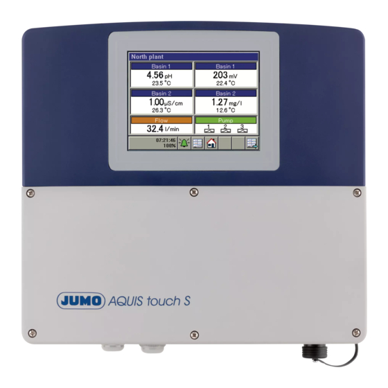
3 Device Description Device setup TFT-touchscreen Case (terminal compartment cover opened) Connection terminals, power supply unit Connection terminals, base unit Expansion slots USB interfaces (USB device interface and connection for optional USB host socket) USB host socket, IP67 (also available, see Extra Code 269 Chapter 4.2 "Order details", Page 17) Cable fittings... -
Page 15: Identifying The Device Version
4 Identifying the device version Nameplate The nameplate on the device enclosure identifies the device version. It is locat- ed on the outside of the enclosure on the right. Example of a nameplate Data matrix code (for service purposes) Information symbol (Read documentation! ⇨... - Page 16 4 Identifying the device version ⇨ "Order details", page 17 In the event of technical questions, please have the information from the name- plate available for the member of our support team.
-
Page 17: Order Details
In addition to the standard languages of German, English, and French, 13 ad- ditional languages (e.g. Russian, Chinese, Italian etc.) are available. Please use the contact information on the back of this manual to contact JUMO in this regard. Slot... - Page 18 4 Identifying the device version (8) Input/output 1 IN 11, OUT 6/7 Not used Universal input Relay (changeover contact) 2× relays (normally open contact) Solid state relay triac 230 V, 1 A Logic output 0/22 V 2× logic outputs 0/12 V analog output 2×...
- Page 19 4 Identifying the device version (12) Output 5 OUT 14/15 Not used Relay (changeover contact) 2× relays (normally open contact) Solid state relay triac 230 V, 1 A Logic output 0/22 V 2× logic outputs 0/12 V analog output 2× PhotoMOS® solid-state relay Supply voltage output ±5 V DC, 24 V (13) Output 6...
-
Page 20: Scope Of Delivery
Mini-DVD with JUMO PC setup program as demo version, Adobe Acrobat Reader, operating manual and data sheet in PDF format, GSD generator and JUMO PCC / PCA 3000 as demo version JUMO AQUIS touch S accessories kit, part no. 00597460 Mounting plate for surface mounting, part no. -
Page 21: Accessories
Panel mounting kit 00602403 Pipe-mounted kit 00602401 Protective roof kit 00602404 JUMO PC setup program AQUIS touch S/P, 00594355 (PG202599) JUMO PCA3000/PCC software package 00431884 PhotoMOS® is a registered trademark of Panasonic. The USB flash drive indicated has been tested and is designed for industrial applications. No liability is assumed for flash drives from other manufacturers. - Page 22 4 Identifying the device version...
-
Page 23: Mounting
5 Mounting Important information DANGER! Under no circumstances may the device be installed or removed while under voltage! This poses the risk of electrocution. Switch-off the entire system beforehand. This work must be performed only by qualified personnel! The device must never be installed in potentially-explosive areas! There is the risk of an explosion. -
Page 24: Dimensions
5 Mounting Dimensions View from below (cable entries) 137.5 mm 120.5 mm 270.5 mm 33.3 mm 301.5 mm Side view Front view... -
Page 25: Surface Mounting
Mounting plate for surface mounting Self-tapping screws 60 × 16 TORX PLUS® 30IP (supplied as stan- dard with the JUMO AQUIS touch S) Fastening screws (hex-headed screws Ø 6 mm) TORX PLUS® is a registered trademark of Acument Intellectual Pro-perties, LLC. - Page 26 5 Mounting JUMO AQUIS touch S Fastening screws (hex-headed screws Ø 6 mm) Weather protection canopy, stainless steel 1.4301 (part no. 00602404) Drilling diagram 6.6 mm 299 mm...
- Page 27 5 Mounting Procedure Step Action Use the drilling diagram to mark the mounting holes on the mount- ing surface. You can also use the mounting plate as a template for this purpose. Leave enough space around the cable entries to permit routing of cables.
-
Page 28: Pipe Mounting
Pipe/mast (customer provision) with a diameter of 35 to 55 mm Self-tapping screws 60 × 16 TORX PLUS® 30IP (supplied as stan- dard with the JUMO AQUIS touch S) Pipe clips from the pipe mounting kit (part no. 00602401) Mounting plate for pipe mounting from the pipe mounting kit (part no. - Page 29 5 Mounting Procedure Step Action Using the screws (2), fasten the mounting plate (4) and possibly the weather protection canopy (6) to the right side of the unit (5). Insert the two pipe clips (3) through the slots in the mounting straps on the mounting plate (4) as shown in the drawing.
-
Page 30: Panel Installation
NOTE! Installation in a control panel provides protection class IP20. When the JUMO AQUIS touch S is installed in the wall of control cabinets, the protection class of the control cabinet no longer applies; instead, the protection class for instal- lation in a control panel applies (IP20). - Page 31 (part no. 00602403) Self-tapping screws 60 × 16 TORX PLUS® 30IP (supplied as stan- dard with the JUMO AQUIS touch S) JUMO AQUIS touch S Control panel with cutout 273 mm × 257 mm Material thickness of panel: 1.5 to 5 mm TORX PLUS®...
- Page 32 5 Mounting...
-
Page 33: Electrical Connection
6 Electrical connection Installation notes DANGER! Observe the following instructions! Qualification of personnel • The electrical connection must only be carried out by qualified personnel. Electrical wiring • When selecting the electrical wiring material as well as when installing and connecting the device electrically, comply with the requirements of DIN VDE 0100 "Low-voltage electrical installations"... - Page 34 6 Electrical connection Electrical safety • Disconnect all phases of the power supplied to the device (power grid, out- side power supply sources for relays/solid state relays etc.) If current-carry- ing components could be touched while work is being performed. •...
-
Page 35: Installing And Connecting Cables
6 Electrical connection Installing and connecting cables 6.2.1 Opening the terminal compartment on the device Step Action Loosen the screws on the terminal compartment cover. Remove the terminal compartment cover. NOTE! After all work in the terminal compartment has been completed, ensure that the terminal compartment cover is reattached. -
Page 36: Installing Cables
6 Electrical connection 6.2.2 Installing cables Strain relief strip IP67 cable fittings Procedure Step Action Insert the provided cable fittings, together with the appropriate seals, into the corre- sponding cable entry openings in the enclosure and then tighten the glands with the lock nuts. - Page 37 6 Electrical connection NOTE! Open or improperly sealed cable fittings void the protection type IP67 for the en- closure. Ensure that all cable fittings are sealed and tightened to the correct in- stallation torque. ⇨ Chapter 20.14 "Case", page 121...
-
Page 38: Preparing Coaxial Cables For Ph/Redox Electrodes
6 Electrical connection 6.2.3 Preparing coaxial cables for pH/redox electrodes ® Coaxial cable with Shield-Kon connector Length Part number 1.5 m 00085154 00307298 10 m 00082649 Preparing your own coaxial cable 25 mm Sensor Remove outer sheathing from the cable > Pull back the braided shield Inner conductor Shield-Kon®... - Page 39 6 Electrical connection Inner conductor Shrink sleeve Use shrink tubing to insulate the braided shield NOTE! The black, semiconducting layer must not touch with the inside conductor! This would short-circuit the signal from the pH electrode. Preparing a shielded multiconductor cable 60 mm Strip the insulation off the connecting cable and pull back the shield 60 mm...
-
Page 40: Conductor Cross-Sections For Base Unit And Power Supply Unit
6 Electrical connection 60 mm Shield-Kon® connector Use shrink tubing to insulate the shield and Shield-Kon® connector 6.2.4 Conductor cross-sections for base unit and power supply unit The terminals on the base unit and power supply unit are spring-cage terminals. Ferrule Conductor cross sec- Length to... -
Page 41: Conductor Cross-Sections For Optional Boards
6 Electrical connection 6.2.5 Conductor cross-sections for optional boards The terminals on optional boards are plug-in screw terminals. Optional boards for Ferrule Conductor cross sec- Length to tion strip minimal Maximum Universal inputs without ferrule 0.14 mm 1.5 mm 7 mm Analog outputs with ferrule with lip 0.25 mm... -
Page 42: Galvanic Isolation
If sensors that are not electrically isolated are connected to a digital input and supplied by an external power source, potential differences between the in- ternal and external ground can cause problems. Providing the supply voltage from the voltage supply outputs of the JUMO AQUIS touch S is preferable in such cases. -
Page 43: Connection Diagram
6 Electrical connection Connection diagram 6.4.1 Overview of connections Module Connector terminal Type Inputs Base IN 1 to IN 3 Digital inputs unit IN 4 to IN 5 Temperature inputs IN 6 Universal input Option- IN 7 to IN 10 analysis inputs IN 11 to IN 12 Universal inputs... -
Page 44: Analog Inputs Base Unit
6 Electrical connection 6.4.2 Analog inputs base unit Connector/ Connection variant Symbol terminal IN 4 RTD temperature probe 2-wire circuit Pt100, Pt1000 or customer-specific characteristic line RTD temperature probe 3-wire circuit Pt100, Pt1000 or customer-specific characteristic line IN 5 RTD temperature probe 2-wire circuit Pt100, Pt1000 or customer-specific characteristic line... -
Page 45: Analog Inputs Optional Boards
6 Electrical connection 6.4.3 Analog inputs optional boards Universal inputs Slot Connection variant Symbol IN 11 RTD temperature probe IN 12 2-wire circuit Pt100, Pt1000 or customer-specific characteristic line RTD temperature probe 3-wire circuit Pt100, Pt1000 or customer-specific characteristic line Resistance potentiometer A = Start E = End... - Page 46 6 Electrical connection pH/Redox/NH3 analysis inputs There are currently 2 versions of the "pH/Redox/NH3 analysis input" optional board in use. The connection diagram contains the connection terminal layout for both version I and version II. To identify the version of your optional board, compare the connection terminal layout to the following illustrations: 4 5 6 1 2 3...
- Page 47 The conductor colors listed refer to JUMO ISFET-pH sensors. The orange-colored conductor is not con- nected. The connection diagram for the selected analog input concerned must be observed when connecting the...
- Page 48 When connecting the temperature probe of JUMO ISFET pH sensors to process connection 615 (NTC 8k55), no customer-specific linearization like that for the JUMO AQUIS 500 pH is needed. The IN 5 tem- perature input supports connection of 8k55-NTC temperature probes.
- Page 49 6 Electrical connection Slot Option/connection variant Symbol IN 7 pH/Redox IN 8 Asymmetric connection of a combination electrode with IN 9 integrated resistance thermometer and VarioPin termi- IN 10 nal head The RTD temperature probe is used to provide a tempera- ture-compensated pH-value measurement, and can be con- nected to a temperature input or universal input.
- Page 50 6 Electrical connection Slot Option/connection variant Symbol IN 7 pH/Redox IN 8 Symmetric connection of a combination electrode IN 9 Symmetric connection is used to reduce interference from IN 10 stray electromagnetic fields along the sensor cable. A = Glass/metal electrode (core) B = Reference electrode (inner shield) C = Liquid potential (grounding pin, pipe, or container wall at the measuring point)
- Page 51 6 Electrical connection Slot Option/connection variant Symbol IN 7 pH/Redox IN 8 Symmetric connection of a combination electrode with IN 9 integrated resistance thermometer and VarioPin termi- IN 10 nal head Symmetric connection is used to reduce interference from stray electromagnetic fields along the sensor cable. The RTD temperature probe is used to provide a tempera- ture-compensated pH-value measurement, and can be con- nected to a temperature input or universal input.
- Page 52 2-electrode system with 2-wire conductor Terminal 1 must be connected to the outer electrode on concentric conductivity sensors. A = Outer electrode (core color for JUMO types with fixed ca- ble: White) B = Inner electrode (core color for JUMO types with fixed ca-...
- Page 53 CR optional board (resistive conductivity measurement) 4-electrode system A = Outer electrode 1 (I hi) (core color of CR-4P cable for JUMO types: Red) B = Inner electrode 1 (U hi) (core color of CR-4P cable for JUMO types: Gray)
-
Page 54: Analog Outputs
6 Electrical connection 6.4.4 Analog outputs Base unit Connector/ Connection variant Symbol terminal OUT 4 analog output DC 0 to 10 V or DC 0(4) to 20 mA (configurable) OUT 5 analog output DC 0 to 10 V or DC 0(4) to 20 mA (configurable) Optional boards Slot... -
Page 55: Binary Inputs
6 Electrical connection 6.4.5 Binary inputs Base unit Connec- Connection variant Wire Potential Terminal Symbol tor/ 24 V IN 1 IN 2 IN 3 terminal IN 1 to 3 Digital input Potential- (potential-free contact) free contact In the digital input configuration, the "Contact" option must be set to "Potential-free contact". - Page 56 6 Electrical connection Connec- Connection variant Wire Potential Terminal Symbol tor/ 24 V IN 1 IN 2 IN 3 terminal IN 1 to 3 Digital input Switching (PNP transistor switch- signal ing output) (collector) Sensor - Sensor + Sensor - In the digital input configuration, the "Contact"...
-
Page 57: Binary Outputs, Power Supply Unit Board
6 Electrical connection Optional boards Connector/ Connection variant Symbol terminal IN 13/14/15 3× binary input IN 16/17/18 (potential-free contact) 6.4.6 Binary outputs, power supply unit board Connector/ Connection variant Symbol terminal OUT 1 Relay OUT 2 N/O contact OUT 3 Relay Changeover contact... -
Page 58: Binary Outputs, Optional Boards
6 Electrical connection 6.4.7 Binary outputs, optional boards Slot Option/connection variant Symbol OUT 6/7 Relay OUT 8/9 Changeover contact OUT 10/11 OUT 12/13 OUT 14/15 2× relay OUT 16/17 N/O contact OUT 18/19 Solid state relay triac 230 V/1 A 2×... -
Page 59: Mains Power Connection
6 Electrical connection 6.4.8 Mains power connection Connector/ Connection variant Symbol terminal PWR IN Mains power input 6.4.9 Voltage supply outputs Base unit Connector/ Connection variant Symbol terminal DC ±5 V Voltage supply (e. g. ISFET sensor or digiLine) DC 24 V Voltage supply for external transmitters... - Page 60 6 Electrical connection Power supply unit board Connector/ Connection variant Symbol terminal PWR OUT Mains voltage lead out Optional board Slot Connection variant Symbol OUT 14/15 Voltage supply DC 24 V for external transmitters 24 V Voltage supply DC ±5 V (e.
-
Page 61: Interfaces
6 Electrical connection 6.4.10 Interfaces NOTE! When installing the bus cabling for digital sensors, heed the information regard- ing line length and number of sensors in the Annex. ⇨ Chapter 21.2 "Planning the cabling for digital sensors", page 129 Base unit interfaces Connector/ Connection variant Symbol... - Page 62 COM 1 digital sensors For connection of a digiLine bus line to operate digital sen- sors, JUMO offers 5-wire M12 digiLine Master connecting cable. A total of up to 6 sensors with digiLine electronics and +5 V digital sensors from the product groups 2026xx can be oper- ated over a digiLine bus.
- Page 63 6 Electrical connection Optional board interfaces Slot Connection variant Terminating resistors Symbol COM 2 RS422 with terminating resistors RxD+ terminating resistors with RxD- DIP switches on TxD+ optional board configurable without terminating resistors TxD- RS485 RxD/TxD+ terminating resistors with RxD/TxD- DIP switches on optional board configurable...
- Page 64 Connection to optional board: RS422/485 serial interface without terminating resistors +5 V For connection of a digiLine bus line, JUMO offers 5-wire M12 digiLine Master connecting cable. Up to 6 sen- sors with digiLine electronics can be operated over a dig- +24 V iLine bus.
- Page 65 6 Electrical connection Slot Connection variant Terminating resistors Symbol COM 2 PROFIBUS-DP — 3 = RxD/TxD-P 5 = DGND 6 = VP 8 = RxD/TxD-N Ethernet — Type RJ 45 (socket) NOTE! Only 1 serial interface per device can be used for digiLine (see Chapter 10.13 "Serial interfaces", page 44).
- Page 66 6 Electrical connection...
-
Page 67: Startup
When the battery is empty a battery alarm will indicate that status. The battery must be exchanged before it is empty. The bat- tery must be exchanged by the JUMO Service department! In this case, send in the device! -
Page 68: Basic Setup
7 Startup Basic setup This chapter deals with the most important settings for initial startup of the de- vice. The installation instructions discuss the settings for: • Analog and digital inputs • Display and visualization of the input signals on overview screens and indi- vidual screens •... -
Page 69: Basic Settings
7 Startup Parameters Selection/ Explanation setting option • Day in month first Number of the selected second weekday for switch to standard third time in the respective month fourth last • Time hh:mm:ss Time to switch to standard time 7.2.2 Basic settings The "Basic Settings"... -
Page 70: Digital Sensors
The baud rates of the digiLine electronics and the serial interface of the JUMO AQUIS touch P must match. A bus scan can be used to change a pos- sibly incorrect baud rate for the connected digiLine electronics to the correct setting (see Chapter 8.2.7 "Digital sensors", page 97). - Page 71 Chapter "Procedure for manual linking of sensors", page 100 Configuring the inputs for digital sensors: ⇨ Chapter 10.10 "Digital sensors", page 29 The following table describes the startup procedure for an individual JUMO sen- sor with digiLine electronics. Step Action Log in as user "Master"...
- Page 72 JUMO sensors with a digital interface from the product groups 2026xx can com- municate with the JUMO AQUIS touch S over the digiLine bus just like JUMO sensors with digiLine electronics. However, they do not support plug & play and must be put into operation in another way.
- Page 73 7 Startup Step Action Check whether this entry has the status "Installation". If this is not the case, check the configuration of the selected input for digital sensors. Example of view showing the status of assignment table entries: linked Installation ⇨...
-
Page 74: Restarting And Replacing
When replacing JUMO digiLine electronics assemblies, each electronics as- sembly must be replaced individually before the next one is disconnected from the bus. -
Page 75: Function Test
⇨ Chapter 9.1 "Installing optional boards", page 111 If this is not successful, contact Technical Support at JUMO. The contact data can be found on the back of these installation instructions. 7.4.2 Checking sensors and inputs/outputs To check correct operation of all inputs/outputs, you can display the current an- alog and binary values. - Page 76 7 Startup • Uncompensated: Value measured by sensor (raw value of the measure- ment input, e.g. pH measuring chain voltage) These sensor values are subject to distortion caused by outside factors. Display of uncompensated values is used primarily for diagnostic purposes. The compensated values are used for the actual measurement of analysis variables.
-
Page 77: Operation
The passwords in the device can be changed. ⇨ Chapter 8.2.1 "Logon/Logoff", page 91 The JUMO PC setup program is needed to change user names and user rights. ⇨ Refer to B 202581.0 for user management The following table provides an overview of the factory-set user accounts. - Page 78 8 Operation Factory-set user rights Users Every- User 2 User 1 Service Master User rights Display of: • Current measuring values on overview and detailed screens • Configuration data • parameters • Device information Display of: • History of measurement data in the recording function •...
-
Page 79: Display And Control Elements
8 Operation 8.1.2 Display and control elements (4)(5) (7) (8) Touchscreen Toolbar with buttons for operation "Device menu" button with display of: • Date and time • Logged-in user ("Master" in the example) • Remaining memory display in percent for recording function (in the example: 100 %) "Alarm/Event List"... -
Page 80: Menu Structure
8 Operation 8.1.3 Menu structure At the operating level, 3 different navigation buttons are available to select ap- propriate screens for display and control of device functions. The "Device menu" and "Alarm/event list" menu levels are also displayed by means of corresponding buttons. The device menu contains submenus for set- ting, servicing, and diagnosing the device and its functions. - Page 81 8 Operation Overview of the menu structure Operating level Home Select Next operator operator display display Navigation in the operating loop Plug-in USB flash drive Device settings Memory Alarm-/ menue manager event list Secure hardware Login/logoff Alarm list remove Recorder Event list Calibration Update to USB...
- Page 82 8 Operation NOTE! The "Recorder Update to USB" and "Recorder Backup to USB" items appear in the "Memory Manager" menu only if the extra "Recording function" is en- abled. ⇨ Chapter 4.2 "Order details", page 17...
- Page 83 8 Operation Operation screens in the operation loop (16) (15) (14) (13) (12) (11) (10) Diagram Operator screen Description General screen 1 Freely configurable overview display of measuring values and dig- ital signal states General screen 2 The overviews can be configured as a 2-part screen or a 4-part screen.
- Page 84 8 Operation Diagram Operator screen Description Detailed screen 1 Freely configurable large-section screen Detailed screen 2 Display of 1 main measuring value, 1 second measuring value, 1 Detailed screen 3 additional value and up to 3 binary values, as well as additional vi- Detailed screen 4 sualization of the main measuring value and the alarm limits for an Detailed screen 5...
- Page 85 The result from a formula is invalid (e.g. division by zero) The extra code "Math and logic module" is explained in the JUMO AQUIS touch S operating manual. ⇨ B 202581.0 Display overrun: The value to be displayed is outside the limits of -99999 to 99999.
-
Page 86: Entry Of Text And Numbers
8 Operation 8.1.4 Entry of text and numbers Dialogs for entry of text or numbers appear automatically when the correspond- ing entry field is tapped. Text entry dialog There are 2 special features in addition to conventional entry of characters: •... - Page 87 8 Operation Number entry dialog This dialog opens if an entry field for numerical values is tapped. Special feature : The "Exp" button permits entry of an exponent as a power of ten. Procedure: Enter the numerical base value > Tap "Exp" > Enter the exponent > Confirm the entry Entry dialog buttons Explanation...
-
Page 88: Device Menu
8 Operation Device menu NOTE! Operation depends on the user's rights. Operating and setting options are re- stricted, depending on the user who is logged in. The "Master" and "Service" users have access to all menus and functions (fac- tory setting). ⇨... - Page 89 No user level is configured at the factory. The user level must be configured and loaded into the device with the aid of the JUMO PC setup program. The "User Level" entry does not appear in the device menu as long as no user level is config- ured.
- Page 90 8 Operation To navigate in submenus, menu items are opened by tapping the folder icons identified with a plus sign. Open menu structures are identified with a minus sign and can be closed again by tapping the folder icon. Currently open windows can be left either by tapping "Exit" or the "Close win- dow"...
-
Page 91: Logon/Logoff
The logon/logoff dialog is open • The memory manager is open • During calibration of analysis sensors • During calibration of the touchscreen The re-authentication time is set using the JUMO PC setup program. ⇨ Chapter 21.8.3 "User list", page 306... -
Page 92: User Level
8.2.2 User level The user level consists of a user-defined list of parameters and configuration settings. You need the JUMO PC setup program to configure the user level. ⇨ see B 202581.0 in the "PC Setup Program" chapter The user level can be opened from the device menu only if it has been config- ured beforehand with the aid of the PC setup program. -
Page 93: Functional Level
8 Operation 8.2.3 Functional level The functional level is used primarily for testing and diagnostic purposes. Analog and binary values of the outputs can be controlled manually here. This may be useful, for instance, for checking an individual piece of equipment in a plant. When performing maintenance and repair work, counters for operating hours, switching actions and flow rates can be reset. - Page 94 8 Operation Manual control of analog/digital outputs Activate the configuration setting "Enable menu mode" for the outputs you wish to control manually. "Manual mode buttons" buttons for manual control for these outputs then appear at the functional level. To adjust output values manually, proceed as follows: Select Device Menu >...
-
Page 95: Device Information
8 Operation 8.2.4 Device information For testing and diagnostic purposes, the "Device info" menu provides access to extensive data about the hardware and software of the device, as well as current analog and binary values. Device Info menu items: • General: Information about the main board, device software and Ethernet configuration •... -
Page 96: Service
Chapter 9.3 "Ci base calibration", page 121 • Digital sensor 1 to 6: For each digital JUMO sensor from the product group 2026xx that is operating on the device, a menu appears here that allows you to reset the calibration date of the sensor to the default settings. -
Page 97: Calibrating The Touchscreen
When the battery is empty a battery alarm will indicate that status. The battery must be exchanged before it is empty. The bat- tery must be exchanged by the JUMO Service department! In this case, send in the device! 8.2.6... - Page 98 Explanation Symbol linked Communication between the sensor electronics and the JUMO AQUIS touch S has been suc- cessfully established. The sensor is operating. Installation The device searches for the individual assign- ment table entry of a linkable sensor. A new sen-...
- Page 99 With the "Link" button, you can access the submenu for linking sensors that are not linked. Digital sensors from the JUMO prod- uct groups 2026xx must be linked by means of this button during startup.
- Page 100 In the list of detected sensors, highlight the one that you wish to link with the previously highlighted assignment table entry. JUMO sen- sors with digiLine electronics can be identified by the hardware ad- dress on the nameplate of the digiLine electronics. It is also displayed in the list of detected sensors and in the sensor informa- tion ("Info"...
- Page 101 8 Operation Bus status display The operating status of the digiLine bus is visualized in the title bar. The symbols used for this and their meaning are explained in the following table. Green There are no bus errors. All sensors are linked and functioning. This symbol appears in the title bar when connecting sensor electronics that have not yet been linked with the device.
-
Page 102: Alarm/Event List
8 Operation Alarm/Event list The JUMO AQUIS touch S offers the option of configuring alarm functions and event functions in numerous functions. In addition, the electronics of the JUMO AQUIS touch S are self-monitoring and trigger corresponding preprogrammed alarms and events in case the internal device malfunctions. -
Page 103: Alarm List
8 Operation 8.3.1 Alarm list The alarm list displays the current alarms. Alarms are cleared upon elimination of the alarm condition. Each alarm triggers a "collective alarm". The alarm list view contains buttons for viewing details about alarms and acknowledging col- lective and dosing alarms. - Page 104 8 Operation All alarms are available in the binary selector. In this way, digital outputs or other internal functions of the device can be controlled via alarms.
- Page 105 8 Operation Acknowledging collective/dosing alarms The collective alarm combines all alarms in the alarm list. It simplifies signaling of one or several active alarms with external indicating devices or to control rooms. The digital signal for the collective alarm is available in the binary selec- tor in 2 versions: •...
-
Page 106: Event List
8 Operation 8.3.2 Event list A number of situations that are essential for tracking and diagnostic purposes are logged in the event list. The entries are identified with corresponding icons on the basis of the type of event. In addition, events are logged with an icon in the data monitor/recording function. - Page 107 8 Operation The following table provides an overview of the possible entries in the event list. Events Symbol Power on Power off Alarm occurred Alarm cleared • Configured event (condition occurred) • Calibration start • Timer start • Wash contact start •...
-
Page 108: Memory Manager (Usb Flash Drive)
The measurement data are stored in DAT files and the configuration data in SET files. These files can be opened and evaluated with the aid of the JUMO PCA3000 evaluation software. Data that has been read out is marked inter- nally as retrieved and the available memory display is reset to 100 %. - Page 109 The measurement data are stored in DAT files and the configuration data in SET files. These files can be opened and evaluated with the aid of the JUMO PCA3000 evaluation software.
- Page 110 Software Update: The device software can be updated with the aid of a USB flash drive. To do so, an appropriate update file must have been saved the flash drive in advance; this file can be obtained from JUMO Service. CAUTION! It is strongly recommended that the configuration and recorder data be backed prior to performing a software update.
-
Page 111: Retrofitting Optional Boards
9 Retrofitting optional boards Installing optional boards DANGER! Installation and removal of optional boards must be performed only by qualified personnel. To ensure electrical safety, country-specific regulations must be ob- served. The following step-by-step table explains in detail the procedure for retrofitting optional boards: Step Action... - Page 112 9 Retrofitting optional boards Step Action Unscrew the 2 screws in the cover plate over the selected optional board slot and remove the cover plate. Insert the optional board in the selected slot. Ensure that the board is seated correctly. For better guidance of the board, you can fill empty slots with plastic board frames.
- Page 113 9 Retrofitting optional boards Step Action Install the M12 socket supplied with the optional board in a suitable cable entry opening in the case. Connect the 2-wire temperature sensor cable from the socket to an appropriate analog input (e. g. temperature measurement input). Observe the information regarding the integrated temperature sen- sor in the conductivity sensor.
-
Page 114: Energy Balance Test
"red" RPM range. Nevertheless, this is possible for a brief period of time. Increased wear, however, must be expected. A demo version of the JUMO PC setup program is provided on the CD included with the JUMO AQUIS touch S. Alternatively, you can also download the soft- ware from the JUMO home page free of charge. -
Page 115: Monitoring The Internal Temperature
USB host interface • LAN interface (Ethernet) NOTE! If Microsoft® Windows® is already running, all Windows programs must be closed before installing the JUMO PC setup program. 1.Microsoft, Windows XP, Windows Vista and Windows 7 are registered trademarks of Microsoft Corporation. - Page 116 9 Retrofitting optional boards Procedure Step Action With the PC running, insert the CD into the drive and close it. After the CD has been inserted, the installation program starts automatically; if this does not happen, proceed as follows: Start the "Launch.exe" file in the main directory of the CD. The installation program proceeds through the rest of installation accompanied by on- screen messages.
- Page 117 Click the "Install" button and wait until the installation has completed. NOTE! If the "30-day test version" option is set during installation, the JUMO PC setup program is fully function for 30 days. After 30 days, the program switches au- tomatically to a "demo version"...
-
Page 118: Performing The Energy Balance Test
Action Launch the JUMO PC setup program from the Windows® Start menu If you are using the demo version of the JUMO PC setup program, enter "Demo" as user ID and confirm by pressing "OK". Open the "Device Version" menu item by double-clicking on it. - Page 119 9 Retrofitting optional boards Step Action In the "Configuration of Optional Plug-in Cards" window, set the ambient tempera- ture acc. to the prevailing conditions at the planned installation site. For temperatures up to 40 °C or 104 °F, select "40 °C / 104 °F". For temperatures in the range of 40 to 50 °C or 104 to 122 °F, select "50 °C / 122 °F".
- Page 120 9 Retrofitting optional boards Step Action Installation of the planned complement of optional boards poses no concerns if the energy balance limit has not been exceeded. Microsoft and Windows 7 are registered trademarks of Microsoft Corporation.
-
Page 121: Ci Base Calibration
When the battery is empty a battery alarm will indicate that status. The battery must be exchanged before it is empty. The bat- tery must be exchanged by the JUMO Service department! In this case, send in the device! - Page 122 ⇨ Chapter 8.1.1 "Passwords and user rights", page 77 Ensure that the electronics of the JUMO AQUIS touch S have reached operating temperature. You can view the board tempera- ture at: Device Menu > Service > Service Data > "Internal Data" tab Ensure that the ambient temperature specified for the device cor- responds to the conditions for the normal operating mode.
- Page 123 9 Retrofitting optional boards Step Action Place the wire of the calibration sensor with 2 windings through the opening in the Ci sensor without connecting the ends of the wires. Start the Ci base calibration Device Menu > Service > Ci-base Calibration IN 7 to 10 Enter the cell constant for the sensor and confirm by pressing "OK".
- Page 124 9 Retrofitting optional boards Step Action Connect the ends of the wires forming the conductor loop of the calibration adapter. Set the calibration adapter to the resistance value shown in the in- struction text in the display (in the example: 20 kΩ). Once the mea- sured value displayed has stabilized, confirm by pressing "OK".
- Page 125 9 Retrofitting optional boards Step Action Once all measurings have been confirmed, a summary of the cali- bration data acquired appears. Confirm by pressing "OK". If the Ci base calibration fails, the procedure is canceled without acceptance of the calibration data. Protocol after successful Ci base calibration...
- Page 126 9 Retrofitting optional boards...
- Page 130 JUMO GmbH & Co. KG JUMO Instrument Co. Ltd. JUMO Process Control, Inc. Street address: JUMO House 6733 Myers Road Moritz-Juchheim-Straße 1 Temple Bank, Riverway East Syracuse, NY 13057, USA 36039 Fulda, Germany Harlow, Essex CM 20 2DY, UK Phone:...
Need help?
Do you have a question about the AQUIS touch S 202581 and is the answer not in the manual?
Questions and answers