Table of Contents
Advertisement
Quick Links
Advertisement
Table of Contents

Related Manuals for GRAPHTEC GL500


Summary of Contents for GRAPHTEC GL500
- Page 1 GL500 USER’S MANUAL MANUAL NO. GL500-UM-151...
-
Page 2: Introduction
User's Manual. Moreover, use of the GL500 by incorrect procedures may result in damage to the GL500 or may invalidate its safeguards. Please confirm all of its notes regarding use and other related information to ensure correct use. - Page 3 (7) Insofar as possible, position the GL500 input signal cables away from any other cables which are likely to be affected by electromagnetic interference. (8) For stabilized measurement, allow the GL500 to warm up for at least 30 minutes after turning it on.
-
Page 4: To Ensure Safe And Correct Use
Conventions Used in This Manual To promote safe and accurate use of the GL500 as well as to prevent human injury and property damage, safety precautions provided in this manual are ranked into the five categories described below. Be sure you understand the difference between each of the categories. -
Page 5: Safety Precautions
50 V (DC or rms). If the GL500 generates smoke, is too hot, emits a strange odor , or otherwise functions abnormally, turn off its power and unplug its power cable from the electrical socket. - Page 6 Safety Precautions Safety Precautions WARNING Avoid using the GL500 in places where it may be exposed to water such as bathrooms, locations exposed to wind and rain, and so on. Avoid water Watch out for electrical shock Prevent dust or metallic matter from adhering to the power supply connector.
- Page 7 Safety Precautions Safety Precautions CAUTION Do not use or store the GL500 in a location exposed to direct sunlight or the direct draft of an air conditioner or heater. • Such location may impair the GL500's performance. Storage/Use prohibited Do not place coffee cups or other receptacles containing fluid on the GL500.
- Page 8 • Such action may cause the GL500 to break down. No lubrication Never clean the GL500 using a volatile solvent (such as thinner or benzene). • Such action may impair the GL500's performance. • Clean off any soiled areas using a soft dry cloth.
-
Page 9: Table Of Contents
2 Checks and Preparation Checking the Outer Casing......................2-2 Checking the Accessories ......................2-2 GL500 Part Names and Functions ....................2-3 Monitor Part Names and Functions ..................... 2-4 Control Panel Key Names and Functions ..................2-6 Connecting to a PC ........................2-7 Connection Using a LAN Cable .................... - Page 10 9. CURSOR key ........................3-6 Setting Procedures ........................3-7 1. Inputting Signals ........................3-7 2. Setting up the GL500 ......................3-7 3. Capturing Data to Memory ....................3-8 4. Replaying Current Data ......................3-8 5. Replaying Event Data ......................3-9 6.
- Page 11 Other ............................4-33 Information ..........................4-34 4.10 View Functions .......................... 4-35 Data Capture Start/Stop ......................4-35 GL400/350 ..........................4-36 GL500 + GL400/350 ........................ 4-38 Y-T ............................4-39 Digital View ..........................4-40 X-Y ............................4-41 FFT ............................4-41 Calculation ..........................4-42 4.11 Review Device ...........................
- Page 12 Contents Function Specifications ........................ 5-7 Function Types .......................... 5-7 Trigger Functions (Current) ....................... 5-7 Trigger Functions (Event) ......................5-7 External Input/Output Functions ....................5-8 Accessory/Option Specifications ....................5-9 Control Software ........................5-9 Battery Pack (Option) ........................ 5-9 External Dimensions ........................5-10 Index ................................
-
Page 13: General Description
CHAPTER General Description This chapter provides a general description of the GL500 and its features. Overview Features Operating Environment Notes on Temperature Measurement Notes on Using the Monitor Changing the Display Language... -
Page 14: Overview
General Description 1.1 Overview The GL500 is capable of faithful measurement of sudden events, both low- and high-speed, while simultaneously performing data capture or long-term measurement. It is a compact, lightweight data logger that comes equipped with a large color display monitor and built-in memory, and can be connected to a PC... -
Page 15: Features
An alarm output function is also provided. Note: Please consult your sales representative or nearest Graphtec vendor for more information on combining and increasing the number of input terminal units. - Page 16 Moreover, since the application software screens are similar in appearance LOCAL to those of the GL500 screens, they can be used intuitively, in the same manner. ENTER Waveform and digital data screens can be displayed at the same time.
-
Page 17: Operating Environment
CHECKPOINT If condensation occurs... Condensation occurs in the form of water droplets on the device surfaces and interior when the GL500 is moved from a cold to a warm location. Using the GL500 with condensation present will cause malfunctioning. Wait until the condensation has disappeared before turning on the power. -
Page 18: Notes On Temperature Measurement
Please observe the following precautions when performing temperature measurement. (1) Do not block the air vents. Always provide a space of at least 30 cm on all sides of the GL500. (2) For stabilized temperature measurement, allow the GL500 to warm up for at least 30 minutes after turning it on. -
Page 19: Checks And Preparation
CHAPTER Checks and Preparation This chapter explains how to check the GL500's external casing and accessories, and how to prepare the GL500 for operation. Checking the Outer Casing Checking the Accessories GL500 Part Names and Functions Monitor Part Names and Functions... -
Page 20: Checking The Outer Casing
Checks and Preparation 2.1 Checking the Outer Casing After unpacking, check the GL500's outer casing before use. In particular, please check for the following: • Surface scratches • Other flaws such as stains or dirt 2.2 Checking the Accessories After unpacking, check that the following standard accessories are included. The accessories included will differ depending on the model purchased. -
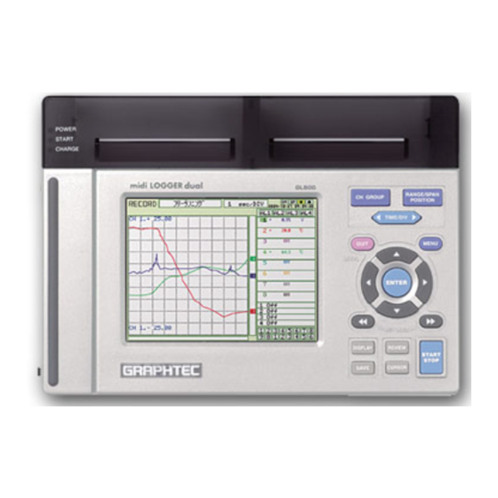
Page 21: Gl500 Part Names And Functions
Checks and Preparation 2.3 GL500 Part Names and Functions This section describes the names and functions of parts of the GL500. (4) Monitor (5) Control panel keys (2) Data capture LED (3) Battery charging (1) Power LED Top panel (11) External trigger terminal... -
Page 22: Monitor Part Names And Functions
......The red LED flashes while data on the PCMCIA card is being accessed. (5) Key lock ....... Lit when the GL500 is in key lock status. To enable key lock status, hold down the two [ ] and [ ] keys for at least three seconds. - Page 23 Checks and Preparation (15) Waveform/settings window display area ......Displays the measurement signal waveforms. The menu windows are also displayed when the condition setting keys are pressed. (16) Event data display ..... Displays the event data capture status. (17) Scale upper/lower limit ..Displays the measurement scale for the range set. (18) Memory/PCMCIA display area ......
-
Page 24: Control Panel Key Names And Functions
Checks and Preparation 2.5 Control Panel Key Names and Functions This section describes the control panel keys. (2) RANGE/SPAN/POSITION key (1) CH GROUP key RANGE SPAN CH GROUP POSITION (3) TIME/DIV key TIME (4) QUIT key (5) MENU key QUIT MENU LOCAL (7) Direction keys... -
Page 25: Connecting To A Pc
Checks and Preparation 2.6 Connecting to a PC The GL500 can be connected to a PC via a LAN cable or a USB cable. Connection Using a LAN Cable Use the LAN cable to connect the GL500 to a PC. -
Page 26: Connecting The Power Cable And Turning On The Power
Grounding cable (4) Plug the AC cable into the mains power outlet. (5) Press the power switch on the GL500 to the ON side to turn on the power. CAUTION Always connect the GND terminal and refer to the safety precautions. The GL500 must be grounded... -
Page 27: Connecting To A Dc Power Supply
(3) Connect the DC output side to the power connector on the GL500. B-514 (8.5 to 24 VDC power supply) Shielded lead (– side) White (+ side) Press the power switch on the GL500 to the ON side to turn on the power. -
Page 28: Using The Battery Pack (Option)
(1) Use a screwdriver to remove the battery pack cover from the bottom panel. (2) Mount the battery pack in the direction shown by the arrow. Battery pack (3) Reattach the cover, and fasten the screw in place. CAUTION Do not use the GL500 without the cover fastened in place. 2-10... -
Page 29: Charging The Battery
When using the GL500 for charging: Approx. 4 hours (when the power supply is OFF) Using the GL500 for Charging The battery pack is charged by mounting it in the GL500, and supplying it with AC power. The battery cannot be charged, however, if the internal temperature has risen during continuous operation. -
Page 30: Inserting And Removing A Pcmcia Card
Checks and Preparation 2.9 Inserting and Removing a PCMCIA Card This section describes how to insert and remove a PCMCIA card. CAUTION • Adequate precautions against static electricity must be taken when handling PCMCIA cards. • Do not remove the PCMCIA card if the PCMCIA card access display on the monitor is flashing red. Data loss or malfunctions may occur. -
Page 31: Mounting And Removing The Input Terminal Unit
(1) Remove the cover from the input terminal mounting area. (2) As shown in the figure below, insert the input terminal unit in the GL500. At this time, be sure to check that the input terminal unit is locked onto the connector. -
Page 32: Connecting The Signal Input Cables To The Input Terminal Unit
This is a 4-channel isolated voltage input terminal unit. CHECKPOINT This input terminal unit is for use with the GL500 model only. Do not mount input terminal units for other models such as the GL400 in the GL500. Terminal Configuration and Input Signal Types 100Vp –... -
Page 33: 4Mf Input Terminal Unit
This is a 4-channel isolated voltage and temperature input terminal unit. CHECKPOINT This input terminal unit is for use with the GL500 model only. Do not mount input terminal units for other models such as the GL400 in the GL500. -
Page 34: 8Ms Input Terminal Unit
This is an 8-channel non-isolated voltage and temperature input terminal unit. CHECKPOINT This input terminal unit is for use with the GL500 model only. Do not mount input terminal units for other models such as the GL400 in the GL500. -
Page 35: Noise Countermeasures
Connect the signal chassis GND and the measuring device chassis ground. Use a short, thick lead to connect the chassis GND of the measuring device to the GL500's chassis GND. It will be even more effective if the ground potentials are the same. -
Page 36: Logic Or Pulse Input/Alarm Output Functions
Checks and Preparation 2.13 Logic or Pulse Input/Alarm Output Functions Connect the round connector of the logic/alarm cable (B-513, option) to the logic or pulse input/alarm output terminal on the GL500. Logic/alarm cable (B-513: 2-m length) Logic Input or Pulse Input Functions... -
Page 37: External Trigger Functions
Checks and Preparation 2.14 External Trigger Functions External Trigger Functions Item Description Number of channels Input voltage range 0 to +24V max. (single-ended ground input) Threshold level +2.5V Hysteresis Approx. 1 V (+2 to +3 V) TRIG 2-19... -
Page 38: Setting The Date And Time
Checks and Preparation 2.15 Setting the Date and Time If you are using the GL500 for the first time, charge the internal rechargeable battery and then make the date and time settings. CAUTION If the GL500 was not used for a period of approximately three months, the internal rechargeable battery may be discharged and the date and time reverted to the initial settings. -
Page 39: Settings And Measurement
CHAPTER Settings and Measurement This chapter describes the setting and measurement procedures for the GL500. Basic Settings and Measurement Setting Procedures Detailed Settings and Measurement Data Replay... -
Page 40: Basic Settings And Measurement
Settings and Measurement 3.1 Basic Settings and Measurement Control panel keys are provided for easy measurement. RANGE SPAN (1) CH GROUP key (2) RANGE/SPAN/POSITION key CH GROUP POSITION (3) TIME/DIV key TIME QUIT MENU LOCAL (5) Direction keys ENTER (7) REVIEW key (6) DISPLAY key DISPLAY REVIEW... -
Page 41: Range/Span/Position Key
Settings and Measurement 2. RANGE/SPAN/POSITION key These settings can be made or changed for each channel individually, even while the GL500 is running or performing measurement. CHECKPOINT The monitor is used for monitoring the measurement status only, and its settings cannot be changed. In addition, the RANGE setting can only be changed if data has not been captured. -
Page 42: Time/Div Key
Settings and Measurement SPAN settings 100 mV setting 1.00 to 200.00 mV/F.S. 10 V setting 0.100 to 20.000 V/F.S. 500 mV setting 5.0 to 1000.0 mV/F.S. 50 V setting 0.50 to 100.00 V/F.S. 1 V setting 0.0100 to 2.0000 V/F.S. 100 V setting 1.000 to 200.00 V/F.S. -
Page 43: Direction Keys
Settings and Measurement 5. Direction keys Direction keys ( ) : These keys move the cursor on the screen in the direction indicated. Direction keys ( Press these keys to scroll through captured data, move the cursor, and to select text and values on menu screens. Direction keys ( ) : Press these keys to scroll through captured data, move the cursor, enable/ disable key lock status, and to move the position when making text settings. -
Page 44: Save Key
Settings and Measurement 8. SAVE key Press the SAVE key to save data (memory data capture) and to make a copy of the screen. Save Data Save: BMP Copy: [QUIT] Exit Data Save: Current data and Event data are saved to the PCMCIA card. BMP Copy: The display screen can be saved in bitmap format. -
Page 45: Setting Procedures
3.2 Setting Procedures The following procedures explain how to perform general measurement using the MENU screens displayed on the GL500 monitor. The setting values used for the explanations are the factory default settings. 1. Inputting Signals (1) Connect the signal input cables to the input terminal unit(s). For details on the connection procedure, see Section 2.11, "Connecting the Signal Input Cables to the Input Terminal Unit". -
Page 46: Capturing Data To Memory
Settings and Measurement 3. Capturing Data to Memory (1) Press the START/STOP key to start data capture. "Memory Recording" is displayed in the simplified message display area at the top of the monitor screen. Event data capture status Simplified message display area Event data memory capture block status Amount of current data... -
Page 47: Replaying Event Data
Settings and Measurement 5. Replaying Event Data (1) Press the REVIEW key to display the Data Replay menu, use the [ ] direction keys to select "Event" for "Data Type", and then press the ENTER key to confirm your setting. Data Type: Event Data Replay Data Type: Event... -
Page 48: Detailed Settings And Measurement
Settings and Measurement 3.3 Detailed Settings and Measurement The QUIT and MENU keys enable detailed settings to be made. RANGE SPAN CH GROUP POSITION TIME (1) QUIT key (2) MENU key QUIT MENU LOCAL ENTER DISPLAY REVIEW START STOP SAVE CURSOR 1. -
Page 49: Menu Key
Settings and Measurement 2. MENU key Press the MENU key to switch through the AMP, CRNT, EVNT, CALC, FILE, I/F, OTHR and INFO setting menus. The [ ] direction keys can also be used to switch through the setting menus. CRNT EVNT CALC... - Page 50 Settings and Measurement CHECKPOINT When the CH setting is ALL, the Input, Range and Filter settings are the same for all the channels in that group. No. of CH ......Selects the number of channels for measurement. CHECKPOINT The CRNT and EVNT sampling intervals will differ according to the number of channels selected.
- Page 51 [ENTER] Apply CHECKPOINT The Scaling operation is calculated using a ratio of the Meas. Value or EU Value settings. If a ratio value that the GL500 cannot process is specified, the message above appears. (a) Meas. Value Specifies the numeric value to be converted. Set two points, the Upper and Lower parameters.
- Page 52 OK : Select to save the input text. CAUTION If [ * * ] displayed on the screen, this indicates that text from the application software has been input in a format that cannot be displayed on the GL500 monitor. 3-14...
- Page 53 Settings and Measurement (b) Line Color Use the Color Settings window to change the display colors for each channel. Other Misc. settings For voltage settings, zero point adjustment can be performed automatically, and the zero point reset. (c) Perform Auto Zero ADJ Sets the current input voltage as the zero point voltage value.
- Page 54 Settings and Measurement • EU (Engineering Unit Settings): This menu is used to scale the measured values and convert them to other units. Meas. Value: Specifies the numeric value to be converted. EU Value: Specifies output after conversion. Unit: Specifies the converted unit. The unit can be specified as a user-defined character string consisting of alphanumerics.
- Page 55 Settings and Measurement w w w w w CRNT Settings This menu is used to set the conditions for low-speed data capture. CRNT (CURRENT) Menu Structure Setting Selections available Setting method Sampling Interval 1, 2, 5, 10, 20, 50, 100, 200, 500 ms 1, 2, 5, 10, 20, 30 s ENTER→Select→ENTER 1, 2, 5, 10, 20, 30 min 1h Capture Ddestination Memory, PC card...
- Page 56 Date: Measurement starts at the specified time. Note: Since measurement starts at the specified time, make sure that the GL500 time settings are correct. Moreover, if Repeat has been set to On, data capture will start at the specified time each day.
- Page 57 Measurement is stopped at the specified time. Note: Since measurement stops at the specified time, make sure that the GL500 time settings are correct. Moreover, if Repeat has been set to On, data capture will stop at the specified time each day.
- Page 58 Settings and Measurement The trigger is activated when the signal input falls to (or goes below) the specified trigger level. Measurement starts CH.1 Win In: Specifies the lower and upper limits of the trigger level for each channel. When the signal input goes within (or is within) both limits, the trigger condition is met.
-
Page 59: Amp Settings
Settings and Measurement Amp Settings (Level Trigger) ........Specifies the alarm output conditions. Off: The alarm function is disabled. H: An alarm is generated when the signal input rises to (or exceeds) the specified alarm level. L: An alarm is generated when the signal input falls to (or goes below) the specified alarm level. -
Page 60: Evnt Settings
Settings and Measurement e e e e e EVNT Settings This menu is used to set the conditions for high-speed data capture. EVNT (EVENT) Menu Structure Setting Selections available Setting method Event Function Off, On ENTER→Select→ENTER Sampling Interval 2, 4, 5, 8, 10, 20, 50, 100, 200, 500 µs ENTER→Select→ENTER 1, 2, 5, 10, 20, 50, 100, 200, 500 ms 1 s No. - Page 61 Settings and Measurement No. of block divisions ........Specifies the number of memory blocks. (1 to 16 blocks) If the number of memory blocks is small, the amount of data that can be captured is correspondingly large. CHECKPOINT If both the Sampling Interval and No. of block divisions settings are made, the "Max capture time/block"...
- Page 62 Settings and Measurement Stop Settings Source ........ Specifies the stop condition for the capture of event data. Off: The START/STOP key is used to stop data capture. Amp: The stopping of data capture is triggered when the condition specified for CH, Logic, or Pulse is satisfied. Ext.: The stopping of data capture is triggered when a signal is input from an external trigger terminal.
-
Page 63: Calc Settings
Settings and Measurement r r r r r CALC Settings CALC Menu Structure Setting Selections available Setting method Statistical Function Average, Max, Min, P-P, RMS ENTER→Select→ENTER Channel specification ENTER→Select→ENTER Arithmetic Off, On ENTER→Select→ENTER Channel specification ENTER→Select→ENTER +, –, *, / ENTER→Select→ENTER Channel specification ENTER→Select→ENTER... -
Page 64: File Settings
Settings and Measurement t t t t t FILE Settings This menu is used to save or load the PCMCIA card settings, manage files, or return settings to their factory defaults FILE Menu Structure Setting Selections available Setting method Auto Data Save Off, On ENTER→Select→ENTER Data Save Path... - Page 65 • The file save destinations for current and event data will the locations specified as the data save destinations in the FILE menu. CAUTION Do not remove the PCMCIA card from the GL500 during a file operation. The GL500 may malfunction if the card is removed at this time. 3-27...
-
Page 66: I/F Settings
Subnet Mask: Sets the subnet mask. Port Number: Sets the port number. CHECKPOINT Be sure to restart the GL500 after settings have been made or changed. If the GL500 is used as is, the computer connections may not be performed correctly. 3-28... -
Page 67: Othr Settings
On: When the START/STOP key is pressed, a message asking you to confirm the Start/Stop operation is displayed. Screen Saver ...... Turns off the display if the GL500 is not operated within the specified interval, thus prolonging the product life of the display. - Page 68 Date/Time ......This parameter sets the date and time. When this setting is selected, a submenu appears for setting the date and time. Language ......This parameter sets the GL500's display language. Japanese: The display is in Japanese. English US: The display is in English.
-
Page 69: Info Display
Settings and Measurement i i i i i INFO Display The GL500's system settings are displayed here. Use this window to check the version and other information. 3-31... -
Page 70: Data Replay
Settings and Measurement 3.4 Data Replay Data captured at the GL500 can be replayed on the monitor, and waveform search, statistical calculation, and data save functions performed. RANGE SPAN CH GROUP POSITION (5) Switches between TIME and DIV TIME (4) Selects the Readout function... -
Page 71: Data Replay
Settings and Measurement Data Replay Press the REVIEW key and select the data to be displayed. Data Replay Data Type: Current (Memory) Screen Type: 1-screen View Execute [ENTER] Select/[QUIT] Exit Setting Selections available Setting method Data Type Current (Memory), PC Card File, Event ENTER→Select→ENTER Screen Type 1-screen View, 2-screen View... -
Page 72: Readout Menu
Settings and Measurement Readout Menu Press the Menu key after the data has been replayed to display the Readout Menu. Various functions for processing data are specified in this menu. Readout Menu Structure Setting Selections available Setting method Cursor Position Move to First Data ENTER Move to Last Data... - Page 73 Settings and Measurement Cursor Position ....The following functions can be selected for Cursor Position. Move to First Data: Moves the cursor to the start of the data. Move to Last Data: Moves the cursor to the end of the data. Move to Center: Moves the cursor to the center of the data.
- Page 74 Settings and Measurement Alarm slope: Specify the generation condition for the alarm search. Both: Both rising and falling Rising only Falling only • Conditions which satisfy specific search conditions Next Alarm Match: Moves the cursor to the next alarm position. Prev.
- Page 75 Settings and Measurement Save to Card (Between Cursors) Note: Enabled when the Replay screen is displayed ........The specified replay data between the cursors can be saved to a specified file format. File Type: Specifies the file format for saving data. •...
-
Page 76: Software
This chapter describes the software installation. System Requirements Installing the USB Driver Connecting to a PC Installing the GL500 Application Software Setting the IP Address and Device ID Menu Configuration and System Settings PC Connection Settings Application Software Measurement Example Measurement Parameter Settings 4.10 View Functions... -
Page 77: System Requirements
Software 4.1 System Requirements Make sure that the computer on which you plan to install the software meets the following requirements. Item System requirements Windows 2000, XP Pentium 4 or higher Memory At least 256 MB (512 MB recommended) 100 MB (1 GB recommended) additional space required for installing the application software Display 1024 x 768 resolution or higher... -
Page 78: Installing The Usb Driver
Manager". (2) In the "Device Manager" window, open "USB (Universal Serial Bus) Controller". Confirm that "Graphtec DM/GL/WR Series USB Driver" is shown. Right-click it and select "Properties". (3) Updating the driver Select the "Driver" tab and click the "Driver Details" button. -
Page 79: Installing The Usb Driver
(1) Insert the User's Guide CD-ROM provided as a standard accessory into the PC CD-ROM drive. (2) Connecting the GL500 to the PC. Connect the GL500 to the PC using the USB cable, and then turn the power on. (3) Install the USB driver. The installation procedure depends on the type of operating system and whether or not you are installing the driver for the first time. - Page 80 Installing the USB driver (1) Starting the wizard Connect the USB cable to the PC and the GL500. The "Found New Hardware" wizard appears. (2) In the "Found New Hardware Wizard" window, select "Search for a suitable driver for my device (Recommended)"...
-
Page 81: Connecting To A Pc
Software 4.3 Connecting to a PC The GL500 can be connected to a PC via a LAN cable or a USB cable. Connection Using a LAN Cable Use a LAN cable to connect the GL500 to a PC. LAN cable Connection Method When connecting the GL500 directly to a PC, use a cross type LAN cable. -
Page 82: Installing The Gl500 Application Software
(2) Click the Taskbar's Start button, and then click the Run... icon to open the "Run" window. (3) Enter the CD-ROM drive name and \English\GL500 Application\SETUP.EXE as the name of the file you wish to open. If the disk is in drive D, for example, enter "D\English\GL500 Application\SETUP.EXE" in the box to launch the installer. -
Page 83: Setting The Ip Address And Device Id
Software 4.5 Setting the IP Address and Device ID The GL500 Configuration Tools window is used to set the IP address and Device ID. These can also be set using the GL500. For details, see Chapter 3, "Settings and Measurement". -
Page 84: Menu Configuration And System Settings
(5) GL500 (6) GL400/350 Settings (only when the GL400 or GL350 is connected) (7) GL500 + GL400/350 Only when the GL500 and a GL400 or GL350 model are both connected. (8) Status Display Stopped, Armed, Recording, Free Running (9) Info Message... - Page 85 Weighted Average Mode, Number of Averages Other Synchronize PC and device clocks, Room Temp. Compensation, Power On Start, Store the settings to the GL500, Temp. Unit, Sampled Waveform Display, Factory Default Settings Send E-Mail: Send Email when alarm is generated, Mail Address,...
- Page 86 Software Menu Name Selections (21) X Axis Format Relative Time, Absolute Time (22) X Axis Width 10 s to 24 h (23) Capture Interval (24) Alarm 1 to 4 (25) Logic 1 to 4 (26) Generated Double-click to display Event Log (27) Alarm History Enabled when an alarm is generated (28) Monitor...
-
Page 87: Pc Connection Settings
Software 4.7 PC Connection Settings The GL500 can be connected to a computer via USB or TCP-IP (LAN). Make the setting required for connection in the Connect window. Click the "Connect" button on the main screen to display the Connect window. -
Page 88: Application Software Measurement Example
4.8 Application Software Measurement Example The following procedures explain how to perform measurement using your computer and the application software provided. For these explanations, the USB cable is used to connect the GL500 to the computer. 1. Connecting to Your PC Connect the GL500 to your computer. -
Page 89: Setting The Parameters
Software 4. Setting the Parameters (1) Waveforms of the input signals are displayed on the main screen. Settings Click the "Settings" button. (2) AMP Settings The screen changes to a parameter settings screen. Select the "AMP" tab to display the "AMP"... - Page 90 Software (3) Current Settings Select the "Current" tab to display the "Current" setting screen. Sampling Interval Data Capture Settings Make the "Sampling Interval" and "Data Capture Setting" settings. In the screen displayed above, the following settings were made. • Sampling Interval: 10 ms •...
-
Page 91: Capturing Input Data
Software (5) File Settings Select the "File" tab to display the "File" setting screen. Auto File Name File Path Make the "Auto File Name" and "File Path" settings for data capture at the PC. In the screen displayed above, the following settings were made. •... - Page 92 Software (3) Displaying current data Select "Current" from the "Past/Current" selections. Current data is displayed on the screen. Past data between the cursors is displayed in the lower part of the screen. Current Cursors Current data Display Cursor Display of data between cursors when Past was selected (4) Digital View Select the "Digital View"...
-
Page 93: Replaying Data
Software 6. Replaying Data (1) Replaying PC Data Click the "Review PC" button to replay data captured to the computer. Review PC (2) Selecting a File Click the "Open File" button to display the "Open" window. Captured files Select a captured file, and then click the "OK" button to display waveforms for the selected file on the replay screen. -
Page 94: Exiting The Application Software
Software (3) Printing Displayed Data Click the "Print" button to output the displayed screen to a printer. Print 7. Exiting the Application Software (1) Click the "Close" button to close the replay screen. (2) Select "Connect" on the main screen and then click the "Disconnect" button to end connection with the PC. -
Page 95: Measurement Parameter Settings
Annotation: Up to 11 characters can be input for each channel. CAUTION If 2-byte characters are used, they will be displayed as [**] on the GL500 monitor. Be sure to use only single-byte characters. Input: Specify the input condition parameters. - Page 96 Software Filter: Use the filter function when you want to cut out noise in the input. OFF, Line, 5, 50, 500 Hz Span Upper Limit: Specify the upper limit of the span for the selected range. Span Lower Limit: Specify the lower limit of the span for the selected range. Unit: The measurement unit is displayed during measurement.
-
Page 97: Current
Software Current This screen is used to set the parameters for low-speed data capture. (1) Device Settings Select the sampling interval for data capture. Sampling Interval: 1, 2, 5, 10, 50 ms, 100, 200, 500 ms, 1, 2, 5, 10, 20, 30 s, 1, 2, 5, 10, 30, 30 min, 1 h CHECKPOINT •... - Page 98 Software • Stop Function: Specify the trigger condition that must be met in order to stop measurement. Off: No trigger is used. Instead, measurement is stopped by pressing the START/ STOP key. Amp: Measurement is stopped when the level trigger condition is satisfied. Note: See the CHECKPOINT on page 3-19 for more details on the Level Trigger.
- Page 99 Software (5) Alarm Settings Select CH: Select the channel display group. 1 to 8, 9-16 Function: Specify the condition for alarm generation. Off, Hi, Lo, Win In, Win Out Upper: Specify the Upper Limit Value for the condition specified in Function. Lower: Specify the Lower Limit Value for the condition specified in Function.
-
Page 100: Event
Software Event This screen is used to set the parameters for high-speed data capture. (1) Event Function: Specify whether to enable or disable the capture of event data. Disabled: Event data is not captured. Enabled: Event data is captured. Auto Save to PC after Capture Sampling Interval: Specify the sampling interval for the capture of event data. - Page 101 Software (2) Event Trigger Settings • Start Trigger Source: Specify the start condition for the capture of event data. Off: Click the Start key to initiate data capture. Amp: The start of data capture is triggered when the Edge condition is satisfied. Note: See the CHECKPOINT on page 3-24 for more details on the Edge conditions.
- Page 102 Software Upper: Input the signal input value for the upper limit Lower: Input the signal input value for the lower limit. Unit: The unit specified in Scaling is displayed. Pre-trigger: Specify the effective range of the data before the trigger level as a percentage. 100% Trigger 0% Trigger level...
-
Page 103: File
• PC Data Capture Settings File Name _xx_bk.GBD (xx: consecutive numbers). (3) Data Transfer Data captured at the GL500 can be transferred to a computer. Select the required file from the File List, and click the "Data Transfer" button to transfer the data to the specified location. - Page 104 (5) Delete File Data captured at the GL500 can be deleted. Select the file you want to delete and then click the "Delete File" button to delete it.
-
Page 105: Scaling
Software Scaling Use the Scaling function to perform calculation functions on the measured values and the scaling values that are proportional to the respective values. (1) Select CH Specify the channels in groups of eight. Two groups, [1 to 8] and [9 to 16], can be specified. •... -
Page 106: Arithmetic, Xy, Fft
Software Arithmetic, XY, FFT (1) Stat Calc. Select this function when you want to display statistical calculations (Statistics). Off: Calculations are not displayed. On: Calculations are displayed. CHECKPOINT Depending on the number of measurement channels and the sampling interval used, waveform display may not be performed correctly. - Page 107 Software Disp: Select On to enable the FFT function. On: Enabled Off: Disabled CH: Specify the channel for analysis. Window: Specify the type of window for frequency analysis processing. Rectangular, Hanning, Hamming, Flat Top dB Specification: Specify whether or not to use dB for the unit. Off: The amplitude is displayed using the Vrms2 unit.
-
Page 108: Other
GL500, the status display will be made during data capture. (Waveform display will not be performed). • If the Power On Start status is enabled for the GL500 while it is connected using the application software, disconnect the GL500 and then reconnect it. -
Page 109: Information
Software Information The device status control information is displayed here. This information can be used for maintenance purposes, but it cannot be input directly. 4-34... -
Page 110: View Functions
Software 4.10 View Functions The display can be changed to suit the type of measurement being performed. It is also used to perform measurements and make settings. Data Capture Start/Stop When the measurement conditions have been set, "Finished" is displayed in the Status Display box and waveforms of the measured data are displayed. -
Page 111: Gl400/350
GL400/350 Use this view when a GL400 or GL350 model is connected. Operations are the same as those for the GL500, except for the Settings menu. CHECKPOINT The GL400/350 cannot use the USB 2.0 connection. Use USB 1.0 when connecting these models. - Page 112 "GL400/350" screen, and cannot be set. On the other hand, the "Stat Calc. and Arithmetic Operation" function settings that are displayed in the "GL500" screen have been added to the GL400/350 screen. For further details on the "Statistics, Calculation" functions, see "Arithmetic, XY, FFT"...
-
Page 113: Gl500 + Gl400/350
Software GL500 + GL400/350 Use this view to display the parameters that were set using the GL500 and GL400/350 setting screens. Current data Current data between the cursors GL500 Screen GL400 Screen Data capture start and stop operations can be performed using this screen. -
Page 114: Y-T
Software The Y-T screen is a waveform display screen, and is used to display event data and the data between cursors. When the GL500 is connected, waveforms showing the measurement status are always displayed. (1) Current Data Display The X axis is used for the time axis, and the Y axis for the measurement range. -
Page 115: Digital View
If the time at which an event occurred is displayed in the Generated Event Log, the event data is captured. Double-click the number of the event that you want to display to transfer the data from the GL500 and display it on the Review Event screen. Digital View The Digital View screen displays up to a maximum of 16 channels of digital data together with four channels of Pulse digital data. -
Page 116: X-Y
Software Specify a combination of X-axis and Y-axis channels to display measurement data in an X-Y format. See "Arithmetic, XY, FFT" on page 4-31 for further details on how to specify the X- and Y- axis channels. Measurement data is analyzed using the FFT function and then displayed. See "Arithmetic, XY, FFT"... -
Page 117: Calculation
Software Calculation When the "Cal culation" screen is displayed, the displayed items can be switched between "Maximum, Minimum" and "Statistics, Calculation". For Calculation, the detailed settings made for the arithmetic operations are displayed. Maximum, Minimum Display Statistics, Calculation Display CHECKPOINT The "Calculation"... -
Page 118: Review Device
Software 4.11 Review Device Use this function to replay the data captured at the GL500. The captured data can be replayed when the GL500 is in online status. Insert a PCMCIA card in the PCMCIA card slot, and then click the "Review Device" button to start data replay. - Page 119 Software (2) Select the file to be displayed. The data is displayed on the screen. If waveforms are displayed, the data can be checked and converted if required. • The capture Start Time, Capture Time and Capture Interval are displayed at the upper right of the screen.
-
Page 120: Superimpose
Software Superimpose A different waveform can be superimposed on the waveform that was displayed when the "Open File" button was clicked. Click the "Superimpose" button to display the "Select File to Superimpose" screen. Add: Adds the file that you want to superimpose. Delete: Deletes the file that was superimposed. -
Page 121: Convert Then Save
Software Convert then Save After data has been converted, click the "Convert then Save" button to display the following submenu. (1) Format GBD: Binary format. Note: Use this format if you want to replay the saved data. CSV: A TXT format for processing data in Excel. Note: If data is converted using this format, data analysis cannot be performed. -
Page 122: Display In Excel
Software Display in Excel This function displays the captured data that is being replayed in Excel format. (1) Data All: All the measured data is converted. Cursor: Only the data between the A and B cursors is converted. (2) Spot Samples Off: Spot sampling is not performed 2, 5, 10, 20, 50, 100, 200, 500, 1000: Data is sampled at the point interval specified. -
Page 123: Review Pc
Software 4.12 Review PC This function replays the data captured to the computer. Data can be replayed in both online or offline status. Replay the data captured to the computer. Click the "Review PC" button to display the Review PC submenu. 4-48... -
Page 124: Opening A File
Software Opening a File (1) Click the "Open File" button to display the connected PC's data files. (2) Select the file to be displayed, and then click the OK button. If waveforms are displayed, the data can be checked and converted if required. •... - Page 125 Software CHECKPOINT • The cursor status waveform data information displayed will be the information for the channels specified as the Y Axis Range 1 and 2 channels. • If the data file for the event data that was captured at the same time as the current data has been saved to the same folder, select the current data and then for "Display Current/Event", click the "Select"...
-
Page 126: Superimpose
Software Superimpose A different waveform can be superimposed on the waveform that was displayed when the "Open File" button was clicked. Click the "Superimpose" button to display the "Select File to Superimpose" screen. Add: Adds the file that you want to superimpose. Delete: Deletes the file that was superimposed. -
Page 127: Convert Then Save
Software Convert then Save The procedure for converting the displayed data is the same as for "Review Device". Please refer to Section 4.10, "Review Device". Display in Excel The procedure for displaying the data in Excel format is the same as for "Review Device". Please refer to Section 4.10, "Review Device". -
Page 128: Logic, Alarm Display
4.13 Logic, Alarm Display When the GL500 is in online status, the logic (4 channels) and alarm (4 channels) status can be monitored on-screen. Logic data can also be monitored as waveforms. Moreover, if a GL400 or GL350 device is also connected, the display can be switched through three modes. -
Page 129: Specifications
CHAPTER Specifications This chapter describes the basic specifications for the GL500. Standard Specifications Function Specifications Accessory/Option Specifications External Dimensions... -
Page 130: Standard Specifications
Specifications 5.1 Standard Specifications Standard Specifications Item Description Number of analog input 2 units terminal units mountable External input/output Trigger input, Logic input or Pulse input, Alarm output PC interface Ethernet (10 Base-T/100 Base-TX); USB (Ver. 2.0) standard Internal memory devices Current memory : 4 MB (total);... -
Page 131: Internal Memory Devices
Ethernet (10 Base-T, 100 Base-TX) USB (Ver. 2.0) Functions Data transfer to the PC (realtime, memory) PC control of the GL500 Realtime data transfer speed 1 ms maximum* *1 Depends on the interface and the number of channels used. Monitor... -
Page 132: Input Unit Specifications (4Vf)
Specifications Input Unit Specifications (4VF) Item Description Number of input channels Input terminal type Input method Scanning All channels isolated, unbalanced input Measurement ranges Voltage 100 mV, 500 mV; 1, 5, 10, 50, 100 V Temperature N/A Input filter Type Line, 5 Hz, 50 Hz, 500 Hz (Line = 1.5 Hz) Attenuation (–3 dB) at –6 dB/oct. -
Page 133: Input Unit Specifications (4Mf)
Specifications Input Unit Specifications (4MF) Item Description Number of input channels Input terminal type Screw-type terminal Input method Scanning All channels isolated, unbalanced input Measurement ranges Voltage 100 mV, 500 mV; 1, 5, 10, 50, 100 V Temperature K, J, E, T, R, S, B, N, W Input filter Type Line, 5 Hz, 50 Hz, 500 Hz (Line = 1.5 Hz) -
Page 134: Input Unit Specifications (8Ms)
Specifications Input Unit Specifications (8MS) Item Description Number of input channels Input terminal type Screw-type terminal Input method Scanning All channels non-isolated, balanced input Measurement ranges Voltage 100 mV, 500 mV; 1, 5, 10 V Temperature K, J, E, T, R, S, B, N, W Input filter Type Line, 5 Hz, 50 Hz, 500 Hz (Line = 1.5 Hz) -
Page 135: Function Specifications
Specifications 5.2 Function Specifications Function Types Item Description Display screen Waveform display + digital display, Full-screen waveform display, Digital display Note: Can be key-toggled Sampling interval Current data: 1, 2, 5, 10, 20, 50, 100, 200, 500 msec 1, 2, 5, 10, 20, 30 sec 1, 2, 5, 10, 20, 30 min 1 hour Event data:... -
Page 136: External Input/Output Functions
Specifications External Input/Output Functions Item Description Input/output types Trigger input (1 ch), Logic input (4 ch) or Pulse input (4 ch), Alarm output (4 ch) Note: Switching between Logic and Pulse enabled Input specifications Maximum input voltage: +24V Input threshold voltage: Approx. +2.5V Hysteresis: Approx. -
Page 137: Accessory/Option Specifications
Charging method Mount in the main unit While the GL500 is in use, factors such as the condition of the installed amplifiers, the operating temperature, and the length of continuous use may prevent charging of the battery. (Charging is controlled by monitoring the temperature) Time required for Approx. -
Page 138: External Dimensions
Specifications 5.4 External Dimensions GL500 5-10... -
Page 139: Index
Index Index Symbols Pack ............2-10 4MF Input Terminal Unit ........2-15 Pack Specifications ........5-9 4VF Input Terminal Unit ........2-14 BMP Save Path ..........3-26 8MS Input Terminal Unit ........2-16 CALC Settings ..........3-25 Calculation ............4-42 Drive .............. - Page 140 Data Output (Example) ....... 3-33 Unit Specifications (8MS) ......5-6 Data Replay ..........4-40 Inputting Signals ..........3-7 Installing the GL500 Application Software ..4-7 Max. Speed Sampling ......... 4-20 Settings ..........3-22, 4-15 Internal Memory Devices ........5-3 Trigger ............3-23 IP Address ............
- Page 141 Index Memory/PCMCIA display area ......2-5 Switch ............2-3 Menu Configuration ..........4-9 Pre Trigger ............3-23 MENU key ........2-6, 3-11, 3-32 Print ............4-47, 4-52 Misc..............3-14 Printing Displayed Data ........4-19 Monitor ............... 2-3 Processing mode display area ......2-4 Control dial ............
- Page 142 START/STOP key ........2-6, 3-4 Stat Calc............4-31 Statistical ............3-25 Calculation ..........3-36 Store the settings to the GL500 ....... 4-33 Sub Net Mask ............. 4-8 Superimpose .......... 4-45, 4-51 Synchronize PC and device clocks ....4-33 System Requirements ..........
- Page 143 The specifications, etc., in this manual are subject to change without notice. GL500-UM-151 February 9, 2005 1st edition-01 GRAPHTEC CORPORATION...
- Page 144 503-10 Shinano-cho, Totsuka-ku, Yokohama 244-8503, Japan Tel : +81 (045) 825-6250 Fax : +81 (045) 825-6396 Email : info@graphteccorp.com Web : www.graphteccorp.com Printed in Japan...
Need help?
Do you have a question about the GL500 and is the answer not in the manual?
Questions and answers