Table of Contents
Advertisement
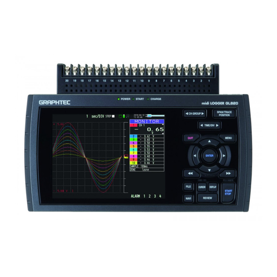
midi LOGGER
GL820
Thank you for choose the midi LOGGER GL820.
This Quick Start Guide describes the basic operations.
Please refer to the manual (PDF) in the CD-ROM for more information.
Checking the Outer Casing
After unpacking, check the GL820's Exterior to make sure that
there are crack or other damage before use.
Checking the Accessories
o Quick Start Guide : 1
o CD-ROM : 1
o AC cable/AC adapter : 1
Setting and Checking the AC Line Frequency
Set the AC line frequency in the "OTHR" menu. This setting
(50 or 60 Hz) affects the noise reduction performance of the device.
Quick Start Guide
Don't forget to
check the setting
GL820-UM-851
Advertisement
Table of Contents

Related Manuals for GRAPHTEC GL820-UM-851


Summary of Contents for GRAPHTEC GL820-UM-851
- Page 1 LOGGER GL820 Quick Start Guide GL820-UM-851 Thank you for choose the midi LOGGER GL820. This Quick Start Guide describes the basic operations. Please refer to the manual (PDF) in the CD-ROM for more information. Checking the Outer Casing After unpacking, check the GL820's Exterior to make sure that there are crack or other damage before use.
-
Page 2: Table Of Contents
GL820 Contents Nomenclature................Connection Procedures.............. Precautions to Observe When Performing Measurement ....Descriptions of the Control Panel Keys ........Descriptions of the Menu Screens ..........Measurement Procedure..............1. Preparations : How to Make the Preparations Required for Data Capture .......... -
Page 3: Nomenclature
GL820 Nomenclature Top Panel External input/output terminals -LOGIC/PULSE Analog signal input terminals Power jack for the humidity sensor -EXT TRIG/SAMPLE (Humidity sensor is the option B-530) -ALARM Logic alarm cable is required for connection (Cable is the option B-513) AC adapter jack Connecting the USB memory device Front Panel... -
Page 4: Connection Procedures
GL820 Connection Procedures Connecting the AC Adapter Connecting the Grounding Cable Connect the DC output of the AC adapter to the Use a flathead screwdriver to push the button above the GND terminal while connecting the grounding cable to the connector indicated as "DC LINE"... -
Page 5: Precautions To Observe When Performing Measurement
Precautions to Observe When Performing Measurement Maximum input voltage If a voltage exceeding the specified value is input, the semiconductor relay in the input section will be damaged. Never input a voltage exceeding the specified value even for a moment. <Between +/–... -
Page 6: Descriptions Of The Control Panel Keys
GL820 Descriptions of the Control Panel Keys (2) SPAN/POSI/TRACE (1) CH GROUP (3) TIME/DIV (5) QUIT (4) MENU (6) DIRECTION KEYS + ENTER (7) ENTER Password setting (8) FAST FORWARD (KEY LOCK) (13) FILE (9) START/STOP (USB DRIVE MODE) (14) NAVI (11) DISPLAY (12) CURSOR (10) REVIEW... - Page 7 MENU Press the MENU key to open a setup menu. Each time this key is pressed, the setup screen tabs change in the sequence shown below. - AMP Settings Used to set the input, range, filter and other settings. - Data Capture Settings DATA Used to set settings such as the sampling interval, data capture destination, and calculations during data capture.
- Page 8 START/STOP (USB DRIVE MODE) Press the START/STOP key to perform start and stop of a data capture while the GL820 is in the Free Running status. If this key is held down while the power to the GL820 is turned on, the GL820 goes into USB Drive Mode.
-
Page 9: Descriptions Of The Menu Screens
GL820 Descriptions of the Menu Screens 4.Device access lamp 5.Remote lamp 3.Status mark 6.Key lock lamp 2.Time/DIV display area 1.Status message display area 8.AC/Battery status indicator 7.Clock display 18.Data capture bar 9.Waveform operation display area 17.Scale upper limit 10.Digital display area 16.Waveform display area 11.Quick settings 15.Scale lower limit... -
Page 10: Measurement Procedure
GL820 Measurement Procedure In this section we will provide a simple explanation of the data capture procedure: Preparations -> Setup -> Data Capture -> Data Replay. Voltage measurement is performed here. Purpose of data capture : To measure the temperature of the target objects Temperature Range : T Thermocouple Voltage range... -
Page 11: Setup: How To Make The Settings
2. Setup: How to Make the Settings Make the settings required for data capture. Here we will make only those settings that are minimum requirement. The other settings will be not changed from the factory default settings. Basic Setup Menu Operation key, the ENTER key, and the QUIT key are used to set the condition on the setup menu. - Page 12 4. Press the MENU key and open the "DATA" menu. 5. Set the sampling interval to "1s". Move the cursor to "Sampling" and then select "1s". 6. Set the Data Capture Destination to "Internal memory". Here the "TEST" folder is created in the Internal memory device, and then destination for the captured data is set to the TEST folder.
- Page 13 (6) Return to screen (2) and move the cursor to the icon to select the created folder and then press the ENTER key. (7) Move the cursor to and then press the ENTER key. When this setting has been completed, data will be captured and saved to the <TEST>...
-
Page 14: Data Capture: How To Capture Data
3. Data Capture: How to Capture Data All of setting for the data capture have been set, capturing data can be started now. During the data capture operation, let's also replay some data that was captured previously. 1. Starting data capture (1) Press the START/STOP key. -
Page 15: Data Replay : How To Replay Captured Data
4. Data Replay : How to Replay Captured Data When data capture ends, data is automatically replayed. The automatically replayed data is the data captured to the internal memory which has been set as the data capture destination. Press the QUIT key to end the data replay operation. 1.Selecting a file to replay (1) Press the REVIEW key. -
Page 16: Convenient Functions
GL820 Convenient Functions The GL820 has various functions that enable it to be used more effectively. The selected three functions are described with details in the following. Trigger Functions to Control Data Capture Start/Stop Operations Trigger functions can be used to control the timing of the start of a data capture operation, and the timing of the end of a data capture operation. - Page 17 (4) Move the cursor to the "Level" parameter next to the "Mode" parameter and then press the ENTER key. (5) The input box shown in the following screen is displayed. Select "20". Use the keys to move to the cursor to the second digit from the right, and the keys to change the value.
-
Page 18: Span, Position And Trace Functions To Adjust The Waveform Display
Span, Position and Trace Functions to Adjust the Waveform Display These functions enable to make adjustments in order to view individual channels more easily, and to delete waveforms that is not required to view in display. Points to The span, position and trace operations can be performed while the GL820 Remember is in the Free Running status, while it capturing data, and while it is replaying data. -
Page 19: Specifications
GL820 Specifications Standard Specifications Item Description Number of analog channel 20 channels in standard configuration, up to 200 channels using the extension unit External input and Trigger input and External sampling (1ch), output functions Logic input (4ch) or Pulse input (4ch), Alarm output (4ch) PC interface Ethernet (10BASE-T/100BASE-TX), USB (HighSpeed supported) provided as standard features Built-in memory... -
Page 20: Input Unit Specifications
Input Unit Specifications Item Description Number of input channels M3 screw type, 20 channels (maximum 200 channels with extension unit) Method Photo MOS relay scanning system, all channels isolated, balanced input 10ms/1ch Maximum sampling speed 20m/50m/100m/200m/500m/1/2/5/10/20/50/1-5V F.S. Voltage Thermocouple : K、J、E、T、R、S、B、N、W(WRe5-26) Measurement Temperature Resistance temperature detector... -
Page 21: Installation Guide
GL820 APS Installation Guide This guide describes how to install the GL820 application software. System Requirements This software can be installed on a PC which fulfills the following conditions. : WindowsXP, WindowsVista, Windows 7 : Pentium4 1.7GHz or higher Memory : 256MB or more (512MB or more recommended) : 200MB (1GB recommended) additional space required for installing the application software... - Page 22 Specifications are subject to change without notice. May 1, 2010 GL820 Quick Start Guide 1st edition-01 (GL820-UM-851) Publisher GRAPHTEC CORPORATION...
Need help?
Do you have a question about the GL820-UM-851 and is the answer not in the manual?
Questions and answers