GRAPHTEC GL840 Quick Start Manual
Midi logger
Hide thumbs
Also See for GL840:
- User manual (208 pages) ,
- Quick start manual (24 pages) ,
- Quick start up manual (24 pages)
Table of Contents
Advertisement
Advertisement
Table of Contents

Related Manuals for GRAPHTEC GL840


Summary of Contents for GRAPHTEC GL840
- Page 1 LOGGER GL840 Quick Start Guide 604849025 GL840-UM-854...
-
Page 2: Table Of Contents
This Quick Start Guide describes the basic operations. Please refer to the manual (PDF) in the CD-ROM for more information. Checking the Outer Casing After unpacking, check the GL840's Exterior to make sure that there are crack or other damage before use. Checking the Accessories •... -
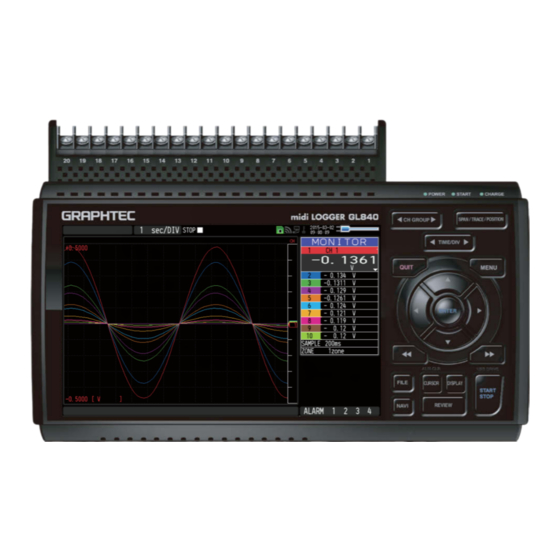
Page 3: Nomenclature
Nomenclature Analog signal input terminals Top View Power jack for humidity sensor • Standard terminal (B-564) Humidity sensor • Withstand high-voltage high-precision terminal (Option: when using the B-530) (B-565) • Screwless terminal (B-564SL) Wireless unit connection terminal Wireless unit (Option: When using B-568) SD CARD GND terminal GS sensor and terminal/... -
Page 4: Connection Procedures
Use a flathead screwdriver to push the button above connector indicated as "DC LINE" on the GL840. the GND terminal while connecting the grounding cable to the GL840. Connect the other end of the cable to ground. Making Connections to the Analog Input Terminals... - Page 5 * Make sure that the SD CARD is not locked. CAUTION: When removing the SD CARD, remove it after the SD CARD on the GL840's screen is displayed in green. The POWER LED blinks while accessing to the SD CARD.
-
Page 6: Precautions To Observe When Performing Measurement
GL840 requests to have approximately 30 minutes warm-up in order to have the specified performance. Unused channels The analog input section of the GL840 contains a capacitor to improve the noise removal capability. Therefore, when the input terminal is open, the measurement result may be affected by the signals of other channels. - Page 7 Ex 3 : Operate GL840 with batteries (Option: B-569). Ex 4 : In the AMP settings menu, set filter to any setting other than "OFF". Ex 5: The digital filter of the GL840 provides an effective sampling interval. (Table below)
-
Page 8: Descriptions Of The Control Panel Keys
Used to change trace settings (set the waveform display to On or Off). TRACE * If the QUIT key is pressed when the GL840 is in the SPAN, TRACE, or POSITION mode, the display returns to MONITOR mode. . TIME/DIV Press the [TIME/DIV] key to change the time axis display range on the waveform screen. - Page 9 . MENU Press the [MENU] key to open a setup menu. Each time this key is pressed, the setup screen tabs change in the sequence shown below. Points to Remember • AMP Settings Used to set the input, range, filter and other settings. •...
- Page 10 GL840 is in the Free Running, and the capturing stop operation is performed while it is in data capturing. If this key is held down while the power to the GL840 is turned on, the GL840 is switched the USB to the Drive Mode.
-
Page 11: Descriptions Of The Menu Screens
(wired LAN) Remote terminal recognized display (wireless sensor/remote terminal) which are Remote terminal connecting to the GL840 is displayed.) unrecognized display : Displays the remote status. (Colored = Wireless sensor Remote lamp recognized display remote status)... -
Page 12: Measurement Procedure
Quick settings : Displays items that can be easily set. The keys can be used to make a Quick settings item active, and the keys to change the values. Alarm display area : Displays the status of the alarm output. (Red = alarm generated) Pen display : Displays the signal positions, trigger positions, and alarm ranges for each... -
Page 13: Setup : How To Make The Settings
2. Setup : How to Make the Settings Make the settings required for data capture. Here we will make only those settings that are minimum requirement. The other settings will be not changed from the factory default settings. Points to Remember Basic Setup Menu Operation , [ENTER], and [QUIT] keys are used to set the condition on the setup menu. - Page 14 4. Press the [MENU] key and open the "DATA" menu. Press the [MENU] key. Next, move the cursor to the “DATA” in the "MENU" at the top. 5. Set the sampling interval to "1s". Move the cursor to "Sampling" and then select "1s". 6.
- Page 15 (4) Go to the "SD1" level using the key. Move the cursor to the [Create new folder] icon using the keys and then press the [ENTER] key. The Input menu is displayed. (5) A text input box is displayed. Let's create a folder named "TEST". (1) In the text type select;...
-
Page 16: Data Capture : How To Capture Data
Press the [START/STOP] key to end the data capture operation. (1) Press the [START/STOP] key. (2) A confirmation message is displayed. Press the [ENTER] key. (3) Data capture ends, and the GL840 goes into the Free Running status. The operation of data capture is completed. -
Page 17: Data Replay : How To Replay Captured Data
A confirmation message is displayed. Press the [ENTER] key. Data replay ends, and the GL840 goes into the Free Running status. Explanation of basic operation in the GL840 is completed. The GL840 has many other convenient functions. Please refer the next five pages for details. -
Page 18: Convenient Functions
Convenient Functions The GL840 has various functions that enable it to be used more effectively. The selected three functions are described with details in the following. Trigger Functions to Control Data Capture Start/Stop Operations 1. Starting data capture Trigger functions can be used to control the timing of the start of a data capture operation, and the timing of the end of a data capture operation. - Page 19 GL840 to the Free Running status. (8) Press the [START/STOP] key to start data capture. If the trigger condition has not been satisfied, the GL840 goes into the "Armed" status as shown on the following screen. When the trigger condition is satisfied, the recording is started after the display is changed to the “Data capture SD card 1”...
-
Page 20: Span, Trace And Position Functions To Adjust The Waveform Display
Points to Remember The span, trace and position operations can be performed while the GL840 is in the Free Running status, while it is capturing data, and while it is replaying data. -
Page 21: Specifications
Specifications Standard Specifications Item Description Number of analog channel GL840-M or GL840-WV (Up to 200ch can be used with 20ch/1 terminal or expansion unit, remote terminal) External input and Trigger input and External sampling (1ch), output functions Logic input (4ch) or Pulse input (4ch), Alarm output (4ch) -
Page 22: Common Specifications Of The Terminal In The Input Section
Common Specifications of the terminal in the input section * The following specifications are common to GL840-M and GL840-WV. Item Description Number of input channels M3 screw type, 20 channels (maximum 200 channels with extension unit) Method Photo MOS relay scanning system, all channels isolated, balanced input... -
Page 23: Specifications Of Input Section (Gl840-Wv Withstand High Voltage High-Precision Terminal)
Between input terminal/input terminal : 600Vp-p/1 minute Between input terminal/GND : 2300 VACrms/1 minute Installation Guide For the install procedure of the GL840 application software (USB driver / GL100_240_840-APS), refer to the “Application Software Manual” included in the attached CD-ROM. - Page 24 Specifications are subject to change without notice. January 5, 2021 GL840 Quick Start Guide 1st edition-01 (GL840-UM-854) Publisher GRAPHTEC CORPORATION...
Need help?
Do you have a question about the GL840 and is the answer not in the manual?
Questions and answers