Table of Contents
Advertisement
Quick Links
Advertisement
Table of Contents

Related Manuals for GRAPHTEC GL100


Summary of Contents for GRAPHTEC GL100
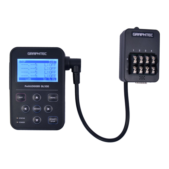
- Page 1 Petit LOGGER GL100-UM-251 SERVICE MANUAL GL100-UM-251-01-9370...
- Page 3 HISTORY OF REVISIONS No. Date issued Description of revision Page Edition 14.09.25 First Printing GL100-UM-251-9370...
- Page 4 TO ENSURE SAFETY This Service Manual has been compiled for the purpose of facilitating repair and maintenance of the GL100 LOGGER by Graphtec service personnel and other persons who have undergone equivalent technical training. Maintenance or repair by unauthorized service personnel is to be strictly avoided. Because the GL100 contains numerous internal components with a high electric potential, such work by unauthorized service personnel could cause human injury or serious damage to the GL100 LOGGER.
-
Page 5: Table Of Contents
2.1 Preparations to upgrade the firmware ................ 2-1 2.2 How to upgrade the Main firmware ................2-1 2.3 How to upgrade the Sub firmware for the GL100-WL model ........2-7 2.4 How to confirm the firmware version ................ 2-13 3 DISASSEMBLY AND REASSEMBLY ...........3-1 3.1 Notes on Disassembly and Reassembly .............. - Page 6 The internal memory operation inspection ..............5-39 6 PARTS LISTS ..................6-1 6.1 Recommended Parts List ..................... 6-1 6.2 Parts Lists ........................6-2 6.2.1 Main Unit (GL100-WL/-N) .......................6-2 6.2.2 GS-4VT (Voltage Temperature Sensor) ................6-3 6.2.3 GS-4TSR (Thermistor Sensor) .................... 6-3 6.2.4...
-
Page 7: Configuration
AC Current Sensor Adapter GS-DPA-AC Sensor Extension Adapter GS-DPA Sensor Extension Cable GS-EXC AC Clamp Sensor 50A GS-AC50A AC Clamp Sensor 100A GS-AC100A AC Clamp Sensor 200A GS-AC200A Thermistor Sensor (MAX105ºC) GS-TSR-4P MAX105ºC, 4 PCS Thermistor Sensor (MAX125ºC) GS-TSR-125-4P MAX125ºC, 4 PCS GL100-UM-251-9370... - Page 8 1 CONFIGURATION GL100-UM-251-9370...
-
Page 9: Upgrading The Firmware
GL100_Main_V***.hxf Sub firmware: GL100_WebImage_V***.bin (The sub firmware is used for the wireless part of GL100-WL model. This file is not updated always. And this file is not used to the GL100-N model.) 2.2 How to upgrade the Main firmware How to upgrade The firmware file send to the GL100 via the USB port of PC. - Page 10 2 UPGRADING THE FIRMWARE (2) Connect the GL100 and the PC via USB port by using the USB cable. (3) The following menu is displayed when the power was applied. (The following menu is displayed when the 4TSR is connected to the GL100 as example.)
- Page 11 L : OFF 25.55 C L : OFF S:30:0s (5) Run the "GL100-Network congfig.exe" on the PC. (6) The following menu is displayed on the PC. (7) Press the [Update the GL100] button, and then the following menu is displayed. GL100-UM-251-9370...
- Page 12 2 UPGRADING THE FIRMWARE (8) Press the [Search] button to select the GL100. (9) Select the [Firm Ware] radio button to update the firmware. (10) Press the [File] button to select the firmware file which was copied on the PC.
- Page 13 (11) Select the firmware file, and then press the [Open] button. (12) Press the [Start Update] button to write the firmware file to the GL100. (13) The Progress bar shows the writing process when it is sending the firmware to the GL100. GL100-UM-251-9370...
- Page 14 (14) The following menu is displayed when after the writing process was finished. (15) Press the [QUIT] key and hold for a few seconds. (16) The Staring menu displays on LCD of GL100. (17) Close the "GL100-Network congfig.exe" on the PC.
-
Page 15: How To Upgrade The Sub Firmware For The Gl100-Wl Model
Update the sub-firmware only for the GL100-WL when it was updated. This does not need to perform for the GL100-N. (1) Connect the sensor module to the GL100-WL. (It doesn't matter which sensor module connected.) (2) Connect the GL100 and the PC via USB port by using the USB cable. - Page 16 2 UPGRADING THE FIRMWARE (3) The following menu is displayed when the power was applied. (The following menu is displayed when the 4TSR is connected to the GL100 as example.) GL100-4TSR Sleeping!! ENTER key to start QUIT key to power off (4) Press the [ENTER] key to display the following menu.
- Page 17 2 UPGRADING THE FIRMWARE (6) The following menu is displayed on the PC. (7) Press the [Update the GL100] button, and then the following menu is displayed. (8) Press the [Search] button to select the GL100. GL100-UM-251-9370...
- Page 18 (9) Select the [Web Image] radio button to update the sub-firmware. (10) Press the [File] button to select the sub-firmware file which was copied on the PC. (11) Select the sub-firmware file, and then press the [Open] button. GL100-UM-251-9370 2-10...
- Page 19 (12) Press the [Start Update] button to write the sub-firmware file to the GL100. (13) The Progress bar shows the writing process when it is sending the sub-firmware to the GL100-WL. (14) The following menu is displayed when after the writing process was finished.
- Page 20 2 UPGRADING THE FIRMWARE (15) Press the [QUIT] key and hold for a few seconds. (16) The Staring menu displays on LCD of GL100. (17) Close the "GL100-Network congfig.exe" on the PC. GL100-UM-251-9370 2-12...
-
Page 21: How To Confirm The Firmware Version
2.4 How to confirm the firmware version (1) Connect the sensor module to the GL100. (It doesn't matter which sensor module connected.) (2) Apply the power to the GL100 (Install the Battery or apply the power from the USB bus power.) (3) Press the [ENTER] key. - Page 22 25.55 C L : OFF S:30:0s (5) The firmware version is shown at the Body information. [INFORMATION] 10/10 Type Version Body: 1.00/1.00 Sensor1: 4TSR 1.00 Sensor2: ------- --.-- (6) Press the [QUIT] key to return to the measuring menu. GL100-UM-251-9370 2-14...
-
Page 23: Disassembly And Reassembly
(1) Remove the M2L5 binding head screw holding the battery cover. (2) Detach the battery cover from the main unit. Main Unit Battery cover M2L5 binding head screw Re-assembly (1) Re-assemble the battery cover in the reverse order in which it was disassembled. GL100-UM-251-9370... -
Page 24: Removing The Rear Case Assembly
(3) Disconnect the battery cable from the main control board 1. (4) Detach the rear case assembly from the main unit. Main unit Rear case assembly M2L5 binding head screw Battery cable Re-assembly (1) Re-assemble the rear case assembly in the reverse order in which they were disassembled. GL100-UM-251-9370... -
Page 25: Removing The Main Control Board 2
(5) Detach the main control board 2 from the main unit. Key switch sheet flexible cable Main unit Main control board 2 M2L5 binding head screw LCD flexible cable Re-assembly (1) Re-assemble the main board 2 in the reverse order in which it was disassembled. GL100-UM-251-9370... -
Page 26: Removing The Control Panel Board 1
(4) Remove the two M2L7 spacer screws holding the main control board 1. (5) Detach the main control board 1 from the main unit. Main unit Main control board 1 M2L7 Spacer Screw Re-assembly (1) Re-assemble the main control board 1 in the reverse order in which it was disassembled. GL100-UM-251-9370... -
Page 27: Removing The Lcd
(3) Detach the main control board 2 from the main unit (See Section 3.4). (4) Detach the main control board 1 from the main unit (See Section 3.5). (5) Detach the LCD. Re-assembly (1) Re-assemble the LCD in the reverse order in which it was disassembled. GL100-UM-251-9370... -
Page 28: Replacing The Key Switch Sheet
Key switch sheet Re-assembly (1) Remove and clean the double-stick tape glue from the front case. (2) Put the key switch sheet on the front case. (3) Re-assemble the front case in the reverse order in which it was disassembled. GL100-UM-251-9370... -
Page 29: Setup Procedures
(1) Connect the sensor module to the GL100. (It doesn't matter which sensor module connected.) (2) Take out the Micro SD Card from the GL100 if it is installing. (3) Apply the power to the GL100 (Install the Battery or apply the power from the USB bus power.) GL100-UM-251-9370... - Page 30 4 SETUP PROCEDURES (4) The following menu is displayed when the power was applied. (The following menu is displayed when the 4TSR is connected to the GL100 as example.) GL100-4TSR Sleeping!! ENTER key to start QUIT key to power off (5) Press the [ENTER] key to display the following menu.
- Page 31 LCD Brightness : Mid Language : English Factory INIT : (7) Move the cursor to the “Factory INIT” position using the [Direction] keys. 8/10 [OTHER-1] Date/Time: Screen Sav : Off LCD Brightness : Mid Language : English Factory INIT : GL100-UM-251-9370...
- Page 32 No : QUIT (9) Press the [ENTER] key, and then the following menu is displayed in a few second after the initialization is finished. 8/10 [OTHER-1] Date/Time: Screen Sav : Off LCD Brightness : Mid Language : English Factory INIT : GL100-UM-251-9370...
-
Page 33: Gs-4Vt Module Setup
• Have a voltmeter that can confirm the output voltage from the voltage generator. Wiring connection Voltmeter (for confirming the output voltage of voltage generator) Voltage generator GS-4VT Input cable Input a voltage to CH1. GL100 USB AC Adapter GL100-UM-251-9370... - Page 34 (1) As shown in the figure above, connect the output of the voltage generator to the GS-4VT’s CH1 input terminal. (2) Leave the GL100 turned on for at least minutes. (3) The following menu is displayed when the power was applied.
- Page 35 (5) The following menu is displayed. Select the [Volt ], and then press the [ENTER] key. [V&TEMP Set Up] Set UP: TEMP Volt (6) The following menu is displayed. GND(0.000mV) Start to execure (7) Input “0.000mV” to the input terminals of channel 1. GL100-UM-251-9370...
- Page 36 +0.000000 mV 20 mV +20.00000 mV 50 mV +50.00000 mV 100 mV +100.0000 mV 200 mV +200.0000 mV 500 mV +500.0000 mV +1.00000 V +2.00000 V 5.00000 V 10 V 10.0000 V 20 V 20.0000 V 50 V 50.0000 V GL100-UM-251-9370...
- Page 37 (12) When you have finished the Setup operation for 50 V, the "Save the setting?" message appears. Press the [ENTER] key to save the new Setup data to the GS-4VT. [ V&TEMP Set Up ] Save the settings? Yes:ENTER / No:QUIT GL100-UM-251-9370...
- Page 38 [V&TEMP Set Up] Set UP: TEMP Volt (14) Press the [QUIT] key to finish the setup mode. GL100-4VT Sleeping!! ENTER key to start QUIT key to power off (15) Perform the temperature setup for the GS-4VT after the voltage setup was performed.
-
Page 39: Setup Procedure For Temperature
(K) input side (T) output side: Short (T) input side 0˚C reference temperature device (Zero Controller) (T) compensation lead Φ0.32 Connect (T) compensation lead to the CH3 and CH4 input terminals. Connect (K) compensation lead to the CH2 input terminals. GL100-UM-251-9370 4-11... - Page 40 Setup procedure (1) As shown in the figure above, connect the inputs of the zero controller to the GS-4VT’s input terminals. (2) Leave the GL100 turned on for at least minutes. (3) The following menu is displayed when the power was applied.
- Page 41 ], and then press the [ENTER] key. [V&TEMP Set Up] Set UP: TEMP Volt (6) The following menu is displayed. TEMP Start to execure (7) Confirm the wiring which cables are connecting to the terminals of GS-4VT shown in the wiring diagram above. GL100-UM-251-9370 4-13...
- Page 42 4 SETUP PROCEDURES (8) Press the [START/STOP] key. TEMP Start to execure (9) Press the [ENTER] key when the following menu was displayed. [ V&TEMP Set Up ] Save the settings? Yes:ENTER / No:QUIT GL100-UM-251-9370 4-14...
- Page 43 (10) The following menu is displayed, after the setup parameters have been registered to the GS-4VT. [V&TEMP Set Up] Set UP: TEMP Volt (11) Press the [QUIT] key to finish the setup mode. GL100-4VT Sleeping!! ENTER key to start QUIT key to power off This completes the temperature setup. GL100-UM-251-9370...
-
Page 44: Gs-4Tsr Module Setup
The input terminals are open. (It nothing is connected to the terminals.) Setup procedure (1) Connect the GS-4VT to the GL100. (2) Leave the GL100 turned on for at least minutes. (3) The following menu is displayed when the power was applied. GL100-4TSR... - Page 45 4 SETUP PROCEDURES (4) Simultaneously press the and the keys. GL100-4VT Sleeping!! ENTER key to start QUIT key to power off (5) Press the [ENTER] key when the following menu was displayed. [THERM. Set Up] Set UP: GL100-UM-251-9370 4-17...
- Page 46 (It will display from GND and 10 kΩ-1CH, 10 kΩ-2CH, 10 kΩ-3CH, 10 kΩ-4CH automatically.) (8) Press the [ENTER] key when the following menu was displayed. [THERM. Set Up] Save the settings? Yes:ENTER / No:QUIT GL100-UM-251-9370 4-18...
- Page 47 (9) The following menu is displayed, after the setup parameters have been registered to the GS-4TSR. [THERM. Set Up] Set UP: (10) Press the [QUIT] key to finish the setup mode. GL100-4TSR Sleeping!! ENTER key to start QUIT key to power off...
-
Page 48: Gs-3At Module Setup
Attach the GS-3AT on the jig (as shown in the picture below) which is able to put the GS-3AT vertically against from the surface plate. (The surface of surface plate must be horizontal.) Wiring connection Connect the GS-3AT to the GL100. GL100-UM-251-9370 4-20... - Page 49 4 SETUP PROCEDURES Setup procedure (1) Connect the GS-3AT to the GL100. (2) Leave the GL100 turned on for at least minutes. (3) The following menu is displayed when the power was applied. GL100-3AT Sleeping!! ENTER key to start QUIT key to power off...
- Page 50 4 SETUP PROCEDURES (5) Press the [ENTER] key when the following menu was displayed. [3AT Set Up] Set UP: (6) The following menu is displayed. The X axis +1G +0.99 +0.01 -0.01 Yes: ENTER / No: QUIT GL100-UM-251-9370 4-22...
- Page 51 (7) Put the X direction of GS-3AT to upper direction onto the surface plate as shown in the picture below. ↑ X (8) Press the [ENTER] key. The X axis +1G +0.99 +0.01 -0.01 Yes: ENTER / No: QUIT GL100-UM-251-9370 4-23...
- Page 52 (9) The following menu is displayed after the X direction of setup was finished. The Y axis +1G +0.99 +0.01 -0.01 Yes: ENTER / No: QUIT (10) Put the Y direction of GS-3AT to upper direction onto the surface plate as shown in the picture below. ↑ Y GL100-UM-251-9370 4-24...
- Page 53 The Y axis +1G +0.99 +0.01 -0.01 Yes: ENTER / No: QUIT (12) The following menu is displayed after the Y direction of setup was finished. The Z axis +1G +0.01 +1.01 -0.01 Yes: ENTER / No: QUIT GL100-UM-251-9370 4-25...
- Page 54 (13) Put the Z direction of GS-3AT to upper direction onto the surface plate as shown in the picture below. ↑ Z (14) Press the [ENTER] key. The Z axis +1G +0.01 +1.01 -0.01 Yes: ENTER / No: QUIT GL100-UM-251-9370 4-26...
- Page 55 (15) The following menu is displayed after the Z direction of setup was finished. [3AT Set Up] Save the settings? Yes: ENTER / No: QUIT (16) Press the [ENTER] key. (17) The following menu is displayed, after the setup parameters have been registered to the GS-3AT. [3AT Set Up] Set UP: GL100-UM-251-9370 4-27...
- Page 56 4 SETUP PROCEDURES (18) Press the [QUIT] key to finish the setup mode. GL100-3AT Sleeping!! ENTER key to start QUIT key to power off Note There is possibility that the GS-3AT was not put onto the surface plate vertically against from the surface plate when the following menu is displayed during setup.
-
Page 57: Regarding Other Module (Except Gs-4Vt, Gs-4Tsr, Gs-3At)
4 SETUP PROCEDURES 4.5 Regarding other module (Except GS-4VT, GS-4TSR, GS-3AT) There is no setup for the other module. GL100-UM-251-9370 4-29... -
Page 58: Inspection And Check Procedures
-0.5 ˚C to +0.5 ˚C -1.0 ˚C to +1.0 ˚C K range Input voltage precision ratings (Type K) Temperature Input voltage Factory Rating Product Rating 0 ˚C 0.000 mV (Short the input terminal -1.0 ˚C to +1.0 ˚C -1.5 ˚C to +1.5 ˚C GL100-UM-251-9370... -
Page 59: How To Inspect The Gs-4Vt Module Voltage Measurement Precision
• Have a voltmeter that can confirm the output voltage from the voltage generator. Wiring connection Voltmeter (for confirming the output voltage of voltage generator) Voltage generator GS-4VT Input cable Input a voltage to CH1. GL100 USB AC Adapter GL100-UM-251-9370... - Page 60 (1) As shown in the figure above, connect the output of the voltage generator to the GS-4VT’s CH1 input terminal. (2) Leave the GL100 turned on for at least minutes. (3) The following menu is displayed when the power was applied.
- Page 61 Capture DIST: SD Card Free CAPA:3969810 (7) Press the [QUIT] key to display the following measuring menu. STOP 0:05 0.00 V L : OFF 0.00 V L : OFF 0.00 V L : OFF 0.00 V L : OFF S:30:0s GL100-UM-251-9370...
- Page 62 (9) Press the [QUIT] key after set the AMP settings. Then the following measuring menu is displayed. STOP 0:05 0.00 V L : OFF 0.00 V L : OFF 0.00 V L : OFF 0.00 V L : OFF S:30:0s GL100-UM-251-9370...
- Page 63 +19.980 V to +20.020 V +19.970 V to +20.030 V 50 V +50.000 V +49.95 V to +50.05 V +49.93 V to +50.08 V (12) Repeat step (11), and then confirm that each range of measurement precision is within the above product ratings. GL100-UM-251-9370...
-
Page 64: How To Inspect The Gs-4Vt Module Temperature Measurement Precision
(K) input side (T) output side: Short (T) input side 0˚C reference temperature device (Zero Controller) (T) compensation lead Φ0.32 Connect (T) compensation lead to the CH3 and CH4 input terminals. Connect (K) compensation lead to the CH2 input terminals. GL100-UM-251-9370... - Page 65 Measurement procedure (1) As shown in the figure above, connect the inputs of the zero controller to the GS-4VT’s input terminals. (2) Leave the GL100 turned on for at least minutes. (3) Press the [ENTER] key at the following menu.
- Page 66 Capture DIST: SD Card Free CAPA:3969810 (6) Press the [QUIT] key to display the following measuring menu. STOP 0:05 0.00 V L : OFF 0.00 V L : OFF 0.00 V L : OFF 0.00 V L : OFF S:30:0s GL100-UM-251-9370...
- Page 67 TC-T (8) Press the [QUIT] key after set the AMP settings. Then the following measuring menu is displayed. STOP 0:05 0.00 V L : OFF +0.1C L : OFF -0.1C L : OFF +0.2C L : OFF S:30:0s GL100-UM-251-9370 5-10...
- Page 68 -1.0 ˚C to +1.0 ˚C K range Input voltage precision ratings (Type K) Temperature Input voltage Factory Rating Product Rating 0 ˚C 0.000 mV (Short the input terminal -1.0 ˚C to +1.0 ˚C -1.5 ˚C to +1.5 ˚C GL100-UM-251-9370 5-11...
-
Page 69: Gs-4Tsr Module Measurement Precision Inspection
(1) As shown in the figure above, connect the 10kΩ (±0.1%) resistances to the each channels of the GS- 4TSR’s input terminal. (2) Press the [ENTER] key at the following menu. GL100-4TSR Sleeping!! ENTER key to start QUIT key to power off... - Page 70 L : OFF 25.55 C L : OFF S:30:0s (4) Set the sampling speed to the 1s in the DATA menu. [DATA] Set the Sampling speed to "1s". Sampling: 30s Capture Mode: CONT. Capture DIST: SD Card Free CAPA:3969810 GL100-UM-251-9370 5-13...
- Page 71 (6) Confirm temperature of each channels are showing the 25±0.2 ˚C, which is product rating. STOP 0:05 Confirm temperature 25.03 C L : OFF 25.01 C L : OFF of each channels are 24.95 C L : OFF showing the 25±0.2 ˚C. 25.10 C L : OFF S:30:0s GL100-UM-251-9370 5-14...
-
Page 72: Gs-3At Module Measurement Precision Inspection
Attach the GS-3AT on the jig (as shown in the picture below) which is able to put the GS-3AT vertically against from the surface plate. (The surface of surface plate must be horizontal.) Wiring connection Connect the GS-3AT to the GL100. GL100-UM-251-9370 5-15... - Page 73 5 INSPECTION AND CHECK PROCEDURES Measurement procedure (1) As shown in the figure above, connect the GS-3AT module. (2) Press the [ENTER] key at the following menu. GL100-3AT Sleeping!! ENTER key to start QUIT key to power off (3) Press the [MENU] key two times to display the DATA menu.
- Page 74 Sampling: 1s Set the "SAMP.Mode" to the "AVE.". SAMP. Mode: AVE. Capture DIST: SD Card Free CAPA:3969810 (5) Press the [QUIT] key to display the following measuring menu. STOP 0:05 MODE: DIR. +28.64 C +0.07G +0.01G +0.99G S:30:0s GL100-UM-251-9370 5-17...
- Page 75 (6) Press the [MENU] key to display the AMP menu. And then set the XYZ of range (G) to the 2. [AMP] 1/10 Set the XYZ of range (G) Range(G) to the 2G. XYZ: 2 (7) Press the [QUIT] key to display the following measuring menu. STOP 0:05 MODE: DIR. +28.64 C +0.07G +0.01G +0.99G S:30:0s GL100-UM-251-9370 5-18...
- Page 76 +0.99G within from 0.96 to 1.04. +0.01G +0.01G S:30:0s (10) Put the Y direction of GS-3AT to upper direction onto the surface plate as shown in the picture below. ↑ Y GL100-UM-251-9370 5-19...
- Page 77 +0.01G rating if it is showing +0.99G within from 0.96 t0 1.04. +0.01G S:30:0s (12) Put the Z direction of GS-3AT to upper direction onto the surface plate as shown in the picture below. ↑ Z GL100-UM-251-9370 5-20...
-
Page 78: Gs-3At Module Temperature Measurement Precision Inspection
When measuring the temperature, keep the GS-3AT and the temperature gauge in the same environment at least 10 minutes until the both temperature sensors are sensing the stable temperature. Temperature precision Measuring range -10≤TS≤50 ±1.0±ºC -10ºC to 50ºC GL100-UM-251-9370 5-21... -
Page 79: Gs-Co2 Module Measurement Precision Inspection
GS-CO2 does not have the forced intake system for the air when it is comparing by the gauge which has the forced intake system. (Recommended CO2 concentration monitor: Riken Keiki RI-85) CO2 concentration precision Measuring range ±(+5% of rdg +30ppm) 0ppm to 9999ppm GL100-UM-251-9370 5-22... - Page 80 5 INSPECTION AND CHECK PROCEDURES Measurement procedure (1) As shown in the figure above, connect the GS-CO2 module to the GL100. (2) Press the [ENTER] key at the following menu. GL100-CO2 Sleeping!! ENTER key to start QUIT key to power off (3) Press the [MENU] key two times to display the DATA menu.
- Page 81 Capture DIST: SD Card Free CAPA:3969810 (5) Press the [QUIT] key to display the following measuring menu. And then confirm the CO2 concentration measured is within the rating. STOP 0:05 CO2: Confirm the CO2 concentration measured is within the rating. S:30:0s GL100-UM-251-9370 5-24...
-
Page 82: Gs-Dpa-Ac Module Measurement Precision Inspection
AC current clamp meter to compare the AC current. Clamp the sensors to the AC 100V 50Hz power line cable to measure the AC current. AC current measurement precision ±2.0% of F.S. ±1 digit Ambient temperature 23°C, Rated input, Rated frequency GL100-UM-251-9370 5-25... - Page 83 5 INSPECTION AND CHECK PROCEDURES Measurement procedure (1) As shown in the figure above, connect the GS-DPA-AC module to the GL100. (2) Press the [ENTER] key at the following menu. GL100-AC Sleeping!! ENTER key to start QUIT key to power off (3) Press the [MENU] key three times to display the DATA menu.
- Page 84 Set the Sampling speed to "1s". Sampling: 1s Capture DIST: SD Card Free CAPA:3969810 (5) Press the [QUIT] key. (6) Press the [MENU] key to display the AMP menu. STOP 0:05 (A): 0.00A PWR: 0.00KW (A): 0.00A PWR: 0.00KW S:30:0s GL100-UM-251-9370 5-27...
- Page 85 (8) Press the [QUIT] key to display the following measuring menu. And then confirm the measurement AC currents are within the rating. STOP 0:05 (A): 0.00A Confirm the measurement AC PWR: 0.00KW currents are within the rating. (A): 0.00A PWR: 0.00KW S:30:0s GL100-UM-251-9370 5-28...
-
Page 86: Gs-Lxuv Module Measurement Precision Inspection
UV POWER METER: C9536-01 (Hamamatsu Photonics K.K. ) LV checker: LC-5 (Tsubosaka Electric Co.,Ltd.) Recommended light source UV-LED spot light source LC-L1V3 LIGHTNINGCURE L11921 (Hamamatsu Photonics K.K. ) UV LED CONTROLLER: C11924-101 (Hamamatsu Photonics K.K. ) Viewer light source: VLB-10 (Tsubosaka Electric Co.,Ltd.) GL100-UM-251-9370 5-29... -
Page 87: Gs-Th Module Measurement Precision Inspection
Measuring range -20≤TS<0 ±0.8 (ºC) -20ºC to 85ºC 0≤TS≤60 ±0.5 (ºC) 60<TS≤85 ±1.0 (ºC) Humidity precision Measuring range 25ºC 0 to 100% RH 0≤ RH<10 ±10 (%) 10≤RH<20 ±8 (%) 20≤TS≤80 ±5 (%) 80<TS≤90 ±8 (%) 90<TS≤100 ±10 (%) GL100-UM-251-9370 5-30... -
Page 88: Gs-Dpa Module Operation Inspection
GS-DPA GS-CO2 GL100 Confirming Procedure (1) As shown in the figure above, connect the GS-CO2, the GS-TH and the GS-DPA module to the GL100. (2) The following menu is displayed after the power was applied to the GL100. GL100-CO2+TH Sleeping!! - Page 89 CO2 concentration are displaying in the measurement menu. Measurement temperature: Almost room temperature Measurement CO2 concentration: 400 to 1500ppm STOP 0:05 TEMP: +26.86C Measurement temperature: HUM: +39.5% Almost room temperature DEWP: +12.22C Measurement CO2 concentration: CO2: 825ppm 400 to 1500ppm S:30:0s GL100-UM-251-9370 5-32...
-
Page 90: Gl100 Operation Inspection
This is performing to confirm the key and the LED operation. How to confirm the key and the LED operation (1) Connect the sensor module to GL100 to display the menu. (It does not care which sensor module is connected.). - Page 91 5 INSPECTION AND CHECK PROCEDURES (4) The following menu is displayed when the power was applied. (The following menu is displayed when the GS-4TSR module is connected as example.) GL100-4TSR Sleeping!! ENTER key to start QUIT key to power off...
- Page 92 (7) Press the any keys then the black circles corresponding are disappeared. The following menu is displayed when the all keys are pressed. The keys are working normally when the following menu is displayed after the all keys are pressed. GL100-4TSR Sleeping!! ENTER key to start...
-
Page 93: The Micro Sd Card Operation Inspection
This is performing to confirm the capacity of micro SD card is displayed. How to display the capacity of micro SD card (1) Connect the sensor module to GL100 to display the menu. (It does not care which sensor module is connected.). - Page 94 5 INSPECTION AND CHECK PROCEDURES (4) The following menu is displayed when the power was applied. (The following menu is displayed when the GS-4TSR module is connected as example.) GL100-4TSR Sleeping!! ENTER key to start QUIT key to power off (5) Press the [ENTER] key to display the following menu, and then press the [MENU] key three times to display the DATA menu.
- Page 95 (6) The capacity of micro SD card is displayed as shown in the menu below. The micro SD card is working normally when the capacity of micro SD card does show not 0. The Micro SD card has not been detected correctly by the GL100 if it is shown 0. [DATA]...
-
Page 96: The Internal Memory Operation Inspection
This is performing to confirm the capacity of internal memory is displayed. How to display the capacity of micro SD card (1) Connect the sensor module to GL100 to display the menu. (It does not care which sensor module is connected.). - Page 97 5 INSPECTION AND CHECK PROCEDURES (4) The following menu is displayed when the power was applied. (The following menu is displayed when the GS-4TSR module is connected as example.) GL100-4TSR Sleeping!! ENTER key to start QUIT key to power off (5) Press the [ENTER] key to display the following menu, and then press the [MENU] key three times to display the DATA menu.
- Page 98 Capture DIST: SD Card Free CAPA:3969810 (7) Move the cursor on the [INT.MEM] by the key to select the internal memory, and then press the [ENTER] key. [DATA] Sampling: 30s INT.MEM Capture Mode: SD Card Capture DIST: Free CAPA: GL100-UM-251-9370 5-41...
- Page 99 The internal memory is working normally when the capacity of internal memory does show not 0. [DATA] 3/10 Sampling: 30s Capture Mode: CONT. It is working normally when the capacity INT.MEM Capture DIST: SD Card of internal memory does show not 0. Free CAPA:1380022 GL100-UM-251-9370 5-42...
-
Page 100: Parts Lists
6 PARTS LISTS 6.1 Recommended Parts List Part No. Part Name Description Q'ty Remarks 795100760 Main Control Board 1, GL100, RN3055-01 for GL100WL 795100761 Main Control Board 2, GL100WL, RN3055-02 for GL100N 795100762 Main Control Board 2, GL100N, RN3055-02 604300040... -
Page 101: Parts Lists
604300040 Sheet Key, GL100 604300010 Front Case, GL100 604300070 Shield rubber, Case 562060020 LCD, GY1203120048FTW1 795100760 Main Control Board 1, GL100, RN3055-01 GL100-WL 795100761 Main Control Board 2, GL100WL, RN3055-02 With wireless module GL100-N 795100762 Main Control Board 2, GL100N, RN3055-02... -
Page 102: Gs-4Vt (Voltage Temperature Sensor)
6.2.2 GS-4VT (Voltage Temperature Sensor) Part No. Part Name Description Q'ty Remarks Rank GS-4VT GS-4VT Voltage Temperature Sensor GS-4VT (Voltage Temperature Sensor) 6.2.3 GS-4TSR (Thermistor Sensor) Part No. Part Name Description Q'ty Remarks Rank GS-4TSR GS-4TSR Voltage Temperature Sensor GS-4TSR (Voltage Temperature Sensor) GL100-UM-251-9370... -
Page 103: Gs-Th (Temperature Humidity Sensor)
6.2.4 GS-TH (Temperature Humidity Sensor) Part No. Part Name Description Q'ty Remarks Rank GS-TH GS-TH Temperature Humidity Sensor GS-TH (Temperature Humidity Sensor) 6.2.5 GS-3AT (Acceleration Sensor) Part No. Part Name Description Q'ty Remarks Rank GS-3AT GS-3AT Acceleration Sensor GS-3AT (Acceleration Sensor) GL100-UM-251-9370... -
Page 104: Gs-Co2 (Co2 Sensor)
6.2.6 GS-CO2 (CO2 Sensor) Part No. Part Name Description Q'ty Remarks Rank GS-CO2 GS-CO2 CO2 Sensor GS-CO2 (CO2 Sensor) 6.2.7 GS-LXUV (Illuminance UV Sensor) Part No. Part Name Description Q'ty Remarks Rank GS-LXUV GS-LXUV Illuminance UV Sensor GS-LXUV (Illuminance UV Sensor) GL100-UM-251-9370... -
Page 105: Gs-Dpa-Ac (Ac Current Sensor Adapter)
Part Name Description Q'ty Remarks Rank GS-DPA-AC GS-DPA-AC AC Current Sensor Adapter GS-DPA-AC (AC Current Sensor Adapter) 6.2.9 GS-DPA (Sensor Extension Adapter) Part No. Part Name Description Q'ty Remarks Rank GS-DPA GS-DPA Sensor Extension Adapter GS-DPA (Sensor Extension Adapter) GL100-UM-251-9370... -
Page 106: Block Diagram
7 BLOCK DIAGRAM 7 Block Diagram GL100N/WL GL100-UM-251-9370... - Page 107 7 BLOCK DIAGRAM GS-4VT GL100-UM-251-9370...
- Page 108 7 BLOCK DIAGRAM GS-4TSR GL100-UM-251-9370...
- Page 109 7 BLOCK DIAGRAM GS-TH/GS-3AT GL100-UM-251-9370...
- Page 110 7 BLOCK DIAGRAM GS-CO2 GL100-UM-251-9370...
- Page 111 7 BLOCK DIAGRAM GS-LXUV GL100-UM-251-9370...
- Page 112 7 BLOCK DIAGRAM GS-DPA-AC GL100-UM-251-9370...
- Page 113 7 BLOCK DIAGRAM GS-DPA GL100-UM-251-9370...
Need help?
Do you have a question about the GL100 and is the answer not in the manual?
Questions and answers