Table of Contents
Advertisement
Quick Links
Operating instructions
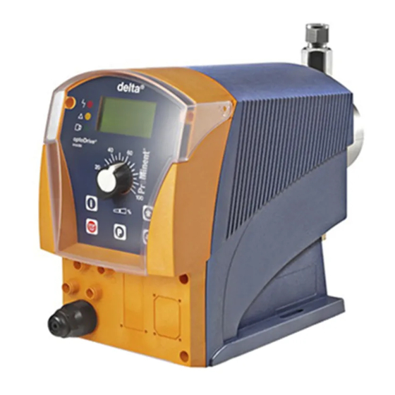
Solenoid Metering Pump
delta
DLTa
®
with controlled optoDrive
®
solenoid drive
EN
P_DE_0002_SW
Please carefully read these operating instructions before use. · Do not discard.
The operator shall be liable for any damage caused by installation or operating errors.
The latest version of the operating instructions are available on our homepage.
Part no. 986691
Original operating instructions (2006/42/EC)
BA DE 036 08/18 EN
Advertisement
Table of Contents

Subscribe to Our Youtube Channel
Related Manuals for ProMinent delta DLTa


Summary of Contents for ProMinent delta DLTa
- Page 1 Operating instructions Solenoid Metering Pump delta DLTa ® with controlled optoDrive ® solenoid drive P_DE_0002_SW Please carefully read these operating instructions before use. · Do not discard. The operator shall be liable for any damage caused by installation or operating errors. The latest version of the operating instructions are available on our homepage.
- Page 2 Supplemental directives Supplementary information Read the following supplementary information in its entirety! You will ben‐ efit more from using the operating instructions should you already know this information. The following are highlighted separately in the document: Enumerated lists Fig. 1: Please read! Instructions ð...
-
Page 3: Table Of Contents
Table of contents Table of contents Identity code..................6 About this pump................9 Safety chapter................10 Storage, transport and unpacking..........15 Overview of equipment and control elements....... 17 5.1 Overview of equipment............17 5.2 Control elements..............18 5.2.1 Key functions..............18 5.2.2 Stroke length adjustment knob........... - Page 4 Table of contents 10.6 Programmable function settings ("Settings" menu ).... 50 10.6.1 Settings for the “Concentration” function (CONCENTRA‐ TION menu)..............51 10.6.2 Settings for the “Auxiliary frequency” function (AUX menu)................58 10.6.3 Settings for the “Flow” function (FLOW menu)....59 10.6.4 Settings for the “Calibration”...
- Page 5 Table of contents Continuous displays..............121 Index.................... 123...
-
Page 6: Identity Code
Connector on discharge side for 8/4 hose, standard on suction side Diaphragm rupture indicator without diaphragm rupture indicator Diaphragm rupture indicator With dual diaphragm system and diaphragm rupture indicator, pres‐ sure sensor Design with ProMinent logo Electrical connection Universal control 100-230 V ±10%, 50/60 Hz... - Page 7 Identity code delta product range, version a ® Cable and plug 2 m European 2 m Swiss 2 m Australian 2 m USA / 115 V 2 m open end Relay no relay Fault indicating 1 x changeover con‐ relay (N/C) tact 230 V –...
- Page 8 Identity code delta product range, version a ® As 3 + PROFIBUS ® inter‐ face, M12 Access code No access code With access code Language German English French Spanish Italian Pause / level Pause N/C, level...
-
Page 9: About This Pump
About this pump About this pump Properties of the device The solenoid metering pumps belonging to the delta ® product range with controlled optoDrive solenoid drive are microprocessor-controlled sole‐ ® noid metering pumps with the following characteristics: Continuous or pulsing operation Adaptation of the pump to the feed chemical Detection of blocked points of injection, broken metering lines and trapped air or gas bubbles in the dosing head by the integral injection... -
Page 10: Safety Chapter
Observe the general limitations with regard to viscosity limits, chem‐ ical resistance and density - see also ProMinent Resistance List in ® the Product Catalogue or at www.prominent.com! All other uses or modifications are prohibited. - Page 11 Service Customer Service department refers to service technicians, who have received proven training and have been authorised by ProMinent or Pro‐ Maqua to work on the system. Safety information WARNING!
- Page 12 An unsuitable feed chemical can damage the parts of the pump that come into contact with the chemical. – Take into account the resistance of the wetted mate‐ rials and the ProMinent Resistance List when selecting the feed chemical - see the ProMinent Product Catalogue or visit ProMinent.
- Page 13 Fixed separating protective equipment Dosing head Housing Hood (houses the control elements) The dosing head may only be removed by the customer in accordance with the "Repair" chapter. The housing and the hood may only be removed by ProMinent customer service department.
- Page 14 Safety chapter Information in the event of an emergency In the event of an electrical accident, disconnect the mains cable from the mains or press the emergency cut-off switch fitted on the side of the system! [Stop/Start] key. If feed chemical exits, switch off the pump by pressing the If necessary depressurise the hydraulic system around the pump.
-
Page 15: Storage, Transport And Unpacking
WARNING! The transporting of pumps which have been used with radioactive feed chemicals is forbidden! They will also not be accepted by ProMinent! WARNING! Only return metering pumps for repair in a cleaned state and with a flushed liquid end - refer to "Decommis‐... - Page 16 Storage, transport and unpacking Scope of delivery Compare the delivery note with the scope of delivery: Metering pump with mains cable Connector kit for hose/pipe connection Product-specific operating instructions with EC Declaration of Con‐ formity Optional accessories Relay cable, as necessary...
-
Page 17: Overview Of Equipment And Control Elements
Overview of equipment and control elements Overview of equipment and control elements 5.1 Overview of equipment P_DE_0027_SW Fig. 2 Control unit Drive unit Liquid end P_DE_0019_SW Fig. 3 Discharge valve Backplate Dosing head Bleed valve Bypass hose sleeve Diaphragm rupture sensor Suction valve... -
Page 18: Control Elements
Overview of equipment and control elements 5.2 Control elements P_DE_0017_SW Fig. 4: a)Displays and keys, b) Electrical control connections LCD screen Stroke length adjustment knob [UP] key [P] key [DOWN] key [STOP/START] key [i] key Operating indicator (green) Warning indicator (yellow) 10 Fault indicator (red) 11 "External control"... -
Page 19: Stroke Length Adjustment Knob
Overview of equipment and control elements Application In continuous displays (operation) In adjustment mode (set up) Pressed 1x Switch between the continuous dis‐ Change between "Change indi‐ plays vidual digits" and "Change one number" Pressed 2x Under "change individual digits": Jump to the first digit Press and hold Change to the secondary display... - Page 20 Overview of equipment and control elements Symbol Additional Name Meaning symbol [STOP/START] key Stop: The pump was stopped using the (therefore manually). Pause: The pump was externally stopped by the Pause contact. Aux: The pump is currently pumping with the auxiliary fre‐ quency as the stroke rate.
- Page 21 Overview of equipment and control elements Symbol Additional Name Meaning symbol ‘Analog’ . The processing 0...20 mA: The pump is in operating mode 0..20 0..20 type ‘0...20’ is set. ‘Analog’ . The processing 4...20 mA: The pump is in operating mode 4..20 4..20 ‘4...20’...
-
Page 22: Functional Description
Functional description Functional description 6.1 Liquid End The dosing process is performed as follows: The diaphragm is pressed into the dosing head; the pressure in the dosing head closes the suction valve and the feed chemical flows through the discharge valve out of the dosing head. -
Page 23: Operating Modes
Functional description The stroke length is adjusted by the stroke length adjustment knob within a range of 0 ... 100 %. A stroke length of between 30 ... 100 %) is recom‐ mended to achieve the specified reproducibility. The stroke rate can be set using the arrow keys (not in "Analog" operating mode) in the range 0 - 200 strokes/min (200 strokes/min ≜12,000 strokes/h). -
Page 24: Relay (Options)
Functional description The following functions are available as standard: "Level switch" function Information about the liquid/powder level in the feed chemical container is reported to the pump. To do so, a two-stage level switch must be fitted; it is connected to the "Level switch" jack. "Pause"... -
Page 25: Lcd Display
Functional description 6.8 LCD display If a fault occurs, the identifier "Fault" appears as well an additional, explan‐ atory symbol. 6.9 LED indicators Fault indicator (red) The fault indicator lights up if the liquid level in the chemical feed container falls below the second switching point of the level switch (20 mm residual filling level in the chemical feed container). -
Page 26: Assembly
Assembly Assembly Compare the dimensions on the dimension sheet – with those of the pump. WARNING! Danger of electric shock If water or other electrically conducting liquids penetrate into the drive housing, in any other manner than via the pump's suction connection, an electric shock may occur. –... -
Page 27: Hydraulic Installation
– Take into account the resistance of the wetted mate‐ rials and the ProMinent Resistance List when selecting the feed chemical - see the ProMinent Product Catalogue or visit ProMinent. CAUTION! Warning of feed chemical spraying around Pumps which are not fully installed hydraulically can eject feed chemicals from the outlet openings of the dis‐... -
Page 28: Installing Hose Lines
Hydraulic Installation 8.1 Installing hose lines 8.1.1 Installation of metering pumps without bleed valve Safety information CAUTION! Warning of feed chemical spraying around The pipes can loosen or rupture if they are not installed correctly. – Route all hose lines so they are free from mechan‐ ical stresses and kinks. - Page 29 Hydraulic Installation CAUTION! Uncontrolled flow of feed chemical The feed chemical can leak through the metering pump in an uncontrolled manner in the event of excessive pri‐ ming pressure. – Do not exceed the maximum priming pressure for the metering pump - please refer to the product-spe‐ cific operating instructions.
-
Page 30: Installation Of Metering Pumps With Bleed Valve
Hydraulic Installation Hose Union nut Clamp ring Nozzle O-ring or flat seal Valve P_MAZ_0021_SW Fig. 7: PP, NP, PV and TT designs Installing stainless steel pipe - SS design Pull the union nut (2) and clamp rings (3, 4) over the pipe (1) with approx. -
Page 31: Basic Installation Notes
Hydraulic Installation Attach the hose line to the return hose nozzle or to the liquid end bleed valve. PVC hose, soft, 6x4 mm is recommended. Feed the free end of the return line into the storage tank. Shorten the return line so that it is not immersed in the feed chem‐ ical in the storage tank. - Page 32 Hydraulic Installation Legend for hydraulic diagram Symbol Explanation Symbol Explanation Metering pump Foot valve with filter meshes Injection valve Level switch Multifunctional valve Manometer...
-
Page 33: Electrical Installation
Electrical installation Electrical installation WARNING! Danger of electric shock A mains voltage may exist inside the device. – Before any work, disconnect the device's mains cable from the mains. WARNING! Risk of electric shock This pump is supplied with a grounding conductor and a grounding-type attachment plug. -
Page 34: Supply Voltage Connector
Electrical installation CAUTION! Material damage possible due to power surges Should the pump be connected to the mains power supply in parallel to inductive consumers (such as sole‐ noid valves, motors), inductive power surges can damage the control when it is switched off. –... -
Page 35: Description Of The Terminals
Electrical installation 9.2 Description of the Terminals 9.2.1 "External control" terminal The "external control" socket is a five-pin panel socket. It is compatible with two- and four-pole cables. Only use a five-pole cable with the "Auxiliary frequency" and "mA-input" functions. Electrical interface for pin 1 "Pause"... -
Page 36: Level Switch" Terminal
Electrical installation Acknowledge fault with ‘Pause’ Certain errors requiring acknowledgement can also be acknowledged using ‘Pause’ instead of using the [P] key. These are errors like: ‘Flow’ , ‘Air lock’ , ‘ p-’ (as soon as the conditions are in order). "External contact"... -
Page 37: Diaphragm Rupture Sensor" Terminal
Coding white Feedback blue Earth GND black P_DE_0012_SW Fig. 17: Cable assignment 9.3 Relay 9.3.1 Relay functions Tab. 1: delta DLTa Identity code Description Type Maximum voltage Maximum cur‐ Behaviour of relay rent type when retrofit‐ ting, as standard no relay... -
Page 38: Fault Indicating Relay" Output (Identity Code 1 + 3 Or 6 + 7)
Electrical installation Identity code Description Type Maximum voltage Maximum cur‐ Behaviour of relay rent type when retrofit‐ ting, as standard Fault indicating 24 V 100 mA relay Pacing relay 24 V 100 mA Fault indicating 24 V 100 mA relay Pacing relay 24 V 100 mA... -
Page 39: Output For Other Relays (Identity Code 4 + 5, 8 + 9, A + B)
Electrical installation Identity code 1 + 3 or 6 + 7 To pin VDE cable Contact CSA cable white NO (normally open) white green NC (normally closed) P_SI_0043 brown C (common) black Fig. 19: Cable assignment 9.3.3 Output for other relays (identity code 4 + 5, 8 + 9, A + B) A fault indicating and a pacing relay can optionally be ordered - refer to ordering information in the appendix. - Page 40 Electrical installation The behaviour is factory-programmed. If another switching function is required, the pump can be reprogrammed in the ‘Relay’ menu. The variable to be signalled for the current output can be selected in the ‘ANALOGUE OUTPUT’ menu. The current output plus relay can be retrofitted and operates once it is plugged into the board.
-
Page 41: Setting
Setting Setting Please read the overviews in the appendix, "Control – elements and key functions" and "Operating/setting diagram" for supplementary information. If no key is pressed for a 1 minute duration, the – pump returns to a continuous display. 10.1 Basic principles for setting up the control = adjustment option = flashes... -
Page 42: Changing To Setting Mode
Setting The number of continuous displays depends on the iden‐ tity code, the selected operating mode and the con‐ nected additional devices – see overview of "Continuous displays" in the appendix. Secondary displays The lowest line in the information displays (2nd level continuous display) shows different information, which cannot however be adjusted here, see overview "Secondary displays"... -
Page 43: Selecting The Operating Mode (Menu "Mode")
Setting Menu Mode Menu Settings Analog Continuous Main Mode display Settings Security Clear Menu Security Menu Clear Menu Language 10.4 Selecting the operating mode (Menu "Mode") ‘Operation’ menu (dependent on the identity code, some operating In the modes may not be present) the following operating modes can be selected: ‘Manual’... - Page 44 Setting Ä Chapter 10.6 ‘Programmable function settings For further details, see ("Settings" menu )’ on page 50 As to whether or not a further setting menu is available, depends on the selected operating mode and the connected devices or modules. Analog Continuous Menu...
-
Page 45: Manual" Operating Mode Settings
Setting 10.5.1 "Manual" operating mode settings Alongside the setting menus, which are described in more detail in Ä Chapter 10.6 ‘Programmable function settings ("Settings" menu )’ on page 50 , in ‘Manual’ operating mode in the ‘Settings’ menu there is no further setting menu available. -
Page 46: Contact" Operating Mode Settings
Setting 10.5.3 "Contact" operating mode settings Alongside the setting menus, which are described in more detail in Ä Chapter 10.6 ‘Programmable function settings ("Settings" menu )’ on page 50 , in ‘Contact’ operating mode in the ‘Settings’ menu, the ‘Contact’ menu is also available. ‘Contact’... - Page 47 Setting Table of examples Factor Pulse (sequence) Number of strokes (sequence) Step-up* 99.99 99.99 1.50 1.50 (1 / 2) 1.25 1.25 (1 / 1 / 1 / 2) Step-down** 0.50 0.10 0.01 0.25 0.40 2.5 (3 / 2) (1 / 1) 0.75 1.33 (2 / 1 / 1) (1 / 1 / 1)
-
Page 48: Analog" Operating Mode Settings
Setting "Memory" function extension Additionally, you can activate the "Memory" function extension (Identifier "m"). When "Memory" is activated, the pump adds up the remaining strokes , which could not be processed, up to the maximum capacity of the stroke memory of 65,535 strokes. If this maximum capacity is exceeded, the pump goes into fault mode. - Page 49 Setting ‘Curve’ you can freely program the pump behav‐ Curve In the processing type iour. There are three options: Linear Lower side band Upper side band The following applies to all three options: The smallest processable difference between I1 and I2 is 4 mA (ll I1-I2 ll ≥4 mA).
-
Page 50: Programmable Function Settings ("Settings" Menu )
Setting Lower side band Using this type of processing, you can control a metering pump using the current signal as shown in the diagram below. However, you can also control two metering pumps for different feed chemicals via a current signal (e.g. one acid pump and one alkali pump using the signal of a pH sensor). -
Page 51: Settings For The "Concentration" Function (Concentration Menu)
Setting 10.6.1 Settings for the “Concentration” function (CONCENTRATION menu) ‘CONCENTRATION’ menu appears as soon as the pump has been calibrated. The desired mass concentration of the feed chemical which will subsequently be required in the dissolving medium (e.g. the main flow) can be entered directly in the "Concentration"... - Page 52 Setting CAUTION! Danger of too high concentrations The metering pump can continue to dose, if the flow falls or stops entirely. – System precautions must be taken to prevent the metering pump from continuing to dose in such cir‐ cumstances. The prerequisites are that: the flowing medium has the same density as water (1 kg/L ≜...
- Page 53 Setting Tab. 5: Possible values of the adjustable variables Adjustable variable Lower value Upper value Increment 1000 Flow in m Mass concentration in % Density in kg/l 10.6.1.2 BATCH operating mode (Settings for the "Concentration" function) Batch Batch Batch Main Settings Concentration Mode...
- Page 54 Setting [P] . Set the volume of the medium in the storage tank and press key [P] . Set the mass concentration for the feed chemical and press key [P] , the Set the density of the feed chemical - after pressing key continuous display appears.
- Page 55 Setting CAUTION! Danger of too high concentrations The metering pump can continue to dose, if the flow falls or stops entirely. – System precautions must be taken to prevent the metering pump from continuing to dose in such cir‐ cumstances. The prerequisites are that: the flowing medium has the same density as water (1 kg/L ≜...
- Page 56 Setting Tab. 7: Possible values of the adjustable variables Adjustable variable Lower value Upper value Increment Contact separation in l/ 1000 contact Mass concentration in % Density in kg/l 10.6.1.4 ANALOG operating mode (Settings for the "Concentration" function) Analog Analog Analog Main Settings...
- Page 57 Setting Preparatory settings ‘ANALOG’ operating mode (possibly already existing set‐ Select tings from other operating modes remain saved.). ‘SETTINGS’ menu under ‘ANALOG’ set the type of pro‐ In the ‘Curve’ , see chapter "'Analog' oper‐ cessing of the current signal to ating mode settings"...
-
Page 58: Settings For The "Auxiliary Frequency" Function (Aux Menu)
Setting You can enter the desired mass concentration using the [Arrow keys] . CAUTION! – Observe the decimal point. – The mass concentration is affected by both changes in the stroke rate and the stroke length. – The pump limits the upper value of the mass concentration, because otherwise the incre‐... -
Page 59: Settings For The "Flow" Function (Flow Menu)
Setting 10.6.3 Settings for the “Flow” function (FLOW menu) Batch Batch Batch Batch Main Settings Flow Flow Mode Batch Tolerance: 8 Settings Concentration by Auxiliary: off Security Auxiliar Clear Flow Batch Batch Flow Flow Tolerance: 8 Warning by Auxiliary: off Error Continuous display... - Page 60 Setting Calibrate Analog Analog Analog Manual Main menu Calibrate Settings Calibrate Operation Analog Stop calib. Settings Concentration Start calib. Security Clear Calibrate 0..20 0..20 0..20 0..20 Analog Calibrate 0.100 0..20 Continuous display WARNING! If the feed chemical is hazardous, take appropriate safety precautions when performing the following cali‐...
-
Page 61: Settings For The "Metering" Function (Metering Menu)
Setting 10.6.5 Settings for the “Metering” function (METERING menu) The "Metering" menu branches into the following sub-menus: ‘Settings’ (metering) ‘Air lock’ ‘Low pressure’ ‘High pressure’ The last menu option of "Settings" offers the following functions: Pressure (ratings) Compensation 10.6.5.1 Settings in the sub-menu ″Settings″ (metering) Batch Batch Batch... - Page 62 Setting During quasi-continuous metering for high accuracy – set as large as possible a stroke length. The slowing of the discharge stroke only becomes – noticeable at lower stroke rates. – At maximum stroke rate, ‘slow’ is identical to ‘fast’ ! Slowing of the suction stroke leads to a lower –...
- Page 63 Setting ‘Settings’ - ‘Intelligent’ have been selected, then in addition to Should ‘Pressure’ , the following appears in the next menu item: ‘Compensation’ ‘Intelligent’ , all the monitoring functions are available. Upon selection of ‘Direct’ , only the pressure ratings are available. More‐ Upon selection of over, the maximum stroke rates are reduced in the following manner: "Metering"...
- Page 64 Setting Tab. 9: Switch-off pressure Type Discharge Pressure stage Switch-off pres‐ stroke setting * sure [bar] [bar] 1020 fast fast fast slow slow slow 1608 fast 21.5 fast fast 10.5 fast slow slow slow 17.5 slow 1612 fast fast 14.5 fast 10.5 fast...
-
Page 65: Settings For The "Bleeding" Function)
There are 2 hardware options for automatically bleeding the discharge side: via ProMinent's bleed module in the liquid end. via a customer implemented bleed facility in the discharge line. The "Bleeding" function can be triggered in 3 ways: 1 - Only through the "Airlock" internal signal from the pump drive unit. - Page 66 Setting Detailed explanation: ‘Airlock’ has been selected in the menu, the internal signal "Airlock" 1 - If triggers the bleed procedure. If the signal appears again within 8 minutes of the bleed procedure being carried out, the control unit repeats the bleed procedure up to a maximum 3x.
-
Page 67: Settings For The "Relay" Function (Relay Menu)
Setting 10.6.7 Settings for the “Relay” function (RELAY menu) Batch Batch Batch Main Settings Relay Mode Dosing Relay 1 Settings Relay Relay 2 Security Analog Out Clear System Batch Batch Relay 1 Relay 1 Error energizing Warning releasing Warning+Error Pulse Continuous display ‘Relay’... -
Page 68: Settings For The "Analogue Output" Function (Analog Output Menu)
Setting The setting option for the "Relay" function only exists if a relay is present. 10.6.8 Settings for the “Analogue output” function (ANALOG OUTPUT menu) Batch Batch Batch Batch Main Settings Analog Out 0..20mA Mode Dosing 0..20mA Settings Relay 4..20mA l/h x Security Analog Out... -
Page 69: Settings In The "System" Menu" (System Menu)
Setting 10.6.9 Settings in the "System" menu" (SYSTEM menu) Menu Submenu Submenu Menu Settings Settings Unit Unit System System Submenu Diaphragm Aktiv. Diaphragm Aktiv. Submenu Change head? Change head? Submenu Info Info Continuous display The "System" menu branches into the following sub-menus: Unit Diaphragm active Info... -
Page 70: Set Code (Security Menu)
Setting 10.6.9.4 Sub-menu "Change head?" Batch Batch Batch Batch Main menu Settings System Change head? Mode Metering Unit cancel Settings Info Relay really Security Analog output Change head? Clear System Batch Change head? none 1608 1612 1020 Continuous display CAUTION! –... -
Page 71: Delete Total Number Of Strokes Or Total Litres (Clear Menu)
Setting [P] key for 2 s. Test To test whether the menu is locked, press the If you try to change into a locked area, a key appears in the LCD display and the padlock flashes. [arrow keys] . Overriding the lock To override the lock, enter the code using the Changing the stroke length variable In the stroke adjustment dial has been turned, the padlock flashes, the... -
Page 72: Operation
Operation Operation WARNING! Fire hazard with flammable media Only with flammable media: They can be ignited by oxygen. – The pump may not work if there is a mixture of feed chemical with oxygen in the liquid end. A specialist may need to take appropriate actions (using inert gas, ...). - Page 73 Operation [STOP/START] key. Stop/start pump Stop the pump: Press the [STOP/START] key again. Start the pump: press the ‘Batch’ operating mode: briefly press key [P] . Starting a batch Changing to Setting mode [P] key is pressed for 2 seconds in a continuous display, the delta If the ®...
-
Page 74: Remote Operation
Operation Continuous display Pump stop/start STOP START Change directly alterable variables Priming Start batch (only in "Batch" operating mode) Acknowledge error Check adjustable variables = Security lock ("Lock Menu") Adjustment = Security lock ("Lock all") mode Fig. 30: Operating options with a locked operating menu 11.2 Remote operation There is an option to control the pump remotely via a control cable - refer... -
Page 75: Maintenance
Maintenance Maintenance WARNING! It is mandatory that you read the safety information and specifications in the "Storage, Transport and Unpacking" chapter prior to shipping the pump. WARNING! Fire hazard with flammable media Only with flammable media: They can be ignited by oxygen. - Page 76 Maintenance P_BE_0012_SW Fig. 31: The leakage hole Liquid ends with bleed valve: Interval Maintenance work Personnel Quarterly* In addition: Technical personnel Check that the return line is fixed firmly to the liquid end. Check that the bleed valve is tight. Check the discharge and return line for kinks.
-
Page 77: Repair
Unauthorised repairs inside the pump can result in an electric shock. For this reason repairs inside the pump should only be carried out by a ProMinent branch office or representa‐ tive, in particular the following: – Replacement of damaged mains connection lines –... -
Page 78: Cleaning Valves
Repair 13.1 Cleaning valves Personnel: Technical personnel Warning of faulty operation Refer to the exploded drawings in the appendix when working on the unit. Cleaning a discharge valve for types 0730, 1020, 1612, 1608, 2508 Warning of faulty operation Discharge and suction valves differ from each other! –... -
Page 79: Replacing The Diaphragm
Repair 13.2 Replacing the diaphragm WARNING! A few cubic centimetres of feed chemical may have accumulated behind the metering diaphragm in the backplate following a leak - depending on the design! – Take this feed chemical into consideration when you are planning a repair - especially if it is hazardous! Personnel: Technical personnel... - Page 80 Repair Pull the dosing head (2) with the screws (1) out of the diaphragm (3) and completely unscrew this from the drive axle. Remove the backplate (4) from the pump housing (6). Check the condition of the safety diaphragm (5) and replace if nec‐ essary.
-
Page 81: Cleaning The Diaphragm Rupture Indicator
Repair Tightening torques Data Value Unit Tightening torques for dosing head 4.5 ... 5.0 Nm screws: 13.3 Cleaning the Diaphragm Rupture Indicator WARNING! Warning of unnoticed escape of feed chemical After triggering of the diaphragm rupture indicator, any feed chemical residues can be blocked. –... -
Page 82: Troubleshooting
Troubleshooting Troubleshooting Safety information WARNING! Fire hazard with flammable media Only with flammable media: They can be ignited by oxygen. – The pump may not work if there is a mixture of feed chemical with oxygen in the liquid end. A specialist may need to take appropriate actions (using inert gas, ...). -
Page 83: Fault Messages
Troubleshooting Fault description Cause Remedy Personnel Green LED display (oper‐ The wrong mains voltage Connect the pump correctly to the specified Electrician ating indicator) does not or no mains voltage is con‐ mains voltage - according to the specification light up. nected. -
Page 84: Warning Messages
The fluid level in the storage Top up the Instructed per‐ "Level" symbol appears in the LCD dis‐ tank has reached "Liquid level storage tank. sonnel play and flashes. low 1st stage". 14.5 All other faults Please contact the responsible ProMinent branch or representative! -
Page 85: Decommissioning And Disposal
Decommissioning and disposal Decommissioning and disposal 15.1 Decommissioning WARNING! Danger from chemical residue There is normally chemical residue in the liquid end and on the housing after operation. This chemical residue could be hazardous to people. – It is mandatory that the safety information in the "Storage, transport and unpacking"... -
Page 86: Disposal
Decommissioning and disposal Disconnect the pump from the mains/power supply. Drain the liquid end by turning the pump upside down and allowing the feed chemical to run out. Flush the liquid end with a suitable medium; flush the dosing head thoroughly when using hazardous feed chemicals! 15.2 Disposal... -
Page 87: Technical Data
Technical data Technical data 16.1 Performance data delta b operating at 200 strokes/minute ® and 100 % stroke length Liquid end type Minimum pump capacity Minimum pump capacity at maximum back pressure at medium back pressure ml/stroke ml/stroke 2508 0.62 12.5 0.67 1608... -
Page 88: Accuracy
Technical data - Suction lift with a filled suction line and filled liquid end. ** - Priming lift with clean and moist valves. Priming lift at 100 % stroke length and free outlet or opened bleed valve. *** - The given performance data represents guaranteed minimum values, calculated using water as the medium at room temperature. -
Page 89: Electrical Data
Technical data Pump Version Housing Hood Transparent cover Electronics Polyphenyl ether Polyphenyl ether Polycarbonate Electronic compo‐ (PPE with fibreglass) (PPE with fibreglass) nents 16.5 Electrical data Version: 100 - 230 V ±10 %, 50/60 Hz Data Value Unit Power rating, approx. 73 W Nominal current, approx. -
Page 90: Degree Of Protection And Safety Requirements
Technical data Exposure in a humid and alternating climate: FW 24 according to DIN 50016 16.8 Degree of Protection and Safety Requirements Degree of protection Protection against accidental contact and humidity: IP 65 according to DIN EN 60529 Safety requirements Degree of protection: 1 - mains power connection with protective earth conductor 16.9... -
Page 91: Dimensional Drawings
Dimensional drawings Dimensional drawings Compare the dimensions on the dimensional – drawing and pump. All dimensions are in mm. – Dimensional drawing delta ® type without bleed valve, material version NP P_DE_0046_SW Fig. 33: Dimensional drawing delta ® type without bleed valve, material version NP - dimensions in mm 2508 / 1608 1612 1020... - Page 92 Dimensional drawings Dimensional drawing delta ® type with bleed valve, material version NP P_DE_0047_SW Fig. 34: Dimensional drawing delta ® type with bleed valve, material version NP - dimensions in mm 2508 / 1608 1612 1020 0730 Dimensional drawing delta ®...
- Page 93 Dimensional drawings Dimensional drawing delta ® type 0450 - 0280, material version PV P_DE_0043_SW_2 Fig. 36: Dimensional drawing delta ® type 0450 - 0280, material version PV - dimensions in mm Dimensional drawing delta ® type 1612 - 0730, material version SS P_DE_0044_SW_2 Fig.
- Page 94 Dimensional drawings Dimensional drawing delta ® type 0450 - 0280, material version SS P_DE_0045_SW_2 Fig. 38: Dimensional drawing delta type 0450 - 0280, material version SS - dimensions in mm ®...
-
Page 95: Diagrams For Setting The Metering Capacity
Diagrams for setting the metering capacity Diagrams for setting the metering capacity C [l/h] C [l/h] DLTa 2508 f [%] DLTa 1608 f [%] 200 min 200 min 180 min 180 min 160 min 160 min 140 min 140 min 120 min 120 min 100 min... - Page 96 Diagrams for setting the metering capacity C [l/h] C [l/h] DLTa 0730 f [%] DLTa 0280 f [%] s [%] p [bar] p [bar] C [l/h] DLTa 0450 f [%] s [%] p [bar] Fig. 40: A) Metering capacity C at medium back pressure dependent on the stroke length s for different stroke rates f. - B).
-
Page 97: Exploded View Drawings
Exploded view drawings Exploded view drawings Liquid end delta ® 1608/2508 NP with coarse/fine bleeding P_DE_0050_SW 60_07_104_00_85_04_2 Item. Description Type 1608/2508 Connector kit 12/9 PCE 817049 Connector kit 8/5 PCE 817048 Connector kit 12/9 PCB 817051 Connector kit 8/5 PCB 817053 4 Valve balls 404201... - Page 98 Exploded view drawings Item. Description Type 1608/2508 Discharge valve compl. PCE 740349 Discharge valve compl. PCB 740348 Diaphragm 1030353 Safety diaphragm 1027414 Diaphragm rupture reporter* 1027416 Suction valve compl. PCE 792119 Suction valve compl. PCB 792026 Spring (item 2) and diaphragm rupture reporter (item 8) are accessories. The items listed are included in the spare parts kit, excluding the diaphragm rupture reporter.
- Page 99 Exploded view drawings Liquid end delta ® 0730 - 1612 NP with coarse/fine bleeding P_DE_0051_SW 60_07_104_00_87_04_2...
- Page 100 Exploded view drawings Item. Description 1612 1020 0730 Connector kit 12/9 PCE 817049 817049 817049 Connector kit 8/5 PCE 817048 817048 817048 Connector kit 12/9 PCB 817051 817051 817051 Connector kit 8/5 PCB 817053 817053 817053 4 Valve balls 404281 404281 404281 Bleed valve...
- Page 101 Exploded view drawings Liquid end delta ® 1608/2508 NP without coarse/fine bleeding P_DE_0052_SW 60_07_104_00_89_04_2...
- Page 102 Exploded view drawings Item. Description Type 1608/2508 Connector kit 12/9 PCE 817049 Connector kit 8/5 PCE 817048 Connector kit 12/9 PCB 817051 Connector kit 8/5 PCB 817053 4 Valve balls 404201 Discharge valve compl. PCE 740349 Discharge valve compl. PCB 740348 Diaphragm 1030353...
- Page 103 Exploded view drawings Liquid end delta ® 0730 - 1612 NP with coarse/fine bleeding P_DE_0053_SW 60_07_104_00_83_04_2...
- Page 104 Exploded view drawings Item. Description 1612 1020 0730 Connector kit 12/9 PCE 817049 817049 817049 Connector kit 8/5 PCE 817048 817048 817048 Connector kit 12/9 PCB 817051 817051 817051 Connector kit 8/5 PCB 817053 817053 817053 4 Valve balls 404281 404281 404281 Discharge valve compl.
- Page 105 Exploded view drawings Liquid end delta ® 1608 PVT with bleeding P_DE_0054_SW 60_07_104_00_79_04_2...
- Page 106 Exploded view drawings Item. Description Type 1608/2508 Connector kit 8/5 PCE 1023247 4 Valve balls 404201 Bleed valve 1021662 Discharge valve, compl. 4.7-2 PVT 1023127 Diaphragm 1030353 Safety diaphragm 1027414 Diaphragm rupture reporter* 1027416 Suction valve, compl. 4.7-2 PVT 1023128 Spring (item 2) and diaphragm rupture reporter (item 8) are accessories.
- Page 107 Exploded view drawings Liquid end delta ® 1612 - 0730 PV P_DE_0055_SW 60_07_104_00_70_04_2...
- Page 108 Exploded view drawings Item. Description 1612 1020 0730 Connector kit 12/9 PVT 1023248 1023248 1023248 Connector kit 8/5 PVT 1023247 1023247 1023247 2 Valve balls 404281 404281 404281 Discharge valve compl. PVT 1023125 1023125 1023125 Diaphragm 1000248 1000249 1000250 Safety diaphragm 1027414 1027414 1027414...
- Page 109 Exploded view drawings Liquid end delta ® 0450 - 0280 PV P_DE_0056_SW 60_07_104_00_71_04_2 Item. Description 0450 0280 Connector kit DN10 PPT 1027072 1027072 Connector kit DN10 PVT 1027091 1027091 Connector kit DN10 PCT 1027092 1027092 Connector kit DN10 PVT 1017405 1017405 2 Valve balls 404277...
- Page 110 Exploded view drawings Item. Description 0450 0280 Diaphragm 1000251 1025075 Safety diaphragm 1027414 1027414 Diaphragm rupture reporter* 1027416 1027416 Ball seat disc PTFE 740063 740063 Shaped composite seal 1019364 1019364 Spring (item 2) and diaphragm rupture reporter (item 8) are accessories. The items listed are included in the spare parts kit, excluding the diaphragm rupture reporter.
- Page 111 Exploded view drawings Liquid end delta ® 2508 SS P_DE_0057_SW 60_07_104_00_80_04_2 Item. Description Type 2508 Connector kit 6 mm SS 104233 4 Valve balls 404201 Discharge valve compl. 6 mm SS 809418 Spring (item 2) and diaphragm rupture reporter (item 8) are accessories. The items listed are included in the spare parts kit, excluding the diaphragm rupture reporter.
- Page 112 Exploded view drawings Item. Description Type 2508 Diaphragm 1030353 Safety diaphragm 1027414 Diaphragm rupture reporter* 1027416 Suction valve compl. 6 mm SS 809419 Spring (item 2) and diaphragm rupture reporter (item 8) are accessories. The items listed are included in the spare parts kit, excluding the diaphragm rupture reporter.
- Page 113 Exploded view drawings Liquid end delta ® 1612 - 0730 SS P_DE_0058_SW 60_07_104_00_72_04_2...
- Page 114 Exploded view drawings Item. Description 1612 1020 0730 Connector kit 8/7 SS 104237 Connector kit 12/10 SS 104245 104245 4 Valve balls 404281 404281 404281 Discharge valve compl. SS 809494 809446 809446 Diaphragm 1000248 1000249 1000250 Safety diaphragm 1027414 1027414 1027414 Diaphragm rupture reporter* 1027416...
- Page 115 Exploded view drawings Liquid end delta ® 0450 - 0280 SS P_DE_0059_SW 60_07_104_00_73_04_2 Item. Description 0450 0280 Connector kit with tube nozzle DN10 1027094 1027094 Connector kit with insert DN10 PVT 1027093 1027093 2 Valve balls 404243 404243 Spring (item 2) and diaphragm rupture reporter (item 8) are accessories. The items listed are included in the spare parts kit, excluding the diaphragm rupture reporter.
- Page 116 Exploded view drawings Item. Description 0450 0280 2 valves compl. d16/DN10 SST 809459 809459 Diaphragm 1000251 1025075 Safety diaphragm 1027414 1027414 Diaphragm rupture reporter* 1027416 1027416 Spring (item 2) and diaphragm rupture reporter (item 8) are accessories. The items listed are included in the spare parts kit, excluding the diaphragm rupture reporter.
-
Page 117: Further Order Information
Product Part no. Varistor: 710912 RC Gate, 0.22 µF / 220 Ω: 710802 Further sources of information Further information on spare parts, accessories and options can be found the exploded drawings the identity code under www.prominent.com the ProMinent product catalogue... -
Page 118: Eu Declaration Of Conformity For Machinery
EMC Directive (2014/30/EU) Harmonised standards applied, in EN ISO 12100:2010 particular: EN 809:1998 + A1:2009 + AC:2012 EN 61010-1:2010 EN 61000-6-2:2005 + AC:2005 EN 61000-6-3:2007 + AC:2011 + AC:2012 Date: 20.04.2016 You can download the Declaration of Conformity at www.prominent.com. -
Page 119: Operating Menu Overview
Operating menu overview Operating menu overview Continuous display Pump stop/start STOP START Change directly alterable variables Priming Start batch (only in "Batch" operating mode) Acknowledge error Check adjustable variables Analog Menu Main Mode Mode Settings Security Clear Menu Menu Settings Operating mode Menu Auxiliar... - Page 120 Operating menu overview Menu Security Menu Clear Menu Language...
- Page 121 Continuous displays Continuous displays...
- Page 122 Continuous displays...
- Page 123 Index Index 1, 2, 3 ... Curve ........48 "Diaphragm rupture indicator"...
- Page 124 Index optoDrive ....... 22 optoGuard ....... 22 ID .
- Page 125 Index Stop ....... . 24, 25 Storage ....... . . 15 Stroke length .
- Page 128 ProMinent GmbH Im Schuhmachergewann 5-11 69123 Heidelberg Germany Telephone: +49 6221 842-0 Fax: +49 6221 842-419 Email: info@prominent.com Internet: www.prominent.com 986691, 7, en_GB © 2009...
Need help?
Do you have a question about the delta DLTa and is the answer not in the manual?
Questions and answers