Table of Contents
Advertisement
Quick Links
Advertisement
Table of Contents

Related Manuals for Siemens SINAMICS S150 NEMA


Summary of Contents for Siemens SINAMICS S150 NEMA
- Page 3 ___________________ Preface ___________________ Safety instructions ___________________ SINAMICS Device overview ___________________ Mechanical installation SINAMICS S150 NEMA Enclosed Drives ___________________ Electrical installation ___________________ Commissioning Operating Instructions ___________________ Operation ___________________ Setpoint channel and closed-loop control ___________________ Output terminals ___________________ Functions, monitoring and protective functions...
-
Page 4: Legal Information
Note the following: WARNING Siemens products may only be used for the applications described in the catalog and in the relevant technical documentation. If products and components from other manufacturers are used, these must be recommended or approved by Siemens. Proper transport, storage, installation, assembly, commissioning, operation and maintenance are required to ensure that the products operate safely and without any problems. - Page 5 Preface Structure of this documentation The customer documentation comprises general and individual documentation. The general documentation describes the topics that apply to all cabinet units: ● Operating Instructions The Operating Instructions consist of the following sections: – Device description – Mechanical installation –...
-
Page 6: Technical Support
Technical support Technical advice is available at the following address: ● Phone.: 1-800-333-7421 (within USA, toll free) Tel.: +1(423)262-5710 (outside USA) ● Online request: www.siemens.com/automation/support-request Customer service, field service, spare parts and repair ● helpline.sii@siemens.com Tel.: 1-800-241-4453 (within USA, toll free) Tel.: +1(423)262-5711 (outside USA) -
Page 7: Internet Address
Preface Siemens Support for on the move With the "Siemens Industry Online Support" App, you can access more than 300,000 documents relating to Siemens Industry products – any time and from anywhere. The App supports you in the following areas: ●... - Page 8 Siemens cannot check these web sites and is also not responsible for the content and information provided on them. The user uses these web sites at his own risk.
- Page 9 Table of contents Preface ..............................3 Safety instructions ..........................19 General safety instructions ..................... 19 Handling the AOP30 backup battery ..................24 Handling electrostatic sensitive devices (ESD) ..............25 Industrial security ........................26 Residual risks of power drive systems ..................28 Device overview ............................
- Page 10 Table of contents Electrical installation ..........................55 Chapter content........................55 Checklist for electrical installation ..................56 Important safety precautions ....................62 Introduction to EMC ....................... 63 EMC-compliant design ......................65 Power connections ......................... 67 4.6.1 Cable lugs ..........................68 4.6.2 Connection cross-sections, cable lengths ................
- Page 11 Table of contents 4.9.17 TM150 Temperature Sensor Module (option G51, G52) ............152 4.9.17.1 Description ..........................152 4.9.17.2 Connecting ..........................153 4.9.17.3 Connection examples ......................156 4.9.18 SMC10 Sensor Module Cabinet-Mounted (option K46) ............158 4.9.18.1 Description ..........................158 4.9.18.2 Connection ..........................
- Page 12 Table of contents Operation ............................. 263 Chapter content........................263 General information about command and setpoint sources ..........264 Basic information about the drive system ................265 6.3.1 Parameters ........................... 265 6.3.2 Drive objects ........................268 6.3.3 Data sets ..........................269 6.3.4 BICO technology: Interconnecting signals ................
- Page 13 Table of contents 6.7.3.4 Overview of status words and actual values................. 326 6.7.4 Acyclic communication......................327 6.7.4.1 Structure of requests and responses ..................329 6.7.4.2 Determining the drive object numbers .................. 335 6.7.4.3 Example 1: Reading parameters ..................335 6.7.4.4 Example 2: Writing parameters (multi-parameter request)...........
- Page 14 Table of contents 6.10.4 Example ..........................396 6.10.5 Communication failure when booting or in cyclic operation ..........399 6.10.6 Transmission times for SINAMICS Link ................399 6.10.7 Function diagrams and parameters ..................400 6.11 Communication via EtherNet/IP ................... 401 6.11.1 Overview ..........................
- Page 15 Table of contents 7.4.4.5 Droop Function ........................477 7.4.4.6 Open actual speed value ...................... 479 7.4.5 Closed-loop torque control ....................481 7.4.6 Torque limiting ........................483 7.4.7 Current setpoint filters ......................485 7.4.8 Current controller adaptation ....................486 7.4.9 Permanent-field synchronous motors ................... 487 Output terminals..........................
- Page 16 Table of contents 9.3.10.4 DC braking ........................... 542 9.3.11 Increasing the output frequency ................... 544 9.3.11.1 Description ........................... 544 9.3.11.2 Default pulse frequencies ....................545 9.3.11.3 Increasing the pulse frequency .................... 545 9.3.11.4 Maximum output frequency achieved by increasing the pulse frequency ......546 9.3.11.5 Parameters ...........................
- Page 17 Table of contents Extended functions ....................... 608 9.4.1 Technology controller......................608 9.4.2 Bypass function ........................611 9.4.2.1 Bypass with synchronizer with degree of overlapping (p1260 = 1) ........613 9.4.2.2 Bypass with synchronizer without degree of overlapping (p1260 = 2) ......... 616 9.4.2.3 Bypass without synchronizer (p1260 = 3) ................
- Page 18 Table of contents Diagnostics / faults and alarms ......................717 10.1 Chapter content........................717 10.2 Diagnostics ........................... 718 10.2.1 Diagnostics via LEDs ......................718 10.2.2 Diagnostics via parameters ....................728 10.2.3 Indicating and rectifying faults ....................732 10.3 Overview of alarms and faults ....................733 10.3.1 "External alarm 1"...
- Page 19 Table of contents 11.8 Loading the new operator panel firmware from the PC............795 Technical specifications ........................797 12.1 Chapter content ........................797 12.2 General data ......................... 798 12.2.1 Derating data ........................799 12.2.1.1 Current derating as a function of the ambient temperature ..........799 12.2.1.2 Installation altitudes over 6600 ft and up to 16500 ft above MSL .........
- Page 20 Table of contents Enclosed Drives Operating Instructions, 12/2018, A5E36652151A...
-
Page 21: General Safety Instructions
Safety instructions General safety instructions DANGER Lockout/Tagout is designed for your safety Lockout/Tagout is a safety procedure that neutralizes and secures hazardous energy in a machine, device, or system so that employees can work on it safely. Lockout/Tagout rules and procedures are found in OSHA regulation - 29 CFR 1910.147 - The Control of Hazardous Energy (Lockout/Tagout). - Page 22 Safety instructions 1.1 General safety instructions WARNING Electric shock and danger to life due to other energy sources Touching live components can result in death or serious injury. • Only work on electrical equipment if you are appropriately qualified. • Always observe the country-specific safety rules for all work. Generally, the following steps apply when establishing safety: 1.
- Page 23 Safety instructions 1.1 General safety instructions WARNING Electric shock due to unconnected cable shield Hazardous contact voltages can occur as a result of capacitive cross-coupling due to unconnected cable shields. • Connect cable shields and unused cores of power cables (e.g. brake cores) at least on one end at the grounded enclosure potential.
- Page 24 • If you come closer than around 2 m to such components, switch off any radio devices or mobile phones. • Use the "SIEMENS Industry Online Support App" only on equipment that has already been switched off. WARNING Motor fire in the event of insulation overload A ground fault in an IT system produces greater stress on the motor insulation.
- Page 25 Safety instructions 1.1 General safety instructions WARNING Fire due to inadequate ventilation clearances Inadequate ventilation clearances can cause overheating of components with subsequent fire and smoke. This can cause severe injury or even death. This can also result in increased downtime and reduced service lives for devices/systems. •...
- Page 26 Safety instructions 1.2 Handling the AOP30 backup battery Note Important safety instructions for Safety Integrated functions If you want to use Safety Integrated functions, you must observe the safety instructions in the Safety Integrated manuals. Handling the AOP30 backup battery WARNING Risk of explosion and release of harmful substances Improper handling of lithium batteries can result in an explosion of the batteries.
-
Page 27: Handling Electrostatic Sensitive Devices (Esd)
Safety instructions 1.3 Handling electrostatic sensitive devices (ESD) Handling electrostatic sensitive devices (ESD) Electrostatic sensitive devices (ESD) are individual components, integrated circuits, modules or devices that may be damaged by either electric fields or electrostatic discharge. NOTICE Damage through electric fields or electrostatic discharge Electric fields or electrostatic discharge can cause malfunctions through damaged individual components, integrated circuits, modules or devices. -
Page 28: Industrial Security
Siemens’ products and solutions undergo continuous development to make them more secure. Siemens strongly recommends to apply product updates as soon as available and to always use the latest product versions. Use of product versions that are no longer supported, and failure to apply latest updates may increase customer’s exposure to cyber threats. - Page 29 Safety instructions 1.4 Industrial security WARNING Unsafe operating states resulting from software manipulation Software manipulation (e.g. viruses, trojans, malware or worms) can cause unsafe operat- ing states in your system that may lead to death, serious injury, and property damage. •...
-
Page 30: Residual Risks Of Power Drive Systems
Safety instructions 1.5 Residual risks of power drive systems Residual risks of power drive systems When assessing the machine or system-related risk in accordance with the respective local regulations (e.g. EC Machinery Directive), the machine manufacturer or system installer must take into account the following residual risks emanating from the control and drive components of a drive system: 1. -
Page 31: Device Overview
Device overview Chapter content This chapter provides information on the following: ● Introduction to the cabinet units ● The main components and features of the cabinet unit ● The cabinet unit wiring ● Explanation of the type plate Applications, characteristics 2.2.1 Field of application SINAMICS S150 drive converter cabinet units are used for variable-speed drives with... - Page 32 Device overview 2.2 Applications, characteristics 2.2.2 Features, quality, service Features The self-commutating, pulsed infeed/feedback unit, which is based on IGBT technology and is equipped with a clean-power filter, makes the minimum of demands on the line – and is very line friendly: ●...
- Page 33 Device overview 2.2 Applications, characteristics Quality The SINAMICS S150 drive converter cabinet units are manufactured to meet high standards of quality and exacting demands. This results in a high level of reliability, availability, and functionality for our products. The development, design, and manufacturing processes, as well as order processing and the logistics supply center have been certified to DIN ISO 9001 by an independent authority.
- Page 34 Device overview 2.3 Configuration Configuration The SINAMICS S150 Converter Cabinet Units are characterized by their compact, modular, and service-friendly design. Line and motor-side components as well as additional monitoring devices can be installed in the converter cabinet units. A wide range of electrical and mechanical components enable the drive system to be optimized in line with prevailing requirements.
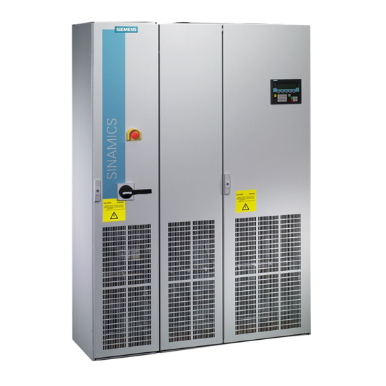
- Page 35 Device overview 2.3 Configuration Figure 2-2 Example of a cabinet unit (e.g., 200 HP, 3-phase 460 V AC) (configuration and components shown may vary by version) Enclosed Drives Operating Instructions, 12/2018, A5E36652151A...
-
Page 36: Wiring Principle
Device overview 2.4 Wiring principle Wiring principle Figure 2-3 Wiring principle of the cabinet unit Note PE connection of the motor The PE connection at the motor must be fed back directly to the cabinet unit. Enclosed Drives Operating Instructions, 12/2018, A5E36652151A... -
Page 37: Rating Plate
Device overview 2.5 Rating plate Rating plate Rating plate specifications Figure 2-4 Rating plate on the enclosed drive Enclosed Drives Operating Instructions, 12/2018, A5E36652151A... - Page 38 Device overview 2.5 Rating plate Rating plate specifications (from rating plate above) Table 2- 1 Rating plate specifications Item Specification Value Description ① Input 50/60HZ Line frequency 3-phase connection 380 ... 480 V Rated input voltage 242 A Rated input current ②...
-
Page 39: Date Of Manufacture
Device overview 2.5 Rating plate Date of manufacture The date of manufacture can be determined as follows: Table 2- 2 Production year and month Letter/number Year of manufacture Letter/number Month of manufacture 2010 1 ... 9 January to September 2011 October 2012 November... - Page 40 Device overview 2.5 Rating plate Explanation of the option codes Table 2- 3 Explanation of the option codes Enclosure Options Base (plinth), 4" (100 mm) high, RAL 9005 Cable marshalling compartment 8" (200 mm) high, RAL 7035 Line connection from above Enclosure NEMA 1 filtered Enclosure IP43 Enclosure NEMA 12 (ventilated) [derating, see Current derating as a function of the ambient temperature...
- Page 41 Device overview 2.5 Rating plate Additional TM31 customer terminal module TM31 wired to customer terminal block TM31 customer terminal block extension (G61) wired to customer terminal block SMC10 sensor module cabinet-mounted for speed or position measurement SMC20 sensor module cabinet-mounted for speed or position measurement SMC30 sensor module cabinet-mounted for speed measurement VSM10 sensor module cabinet-mounted CU320-2 PN control unit...
- Page 42 Device overview 2.5 Rating plate Enclosed Drives Operating Instructions, 12/2018, A5E36652151A...
-
Page 43: Mechanical Installation
Mechanical installation Chapter content This chapter provides information on the following: ● The conditions for transporting, storing, and installing the cabinet unit ● Preparing and installing the cabinet unit Transportation and storage Transport WARNING Incorrectly transporting the device The device can tip over if you transport it incorrectly or if you use non-approved transport equipment. - Page 44 • If you fail to contact the shipping company immediately, you may forfeit your right to claim compensation for the defects and damage. • If necessary, you can request the support of your local Siemens office. Storage The devices must be stored in clean, dry rooms. Temperatures between -13 °F (-25 °C) and 131 °F (+55 °C) are permissible.
-
Page 45: Installation
Mechanical installation 3.3 Installation Installation WARNING Failure to observe general safety instructions and residual risks If the general safety instructions and remaining risks are not observed, accidents can occur involving severe injuries or death. • Observe the general safety instructions. •... -
Page 46: Mechanical Installation: Checklist
Mechanical installation 3.3 Installation 3.3.1 Mechanical installation: checklist Use the following checklist to guide you through the mechanical installation procedure for the enclosed drive. Read the "Safety instructions" section at the start of these Operating Instructions before you start working on the device. Note Checking the checklist Check the first box in the column on the right if the action applies to your enclosed drive. -
Page 47: Requirements For Installation Location
Mechanical installation 3.3 Installation 3.3.2 Preparation 3.3.2.1 Requirements for installation location The enclosed drives are designed for installation in closed, electrical operating areas in compliance with IEC 61800-5-1. A closed electrical operating area is a room or area containing electrical equipment that can be accessed by trained personnel only. Access is controlled by a door or other form of barricade that can be opened only by means of a key or other tool. -
Page 48: Shipping And Handling Monitors
Mechanical installation 3.3 Installation Figure 3-1 Requirements on the levelness of the floor The following requirements must be met to ensure the full functionality of the cabinet units: ● The foundation must be level and horizontal. ● Irregularities must be leveled out. ①... - Page 49 Mechanical installation 3.3 Installation Figure 3-3 Shock indicator Position of the shipping and handling monitors The tilt indicators are affixed to the top of the cabinet unit inside the doors. The shock indicators are affixed to the bottom of the cabinet unit inside the doors. Checking the shipping and handling monitors prior to commissioning It is essential to check the shipping and handling monitors prior to commissioning the converter.
-
Page 50: Required Tools
Mechanical installation 3.3 Installation The shock indicator shows if an acceleration has exceeded 98.1 m/s (10 x g) and indicates the direction of acceleration. The black color of the arrows indicates that an impermissible shock load has occurred in the direction of the arrow. WARNING Damage to the device when shock or tilt indicators are tripped If a shock or tilt indicator has tripped, safe operation of the device cannot be guaranteed. - Page 51 Mechanical installation 3.3 Installation 3.3.3 Installation 3.3.3.1 Lifting the cabinet off the transport pallet Lifting the cabinet off the transport pallet The applicable local guidelines regarding the transportation of the cabinet from the transport palette to the installation location must be observed. A crane transport assembly (option M90) can also be fitted on the top of the cabinet.
-
Page 52: Removing The Crane Transport Aids
Mechanical installation 3.3 Installation Center of gravity of the cabinet The diagram below shows the center of gravity of the cabinet (for all sizes), which must always be taken into account when lifting and installing the cabinet. Figure 3-7 Center of gravity of the cabinet Note Center of gravity of the cabinet A label with the precise position of the center of gravity of the cabinet is attached to each... - Page 53 Mechanical installation 3.3 Installation Removal The transport eyebolts can be unscrewed and removed. Depending on the length of the cabinet or transport unit, the support rails can have a varying number of fastening screws. These must be unscrewed and removed before the rails can be removed. WARNING Incorrect handling of the mounting rails The improper handling of heavy carrying rails during disassembly can cause injuries or...
-
Page 54: Connection To The Foundation
Mechanical installation 3.3 Installation 3.3.3.3 Connection to the foundation Connection to the foundation Four holes for M12 screws are provided on each cabinet panel to secure the cabinet to the foundation. The fixing dimensions are specified in the dimension drawings. Every cabinet panel must be attached to the ground using at least two opposing attachment points (1 screw each in the front and rear part of the cabinet panel). -
Page 55: Line Connection From Above (Option M13), Motor Connection From Above (Option M78)
Mechanical installation 3.3 Installation 3.3.5 Line connection from above (option M13), motor connection from above (option M78) Description On options M13 and M78, the connection straps for the power cables, the clamping bar for mechanically securing the cables, an EMC shield bus, and a protective ground busbar are located within the tophat. - Page 56 Mechanical installation 3.3 Installation Figure 3-11 Attaching the tophat with M13 / M78 Enclosed Drives Operating Instructions, 12/2018, A5E36652151A...
-
Page 57: Electrical Installation
Electrical installation Chapter content This chapter provides information on the following: ● Establishing the electrical connections for the cabinet unit ● Adjusting the fan voltage and the internal power supply to local conditions (supply voltage) ● The customer terminal block and its interfaces ●... -
Page 58: Checklist For Electrical Installation
Electrical installation 4.2 Checklist for electrical installation Checklist for electrical installation Use the following checklist to guide you through the electrical installation procedure for the cabinet unit. Read the "Safety instructions" section at the start of these Operating Instructions before you start working on the device. Note Checking the checklist Check the first box in the column on the right if the action applies to your enclosed drive. - Page 59 Electrical installation 4.2 Checklist for electrical installation Item Action Completed A yellow warning label is attached to each connection clip for the basic interference suppression module. The warning label must be removed from the connection clip (by pulling it off) if •...
- Page 60 Electrical installation 4.2 Checklist for electrical installation Item Action Completed Option L50 The 115 V auxiliary supply for the cabinet light with an integrated service socket must be connected to terminal -X390 and Cabinet light protected with a fuse (max. 10 A) on the line end (see "Electrical with service installation/Other connections/Cabinet light with service socket socket...
- Page 61 Electrical installation 4.2 Checklist for electrical installation Item Action Completed Option K50 The SMC30 Sensor Module is used for acquiring the actual motor speed. Sensor Module Cabinet- The SMC30 Sensor Module supports the following: Mounted TTL encoder • SMC30 HTL encoder •...
- Page 62 Electrical installation 4.2 Checklist for electrical installation Item Action Completed Option L61/L62/ The connecting cables and ground for the braking resistor must L64/L65 be connected to terminal block –X5: 1/2. A connection must be made between the braking resistor thermostatic switch and 25 kW/125 kW customer terminal module –A65.
-
Page 63: Required Tool
Electrical installation 4.2 Checklist for electrical installation Required tool You require the following tools for the electrical installation: ● Standard set of tools with screwdrivers, screw wrenches, socket wrenches, etc. ● Torque wrench, 13 lb.in to 885 lb.in (1.5 Nm to 100 Nm) ●... -
Page 64: Important Safety Precautions
Electrical installation 4.3 Important safety precautions Important safety precautions WARNING Failure to observe general safety instructions and residual risks If the general safety instructions and remaining risks are not observed, accidents can occur involving severe injuries or death. • Observe the general safety instructions. •... -
Page 65: Introduction To Emc
Electrical installation 4.4 Introduction to EMC Introduction to EMC What is EMC? Electromagnetic compatibility (EMC) describes the capability of an electrical device to function satisfactorily in an electromagnetic environment without itself causing interference unacceptable for other devices in the environment. EMC therefore represents a quality feature for the ●... -
Page 66: Noise Emissions
Electrical installation 4.4 Introduction to EMC Noise emissions Product standard IEC 61800-3 describes the EMC requirements placed on "Variable-speed drive systems" (power drive systems). It specifies requirements for converters with operating voltages of less than 1000 V. Different environments and categories are defined depending on where the drive system is installed. -
Page 67: Emc-Compliant Design
Electrical installation 4.5 EMC-compliant design Table 4- 2 Definition of categories C1 to C4 Definition of categories C1 to C4 Category C1 Rated voltage < 1000 V; unrestricted use in the first environment. Category C2 Rated voltage for stationary drive systems < 1000 V; for use in the second environment. -
Page 68: Cable Installation
Electrical installation 4.5 EMC-compliant design Cable installation ● Cables that are subject to or sensitive to interference should be laid as far apart from each other as possible. ● All cables must be laid as close as possible to grounded enclosure parts such as mounting plates or cabinet frames. -
Page 69: Power Connections
Electrical installation 4.6 Power connections the clearance must be. If a sufficient clearance cannot be maintained, you must install additional shields. ● Avoid unnecessarily long cable loops. Filtering cables ● Line supply cables and power supply cables for devices and modules may have to be filtered in the cabinet to reduce incoming or outgoing disturbances. -
Page 70: Cable Lugs
Electrical installation 4.6 Power connections 4.6.1 Cable lugs Cable lugs The cable connections on the devices are designed for cable lugs according to DIN 46234 or DIN 46235. For connection of alternative cable lugs, the maximum dimensions are listed in the table below. -
Page 71: Connection Cross-Sections, Cable Lengths
Cable lengths The maximum permissible cable lengths are specified for standard cable types or cable types recommended by SIEMENS. Longer cables can only be used after consultation. The listed cable length represents the actual distance between the drive and the motor, taking into account factors such as parallel laying, current-carrying capacity, and the laying factor. - Page 72 Electrical installation 4.6 Power connections 4.6.3 Connecting shielded three-phase current cables A good shield connection is achieved by connecting the shields in the converter cabinet through a large surface area to the EMC shield rail using EMC shield clamps (PUK shield clamps).
- Page 73 Electrical installation 4.6 Power connections Cabinet units 380 ... 480 V: 150 HP (110 kW) ... 600 HP (400 kW). 500 ... 690 V: 75 HP (75 kW) ... 600 HP (560 kW) Connect the power cable according to the numbers in the following diagram. Figure 4-5 Power cable connection Enclosed Drives...
- Page 74 Electrical installation 4.6 Power connections 1. Open the cabinet, remove any covers in front of the terminals for the motor cables (connections U2/T1, V2/T2, W2/T3; X2) and power cables (connections U1/L1, V1/L2, W1/L3; X1). Remove or move the base plate under the terminals for inserting the power or motor cables.
-
Page 75: Direction Of Motor Rotation
Electrical installation 4.6 Power connections NOTICE Property damage due to loose power connections Insufficient tightening torques or vibrations can result in faulty electrical connections. This can cause fire damage or malfunctions. • Tighten all power connections with the specified tightening torques, e.g. power connection, motor connection, and DC link connections. - Page 76 Electrical installation 4.6 Power connections Note Information on the phase sequence If an incorrect phase sequence was connected when the motor was connected, p1821 (phase sequence direction reversal) can be used to correct the incorrect phase sequence without physically changing it over (see "Functions, monitoring and protective functions/ direction reversal").
- Page 77 Electrical installation 4.6 Power connections Figure 4-6 Setting terminals for the fan transformers (380 to 480 V 3 AC / 500 to 690 V 3 AC) The line voltage assignments for making the appropriate setting on the fan transformer are indicated in the following tables.
- Page 78 Electrical installation 4.6 Power connections Table 4- 6 Line voltage assignment for the setting at the fan transformer (3-phase 500 ... 690 V AC) Line voltage Taps of the fan transformer (-G1-T10, -T1-T10) 500 V ± 10% 500 V 525 V ± 10% 525 V 575 V ±...
- Page 79 Electrical installation 4.6 Power connections Table 4- 8 Line voltage assignments for the internal power supply (3 AC 500 ... 690 V) Line voltage range Adaptation transformer taps (-T10) LH1 – LH2 450 ... 515 V 500 V 1 - 8 516 ...
- Page 80 Electrical installation 4.6 Power connections Figure 4-8 Removing the connection bracket to the basic interference suppression module in the Active Interface Module for frame size FI Enclosed Drives Operating Instructions, 12/2018, A5E36652151A...
- Page 81 Electrical installation 4.6 Power connections Figure 4-9 Removing the connection bracket to the basic interference suppression module in the Active Interface Module for frame size GI Enclosed Drives Operating Instructions, 12/2018, A5E36652151A...
- Page 82 Electrical installation 4.6 Power connections Figure 4-10 Removing the connecting clip to the basic interference suppression module in the Active Interface Module for frame size HI Enclosed Drives Operating Instructions, 12/2018, A5E36652151A...
- Page 83 Electrical installation 4.6 Power connections Figure 4-11 Removing the connecting clip to the basic interference suppression module in the Active Interface Module for frame size JI Enclosed Drives Operating Instructions, 12/2018, A5E36652151A...
- Page 84 Electrical installation 4.6 Power connections Removing the connector jumper in the VSM10 Voltage Sensing Module When operating the cabinet unit on an ungrounded line supply (IT system), at the Voltage Sensing Module (VSM10), remove the plug-in jumper in terminal X530 at the lower side of the component.
- Page 85 Electrical installation 4.6 Power connections Connecting Table 4- 9 Terminal block X50 – "Circuit breaker closed" checkback contact Terminal Designation Technical data Max. load current: 10 A Max. switching voltage: 250 V AC Max. contact rating: 250 VA Required minimum load: ≥ 1 mA Max.
- Page 86 Electrical installation 4.7 External supply of the auxiliary incoming supply from a protected supply system WARNING Incorrect circuit breaker setting An incorrect setting can cause unwanted or delayed tripping of the circuit breaker and result in damage to the cabinet unit and can therefore result in death or severe injury. •...
- Page 87 Electrical installation 4.8 Signal connections 4.7.1 115 V AC auxiliary incoming supply The fuse must not exceed 16 A. The connection is protected inside the cabinet with a 10 A fuse. Connection ● On terminal block -X40, remove the jumpers between terminals 1 and 2 as well as 5 and 6.
-
Page 88: Connection Overview
Electrical installation 4.8 Signal connections Connection overview Figure 4-12 Connection overview of the CU320-2 DP Control Unit (without cover) Enclosed Drives Operating Instructions, 12/2018, A5E36652151A... - Page 89 Electrical installation 4.8 Signal connections Figure 4-13 Interface X140 and measuring sockets T0 to T2 - CU320-2 DP (view from below) NOTICE Malfunctions or damage to the option board by inserting and withdrawing in operation Withdrawing and inserting the option board in operation can damage it or cause it to malfunction.
-
Page 90: Connection Example
Electrical installation 4.8 Signal connections Connection example Figure 4-14 Connection example of CU320-2 DP Enclosed Drives Operating Instructions, 12/2018, A5E36652151A... - Page 91 Electrical installation 4.8 Signal connections X100 to X103: DRIVE-CLiQ interface Table 4- 11 DRIVE-CLiQ interface X100 – X103 Connector Signal name Technical data Transmit data + Transmit data - Receive data + Reserved, do not use Reserved, do not use Receive data - Reserved, do not use Reserved, do not use...
-
Page 92: Electrical Installation
Electrical installation 4.8 Signal connections X122: Digital inputs/outputs Table 4- 12 Terminal block X122 Designation Technical specifications DI 0 Voltage (max.): -3 ... +30 V DC Typical power consumption: 9 mA at 24 V DI 1 Electrical isolation: reference potential is terminal M1 DI 2 Signal level (with ripple) DI 3... - Page 93 Electrical installation 4.8 Signal connections Note Ensuring the function of digital inputs An open input is interpreted as "low". Terminal M1 must be connected so that the digital inputs (DI) can function. This is achieved through one of the following measures: 1.
-
Page 94: X132: Digital Inputs/Outputs
Electrical installation 4.8 Signal connections X132: Digital inputs/outputs Table 4- 13 Terminal block X132 Designation Technical specifications DI 4 Voltage (max.): -3 ... +30 V DC Current consumption, typical: 9 mA at 24 V DI 5 Electrical isolation: reference potential is terminal M2 DI 6 Level (including ripple) DI 7... - Page 95 Electrical installation 4.8 Signal connections Note Ensuring the function of digital inputs An open input is interpreted as "low". To enable the digital inputs (DI) to function, terminal M2 must be connected. This is achieved through one of the following measures: 1.
- Page 96 Electrical installation 4.8 Signal connections X126: PROFIBUS connection The PROFIBUS is connected by means of a 9-pin SUB D socket (X126). The connections are electrically isolated. Table 4- 14 PROFIBUS interface X126 Connector Signal name Meaning Range Not assigned M24_SERV Power supply for teleservice, ground RxD/TxD–P Receive/transmit data P (B)
-
Page 97: Bus Terminating Resistor
Electrical installation 4.8 Signal connections Connectors The cables must be connected via PROFIBUS connectors as they contain the necessary terminating resistors. The figure below shows suitable PROFIBUS connectors with/without a PG/PC connector. PROFIBUS connector PROFIBUS connector without PG/PC connection with PG/PC connection 6ES7972-0BA42-0XA0 6ES7972-0BB42-0XA0 Bus terminating resistor... -
Page 98: Profibus Address Switches
Electrical installation 4.8 Signal connections Figure 4-15 Position of the bus terminating resistors PROFIBUS address switches The PROFIBUS address is set as a hexadecimal value via two rotary coding switches. Values between 0 ) and 127 ) can be set as the address. The upper rotary coding switch (H) is used to set the hexadecimal value for 16 and the lower rotary coding switch (L) is used to set the hexadecimal value for 16... -
Page 99: X127: Lan (Ethernet)
Electrical installation 4.8 Signal connections Note The rotary coding switches used to set the PROFIBUS address are located beneath the cover. Note Address 126 is used for commissioning. Permitted PROFIBUS addresses are 1 ... 126. When several Control Units are connected to a PROFIBUS line, you set the addresses differently than for the factory setting. - Page 100 Electrical installation 4.8 Signal connections Table 4- 16 X127 LAN (Ethernet) Connector Designation Technical data Ethernet transmit data + Ethernet transmit data - Ethernet receive data + Reserved, do not use Reserved, do not use Ethernet receive data - Reserved, do not use Reserved, do not use Connector type: RJ45 socket Note...
- Page 101 Electrical installation 4.8 Signal connections X140: Serial interface (RS232) The AOP30 operator panel for operating/parameterizing the device can be connected via the serial interface. The interface is located on the underside of the Control Unit. Table 4- 18 Serial interface (RS232) X140 Connector Designation Technical data...
-
Page 102: Diag Button
Electrical installation 4.8 Signal connections Note Using the measuring socket contacts The measuring socket contacts support commissioning and diagnostic functions. It must not be connected for normal operation. DIAG button The DIAG pushbutton is reserved for service functions. Slot for the memory card Figure 4-16 Slot for the memory card Enclosed Drives... - Page 103 • Do not return the memory card as well, but rather keep it in a safe place so that it can be inserted in the replacement unit. Note Please note that only SIEMENS memory cards can be used to operate the Control Unit. Enclosed Drives Operating Instructions, 12/2018, A5E36652151A...
-
Page 104: Customer Terminal Block
Electrical installation 4.8 Signal connections 4.8.2 Customer terminal block 4.8.2.1 Customer interface / shield connection Note Preassignment and position of the customer terminal block The factory setting and description of the customer terminal module can be found in the circuit diagrams. The location of the customer terminal module in the enclosed drive is indicated in the layout diagram. - Page 105 Electrical installation 4.8 Signal connections Figure 4-17 Shield connection Enclosed Drives Operating Instructions, 12/2018, A5E36652151A...
-
Page 106: Customer Terminal Block (-A60)
Electrical installation 4.8 Signal connections 4.8.2.2 Customer terminal block (-A60) Overview Figure 4-18 TM31 customer terminal block Enclosed Drives Operating Instructions, 12/2018, A5E36652151A... - Page 107 Electrical installation 4.8 Signal connections Figure 4-19 Connection overview of TM31 customer terminal block Enclosed Drives Operating Instructions, 12/2018, A5E36652151A...
- Page 108 Electrical installation 4.8 Signal connections 4.8.2.3 Customer terminal block (-X65) (with option G65) Overview Figure 4-20 Customer terminal module Enclosed Drives Operating Instructions, 12/2018, A5E36652151A...
- Page 109 Electrical installation 4.8 Signal connections Figure 4-21 Connection overview of customer terminal module Enclosed Drives Operating Instructions, 12/2018, A5E36652151A...
-
Page 110: Terminal Descriptions
Electrical installation 4.8 Signal connections 4.8.2.4 Terminal descriptions X520: 4 digital inputs Table 4- 20 Terminal block X520 Connector Terminal Designation Technical specifications DI 0 Voltage: - 3 … +30 V Current consumption typical: 10 mA at 24 V DC DI 1 Input delay: DI 2... - Page 111 Electrical installation 4.8 Signal connections X530: 4 digital inputs Table 4- 21 Terminal block X530 Connector Terminal Designation Technical specifications DI 4 Voltage: - 3 … +30 V Current consumption typical: 10 mA at 24 V DC DI 5 Input delay: DI 6 For "0"...
- Page 112 Electrical installation 4.8 Signal connections X521: 2 analog inputs (differential inputs) Table 4- 22 Terminal block X521 Connector Terminal Designation Technical specifications AI 0+ The analog inputs can be toggled between current and voltage input using switches S5.0 and S5.1. AI 0- As voltage input: AI 1+...
- Page 113 Electrical installation 4.8 Signal connections S5: Selector for voltage/current AI0, AI1 Note Position of the selector The selector is located on the customer terminal block TM31 (-A60), a selector setting also has to be made on TM31 for devices with option G65. Table 4- 23 Selector for voltage/current S5 Switch...
- Page 114 Electrical installation 4.8 Signal connections WARNING Electric shock in the event of voltage flashovers at the temperature sensor Voltage flashovers in the signal electronics can occur in motors without safe electrical separation of the temperature sensors. • Use temperature sensors that fully comply with the specifications of the safety isolation. NOTICE Damage or malfunction due to impermissible voltage values If the back EMF is impermissible, the components may be damaged or malfunction.
- Page 115 Electrical installation 4.8 Signal connections X541: 4 non-floating digital inputs/outputs Table 4- 26 Terminal strip X541 Connector Terminal Designation Technical specifications Auxiliary voltage: Voltage: +24 V DC DI/DO 11 Max. total load current of +24 V auxiliary voltage for DI/DO 10 terminals X540 and X541 combined: 150 mA DI/DO 9 As input:...
-
Page 116: Additional Connections
Electrical installation 4.9 Additional connections X542: 2 relay outputs (two-way contact) Table 4- 27 Terminal block X542 Connector Terminal Designation Technical specifications DO 0.NC Contact type: Change-over contact max. load current: 8 A Max. switching voltage: 250 V . 30 V DO 0.COM Max. - Page 117 Electrical installation 4.9 Additional connections 4.9.1 Infeed module rated one level lower (option L04) Description With this option, an infeed (Active Line Module / Active Interface Module) rated one power level lower than the Motor Module (inverter) is used. The option is suitable for the following applications, for example: ●...
- Page 118 Electrical installation 4.9 Additional connections Note Shutdown in the event of an overload If these restrictions are not heeded, a fault trip may occur in the event of an overload (of the infeed). To remedy this, adapt the current and/or torque limits in the Motor Module to match the infeed.
-
Page 119: Electrical Installation
Electrical installation 4.9 Additional connections Technical data The technical data of the cabinet units are different when Option L04 is present. Table 4- 28 Version with option L04, 3-phase 380 ... 480 V AC, part 1 Article no. 6SL3710- 7LE33-1AU3 7LE35-0AU3 7LE36-1AU3 Unit rating... - Page 120 Electrical installation 4.9 Additional connections Article no. 6SL3710- 7LE33-1AU3 7LE35-0AU3 7LE36-1AU3 Fuse type per phase 3NE1331-2 3NE1334-2 3NE1436-2 Rated current Frame size acc. to IEC 60269 UL file no. E167357 SCCR (short circuit current rating) according to UL508A File no. E83449 Minimum short-circuit current 3000...
- Page 121 Electrical installation 4.9 Additional connections Table 4- 29 Version with option L04, 3-phase 380 ... 480 V AC, part 2 Article no. 6SL3710- 7LE37-5AU3 7LE41-0AU3 Unit rating - for I at 50 Hz 400 V - for I at 50 Hz 400 V - for I at 60 Hz 460 V - for I...
-
Page 122: Dv/Dt Filter Plus Voltage Peak Limiter (Option L10)
Electrical installation 4.9 Additional connections Article no. 6SL3710- 7LE37-5AU3 7LE41-0AU3 SCCR (short circuit current rating) according to UL508A File no. E83449 Minimum short-circuit current 12000 2500 Rated output of a typical 6-pole standard induction motor based on I or I at 400 V 3 AC 50 Hz. - Page 123 Electrical installation 4.9 Additional connections Table 4- 30 Accommodating the voltage limiting network in the cabinet or in an additional cabinet Voltage range Installation of the dv/dt filter Installation of the voltage Installation of the voltage plus Voltage Peak Limiter limiting network in an additional limiting network in an additional within the converter cabinet...
- Page 124 Electrical installation 4.9 Additional connections NOTICE Damage to the dv/dt filter if it is not activated during commissioning The dv/dt filter may be damaged if it is not activated during commissioning. • Activate the dv/dt filter during commissioning using parameter p0230 = 2. NOTICE Damage to the dv/dt filter if a motor is not connected dv/dt filters which are operated without a motor being connected can be damaged or...
- Page 125 Electrical installation 4.9 Additional connections Table 4- 32 Max. pulse frequency when a dv/dt filter plus Voltage Peak Limiter is used in units with a rated pulse frequency of 1.25 kHz Article no. Unit rating Output current for a pulse Max.
- Page 126 Electrical installation 4.9 Additional connections 4.9.3 Feeder for external auxiliaries / motor blower (option L17) Description This option includes a switched outgoing feeder with 3-phase AC line voltage and max. 10 A fuse protection for an external auxiliary device /motor fan. The voltage is tapped at the converter input upstream of the main contactor/circuit breaker and, therefore, has the same level as the supply voltage.
- Page 127 Electrical installation 4.9 Additional connections Circuit proposal for controlling the auxiliary contactor from within the drive The following circuit, for example, can be used if the auxiliary contactor is to be controlled from within the drive. The “Operation” message is then no longer available for other purposes.
- Page 128 As a consequence, sensitive devices that are connected to the same line connection point could be damaged. Contact the Siemens AG hotline within the next 4 weeks. 4.9.5 Enclosure light with service socket (option L50)
- Page 129 Electrical installation 4.9 Additional connections Connecting Table 4- 34 Terminal block X390 – connection for enclosure light with service socket Terminal Designation Technical specifications 115 V AC Power supply Protective ground Protective conductor Max. connectable cross-section: #12 AWG (4 mm²) 4.9.6 Enclosure space heater (option L55) Description...
- Page 130 Electrical installation 4.9 Additional connections Connecting Table 4- 35 Terminal block X240 – connection for enclosure space heater Terminal Designation Technical specifications 115 V AC Power supply Protective ground Protective conductor Max. connectable cross-section: #12 AWG (4 mm²) 4.9.7 ALL STOP, coast to stop (option N55) Description The mushroom pushbutton with protective collar and interlock is mounted in the door of the enclosed drive and its contacts are wired to the OFF2 terminal of the Control Unit.
- Page 131 Electrical installation 4.9 Additional connections Connecting Table 4- 36 Terminal block X120 – Connection for EMERGENCY OFF category 0, 115 V AC and 24 V DC Terminal 115 V AC and 24 V DC button circuit Jumper wired at the factory Loop in EMERGENCY OFF button from line side: Remove jumpers 7-8 and connect button: Jumper wired at the factory...
- Page 132 Electrical installation 4.9 Additional connections 4.9.9 EMERGENCY STOP category 1; 115 V AC (option N59) Description EMERGENCY OFF category 1 for controlled stop according to IEC 60204-1. The function includes the stopping of the drive via an emergency stop according to an assigned ramp- down.
-
Page 133: Emergency Stop Category 1; 24 V Dc (Option L60)
Electrical installation 4.9 Additional connections 4.9.10 EMERGENCY STOP category 1; 24 V DC (option L60) Description EMERGENCY OFF category 1 for controlled stop according to IEC 60204-1. The function includes the stopping of the drive via an emergency stop according to an assigned ramp- down. -
Page 134: Installing The Braking Resistor
Electrical installation 4.9 Additional connections 4.9.11 25 kW braking unit (option L61/L64); 50 kW braking unit (option L62/L65) Description Under normal circumstances, the braking energy is supplied back to the line. If a controlled stop is also required in the event of a power failure, however, additional braking units can be provided. - Page 135 Electrical installation 4.9 Additional connections WARNING Fire as a result of inadequate installation When installation is inadequate (failure to observe the cooling clearances or insufficient distances from combustible objects), there is a risk of fire leading to death or serious injury. •...
-
Page 136: Connecting The Braking Resistor
Electrical installation 4.9 Additional connections Figure 4-24 Dimension drawing of braking resistor rated 50 kW - Specifications in inches (mm) Connecting the braking resistor WARNING Fire caused by ground fault / short-circuit for non-protected connections to the braking resistor Non-fused connections to the braking resistor can cause fire with smoke generation in the event of a short-circuit or ground fault and cause serious injuries or death. - Page 137 Electrical installation 4.9 Additional connections NOTICE Material damage when exceeding the maximum permitted cable length Exceeding the maximum permitted cable length to the braking resistor can cause property damage due to component failure. • Comply with the maximum cable length between the cabinet unit and the braking resistor of 330 ft (100 m).
- Page 138 Electrical installation 4.9 Additional connections 4.9.11.2 Commissioning Commissioning When commissioning via STARTER, parameters are assigned to "external fault 3" and acknowledged automatically when option L61, L62, L64, or L65 is selected. When commissioning via AOP30, the parameter entries required have to be set subsequently.
-
Page 139: Diagnosis And Duty Cycles
Electrical installation 4.9 Additional connections 4.9.11.3 Diagnosis and duty cycles Diagnosis If the thermostat is opened due to a thermal overload on the braking resistor, fault F7861 ("External Fault 2") is triggered and the drive is switched off with OFF2. If the brake chopper triggers a fault, fault F7862 "External fault 3"... -
Page 140: Electrical Installation
Electrical installation 4.9 Additional connections WARNING Electric shock when operating the threshold switch Operating the threshold switch when a voltage is present can cause death or serious injury. • Only operate the threshold switch when the cabinet unit is switched off and the DC link capacitors are discharged. - Page 141 Electrical installation 4.9 Additional connections Position of the threshold switch The braking module is located in the exhaust air duct of the Power Module at the top of the cabinet unit. The position of the threshold switch is indicated in the figures below. Figure 4-26 Braking modules for frame size FX Enclosed Drives...
- Page 142 Electrical installation 4.9 Additional connections Figure 4-27 Braking modules for frame size GX Enclosed Drives Operating Instructions, 12/2018, A5E36652151A...
- Page 143 Electrical installation 4.9 Additional connections Figure 4-28 Braking modules for frame sizes HX and JX Position of the threshold switch Note Switch positions The threshold switches for the braking modules are positioned on the panel as follows: • Braking modules for frame sizes FX and GX: Position "1" is up; position "2" is down •...
-
Page 144: Insulation Monitor (Option L87)
4.9.12 Line-side surge arrester (option L96) Description The Siemens TPS3-03 surge arrester protects the cabinet components from overvoltages. The device is connected after the mains switch. A green LED on the device (equipment designation -A96) indicates the correct functioning. If this LED is dark when voltage is applied, the device must be replaced. - Page 145 Electrical installation 4.9 Additional connections Controls and displays on the insulation monitor Figure 4-29 Controls and displays on the insulation monitor Table 4- 44 Meaning of the controls and displays on the insulation monitor Position Meaning INFO key: Requests standard information/ ESC key: Back menu function TEST key: Brings up self-test Arrow key up: Parameter change, scroll function...
- Page 146 Electrical installation 4.9 Additional connections Connecting Table 4- 45 Connections on the insulation monitor Terminal Technical specifications Supply voltage via 6 A melting fuse: 88 to 264 V AC, 77 to 286 V DC Connection of the 3 ph. AC system to be monitored Connection to coupling device Connection to protective ground External test button...
- Page 147 Electrical installation 4.9 Additional connections Adapting the auxiliary power supply (-T10) A transformer is installed in the Line Connection Module (-T10) to produce the auxiliary voltages of the enclosed drive. The location of the transformer is indicated in the layout diagrams supplied.
-
Page 148: Cbc10 Can Communication Board (Option G20)
Electrical installation 4.9 Additional connections 4.9.15 CBC10 CAN Communication Board (option G20) Description Figure 4-30 CAN CBC10 Communication Board The CBC10 CANopen communication board (CAN Communication Board) is used to connect drives in the SINAMICS drive system to higher-level automation systems with a CAN bus. -
Page 149: Interface Overview
Electrical installation 4.9 Additional connections Interface overview Figure 4-31 CAN CBC10 Communication Board Enclosed Drives Operating Instructions, 12/2018, A5E36652151A... - Page 150 Electrical installation 4.9 Additional connections CAN bus interface -X451 Table 4- 48 CAN bus interface -X451 Connector Designation Technical data Reserved, do not use CAN_L CAN signal (dominant low) CAN_GND CAN ground Reserved, do not use CAN_SHLD Optional shield CAN ground CAN_H CAN signal Reserved, do not use...
-
Page 151: Communication Board Ethernet Cbe20 (Option G33)
Electrical installation 4.9 Additional connections Further information about communication via CAN bus Note Further information Detailed and comprehensive instructions and information for the CANopen interface can be found in the accompanying Function Manual. This manual is available as additional documentation on the accompanying customer DVD. 4.9.16 Communication Board Ethernet CBE20 (option G33) Description... -
Page 152: Mac Address
Electrical installation 4.9 Additional connections Interface overview Figure 4-33 Communication Board Ethernet CBE20 MAC address The MAC address of the Ethernet interfaces is indicated on the upper side of the CBE20. The plate is not visible when the module is installed. Note Note the MAC address Remove the module from the option slot of the Control Unit and note down the MAC address... -
Page 153: X1400 Ethernet Interface
Electrical installation 4.9 Additional connections Figure 4-34 Removing the CBE20 from the option slot on the Control Unit X1400 Ethernet interface Table 4- 50 Connector X1400, port 1 - 4 Connector Signal name Technical data Receive data + Receive data - Transmit data + Reserved, do not use Reserved, do not use... - Page 154 Electrical installation 4.9 Additional connections 4.9.17 TM150 Temperature Sensor Module (option G51, G52) 4.9.17.1 Description Terminal Module TM150 is used for sensing and evaluating several temperature sensors. The temperature is measured in a temperature range from -99 °C to +250 °C for the following temperature sensors: ●...
-
Page 155: Temperature Sensor Connections
Electrical installation 4.9 Additional connections 4.9.17.2 Connecting Temperature sensor connections Table 4- 51 X531-X536 temperature sensor inputs Connector Terminal Function Function Technical specifications 1x2- / 2x2-wire 3- and 4-wire +Temp Temperature sensor connection for sensors with (channel x) (Channel x) 1x2 wires Connection of the 2nd measurement cable for sensors with 4 wires... - Page 156 Electrical installation 4.9 Additional connections WARNING Electric shock in the event of voltage flashovers at the temperature sensor Voltage flashovers in the signal electronics can occur in motors without safe electrical separation of the temperature sensors. • Use temperature sensors that fully comply with the specifications of the safety isolation. NOTICE Damage to motor when KTY temperature sensor is connected incorrectly If a KTY temperature sensor is connected with incorrect polarity, it is not possible to detect...
- Page 157 Electrical installation 4.9 Additional connections Protective earth connection and shield support The following diagram shows a typical Weidmüller shield connection clamp for the shield supports. ① Protective earth connection M4/1.8 Nm ② Shield connection terminal, Weidmüller company, type: KLBÜ CO1, order number: 1753311001 Figure 4-36 Shield support and protective earth connection of the TM150...
-
Page 158: Connection Examples
Electrical installation 4.9 Additional connections 4.9.17.3 Connection examples Figure 4-37 Connecting a PT100/PT1000 with 2x2, 3 and 4-wires to the temperature sensor inputs X53x of Terminal Module TM150 Enclosed Drives Operating Instructions, 12/2018, A5E36652151A... - Page 159 Electrical installation 4.9 Additional connections Figure 4-38 Connection example for a Terminal Module TM150 Enclosed Drives Operating Instructions, 12/2018, A5E36652151A...
- Page 160 Electrical installation 4.9 Additional connections 4.9.18 SMC10 Sensor Module Cabinet-Mounted (option K46) 4.9.18.1 Description The SMC10 Sensor Module is used for determining the actual motor speed and the rotor position angle. The signals received from the resolver are converted here and made available to the closed-loop controller via the DRIVE-CLiQ interface for evaluation purposes.
- Page 161 Electrical installation 4.9 Additional connections 4.9.18.2 Connection X520: Encoder connection Table 4- 53 Encoder connection X520 Connector Signal name Technical data Reserved, do not use Reserved, do not use Resolver signal A (sin+) Inverted resolver signal A (sin-) Ground Ground (for internal shield) Resolver signal B (cos+) Inverted resolver signal B (cos-) Ground...
- Page 162 Electrical installation 4.9 Additional connections WARNING Electric shock in the event of voltage flashovers at the temperature sensor Voltage flashovers in the signal electronics can occur in motors without safe electrical separation of the temperature sensors. • Only use temperature sensors that fully comply with the specifications of the safety isolation.
- Page 163 Electrical installation 4.9 Additional connections 4.9.18.3 Connection example Connection example: Resolver, 8-pin Figure 4-40 Connection example: Resolver, 8-pin Enclosed Drives Operating Instructions, 12/2018, A5E36652151A...
-
Page 164: Parameter Settings
Electrical installation 4.9 Additional connections Parameter settings Table 4- 54 Parameter settings for an 8-pole resolver at the SMC10 Parameter Name Value p0400[0] Enc type selection Resolver 4 speed (1004) p0404[0] Encoder configuration effective 800010(hex) p0404[0].0 Linear encoder p0404[0].1 Absolute encoder p0404[0].2 Multiturn encoder p0404[0].3... - Page 165 Electrical installation 4.9 Additional connections 4.9.19 SMC20 Sensor Module Cabinet-Mounted (option K48) 4.9.19.1 Description Description The SMC20 Sensor Module is used for determining the actual motor speed and the path length. The signals emitted by the rotary pulse encoder are converted here and made available to the closed-loop controller via the DRIVE-CLiQ interface for evaluation purposes.
- Page 166 Electrical installation 4.9 Additional connections 4.9.19.2 Connection X520: Encoder connection Table 4- 55 Encoder connection X520 Connector Signal name Technical data P encoder Encoder supply M encoder Ground for encoder power supply Incremental signal A Inverse incremental signal A Ground Ground (for internal shield) Incremental signal B Inverse incremental signal B...
- Page 167 Electrical installation 4.9 Additional connections WARNING Electric shock in the event of voltage flashovers at the temperature sensor Voltage flashovers in the signal electronics can occur in motors without safe electrical separation of the temperature sensors. • Only use temperature sensors that fully comply with the specifications of the safety isolation.
-
Page 168: Connection Example
Electrical installation 4.9 Additional connections 4.9.19.3 Connection example Connection example: Incremental encoder sin/cos 1 Vpp, 2048 Figure 4-42 Connection example: Incremental encoder sin/cos 1 Vpp, 2048 Enclosed Drives Operating Instructions, 12/2018, A5E36652151A... - Page 169 Electrical installation 4.9 Additional connections Parameter settings Table 4- 56 Parameter settings for incremental encoder sin/cos on SMC20 Parameter Name Value p0400[0] Enc type selection 2048, 1 Vpp, A/B R (2002) p0404[0] Encoder configuration effective 101010(hex) p0404[0].0 Linear encoder p0404[0].1 Absolute encoder p0404[0].2 Multiturn encoder...
-
Page 170: Smc30 Sensor Module Cabinet-Mounted (Option K50)
Electrical installation 4.9 Additional connections 4.9.20 SMC30 Sensor Module Cabinet-Mounted (option K50) 4.9.20.1 Description The SMC30 Sensor Module is used for acquiring the actual motor speed. The signals emitted by the rotary pulse encoder are converted here and made available to the closed- loop controller via the DRIVE-CLiQ interface for evaluation purposes. - Page 171 Electrical installation 4.9 Additional connections Table 4- 59 Specification of measuring systems that can be connected Parameter Designation Threshold Min. Max. Unit High signal level Hdiff (TTL bipolar at X520 or X521/X531) Low signal level Ldiff (TTL bipolar to X520 or X521/X531) High signal level High (HTL unipolar)
- Page 172 Electrical installation 4.9 Additional connections Figure 4-44 Position of the zero pulse to the track signals For encoders with a 5 V supply at X521/X531, the cable length is dependent on the encoder current (this applies to cable cross-sections of 0.5 mm²): Figure 4-45 Signal cable length as a function of the encoder current consumption For encoders without Remote Sense, the permissible cable length is restricted to 330 ft...
- Page 173 Electrical installation 4.9 Additional connections Figure 4-46 SMC30 Sensor Module Enclosed Drives Operating Instructions, 12/2018, A5E36652151A...
- Page 174 Electrical installation 4.9 Additional connections 4.9.20.2 Connection X520: Encoder connection 1 for HTL/TTL/SSI encoder with open-circuit monitoring Table 4- 60 Encoder connection X520 Connector Signal name Technical data Temperature sensor connection +Temp KTY84-1C130 / PT1000 / PTC Clock SSI clock Clock* Inverse SSI clock P encoder 5 V/24 V...
- Page 175 Electrical installation 4.9 Additional connections WARNING Electric shock in the event of voltage flashovers at the temperature sensor Voltage flashovers in the signal electronics can occur in motors without safe electrical separation of the temperature sensors. • Only use temperature sensors that fully comply with the specifications of the safety isolation.
- Page 176 Electrical installation 4.9 Additional connections X521 / X531: Encoder connection 2 for HTL/TTL/SSI encoder with open-circuit monitoring Table 4- 61 Encoder connection X521 Connector Terminal Signal name Technical data Incremental signal A Inverse incremental signal A Incremental signal B Inverse incremental signal B Reference signal R Inverse reference signal R CTRL...
- Page 177 Electrical installation 4.9 Additional connections WARNING Electric shock in the event of voltage flashovers at the temperature sensor Voltage flashovers in the signal electronics can occur in motors without safe electrical separation of the temperature sensors. • Only use temperature sensors that fully comply with the specifications of the safety isolation.
- Page 178 Electrical installation 4.9 Additional connections 4.9.20.3 Connection examples Connection example 1: HTL encoder, bipolar, without zero marker -> p0405 = 9 (hex) Figure 4-47 Connection example 1: HTL encoder, bipolar, without zero marker Connection example 2: TTL encoder, unipolar, without zero marker -> p0405 = A (hex) Figure 4-48 Connection example 2: TTL encoder, unipolar, without zero marker Enclosed Drives...
-
Page 179: Voltage Sensing Module For Determining The Actual Motor Speed And The Phase Angle (Option K51)
Electrical installation 4.9 Additional connections 4.9.21 Voltage Sensing Module for determining the actual motor speed and the phase angle (option K51) Description The VSM10 Voltage Sensing Module is used for acquiring the voltage characteristic on the motor side, so that the following functions can be implemented: ●... -
Page 180: Additional Customer Terminal Block Tm31 (Option G61)
Electrical installation 4.9 Additional connections 4.9.22 Additional SMC30 Sensor Module (option K52) Description With option K50, an SMC30 Sensor Module is included in the cabinet unit. The additional SMC30 Sensor Module enables reliable actual value acquisition when using Safety Integrated Extended Functions (requires a license: option K01). Note Safety Integrated Function Manual A detailed description of the full functionality and handling of the Safety Integrated functions... - Page 181 With option K01, the Safety license for 1 axis is included on the CompactFlash Card and activated. Licenses The required license can optionally be ordered with the CompactFlash card. Subsequent licensing is realized in the Internet using the "WEB License Manager" by generating a license key: http://www.siemens.com/automation/license Enclosed Drives Operating Instructions, 12/2018, A5E36652151A...
-
Page 182: Terminal Module For Activation Of "Safe Torque Off" And "Safe Stop 1" (Option K82)
Electrical installation 4.9 Additional connections Activation The associated license key is entered into parameter p9920 in the ASCII code. The license key is activated using parameter p9921 = 1. Diagnostics An insufficient license is indicated via the following alarm and LED: ●... - Page 183 Electrical installation 4.9 Additional connections Note Safety Integrated Function Manual Detailed and comprehensive instructions and information for the Safety Integrated functions can be found in the accompanying Function Manual. This manual is available as additional documentation on the customer DVD supplied with the device. 4.9.28 Terminal Module TM54F (option K87) Figure 4-49...
- Page 184 Electrical installation 4.9 Additional connections TM54F features the following interfaces: Table 4- 63 Overview of the TM54F interfaces Type Quantity Fail-safe digital outputs (F-DO) Fail-safe digital inputs (F-DI) Sensor power supplies, dynamic response supported Sensor power supply, no dynamic response Digital inputs to check F_DO for a test stop Sensors: Fail-safe devices to issue commands and sense, for example, emergency stop pushbuttons and safety locks, position switches and light arrays/light curtains.
-
Page 185: Safe Brake Adapter Sba 230 V Ac (Option K88)
Electrical installation 4.9 Additional connections 4.9.29 Safe Brake Adapter SBA 230 V AC (option K88) Description Safe Brake Control (SBC) is a safety function that is used in safety-related applications. In the no-current state, the brake acts on the motor of the drive using spring force. The brake is released (opened) when current flows through it (= low active). -
Page 186: Control Unit Cu320-2 Pn (Option K95)
Electrical installation 4.9 Additional connections Notes Note Replacement fuses The article numbers for spare fuses can be taken from the spare parts list supplied. Note Standards requirements The integrated safety functions, starting from the Safety Integrated (SI) input terminals of the SINAMICS components (Control Unit, Motor Module), satisfy the requirements according to EN 61800-5-2, EN 60204-1, EN ISO 13849-1 Category 3 (formerly EN 954-1) for Performance Level (PL) d and IEC 61508 SIL2. - Page 187 Electrical installation 4.9 Additional connections Connection overview Figure 4-50 Connection overview of CU320-2 PN Control Unit (without cover) Enclosed Drives Operating Instructions, 12/2018, A5E36652151A...
- Page 188 Electrical installation 4.9 Additional connections Figure 4-51 Interface X140 and measuring sockets T0 to T2 - CU320-2 PN (view from below) NOTICE Malfunctions or damage to the option board by inserting and withdrawing in operation Withdrawing and inserting the option board in operation can damage it or cause it to malfunction.
- Page 189 Electrical installation 4.9 Additional connections Connection example Figure 4-52 Connection example, CU320-2 PN Enclosed Drives Operating Instructions, 12/2018, A5E36652151A...
- Page 190 Electrical installation 4.9 Additional connections X100 to X103: DRIVE-CLiQ interface Table 4- 64 DRIVE-CLiQ interface X100 – X103 Connector Signal name Technical data Transmit data + Transmit data - Receive data + Reserved, do not use Reserved, do not use Receive data - Reserved, do not use Reserved, do not use...
- Page 191 Electrical installation 4.9 Additional connections X122: Digital inputs/outputs Table 4- 65 Terminal block X122 Designation Technical specifications DI 0 Voltage (max.): -3 ... +30 V DC Typical power consumption: 9 mA at 24 V DI 1 Electrical isolation: reference potential is terminal M1 DI 2 Signal level (with ripple) DI 3...
- Page 192 Electrical installation 4.9 Additional connections Note Ensuring the function of digital inputs An open input is interpreted as "low". Terminal M1 must be connected so that the digital inputs (DI) can function. This is achieved through one of the following measures: 1.
- Page 193 Electrical installation 4.9 Additional connections X132: Digital inputs/outputs Table 4- 66 Terminal block X132 Designation Technical specifications DI 4 Voltage (max.): -3 ... +30 V DC Current consumption, typical: 9 mA at 24 V DI 5 Electrical isolation: reference potential is terminal M2 DI 6 Level (including ripple) DI 7...
- Page 194 Electrical installation 4.9 Additional connections Note Ensuring the function of digital inputs An open input is interpreted as "low". To enable the digital inputs (DI) to function, terminal M2 must be connected. This is achieved through one of the following measures: 1.
- Page 195 Electrical installation 4.9 Additional connections Table 4- 67 X127 LAN (Ethernet) Connector Designation Technical data Ethernet transmit data + Ethernet transmit data - Ethernet receive data + Reserved, do not use Reserved, do not use Ethernet receive data - Reserved, do not use Reserved, do not use Connector type: RJ45 socket Note...
- Page 196 Electrical installation 4.9 Additional connections X140: Serial interface (RS232) The AOP30 operator panel for operating/parameterizing the device can be connected via the serial interface. The interface is located on the underside of the Control Unit. Table 4- 69 Serial interface (RS232) X140 Connector Designation Technical data...
- Page 197 Electrical installation 4.9 Additional connections Note Connection cables The PROFINET interfaces support Auto MDI(X). It is therefore possible to use both crossover and non-crossover cables to connect the devices. For diagnostic purposes, the two PROFINET interfaces are each equipped with a green and a yellow LED.
- Page 198 Electrical installation 4.9 Additional connections DIAG button The DIAG pushbutton is reserved for service functions. Slot for the memory card Figure 4-53 Slot for the memory card Note Plant standstill by withdrawing or inserting the memory card during operation If the memory card is withdrawn or inserted during operation, then data can be lost, possibly resulting in a plant standstill.
- Page 199 • Do not return the memory card as well, but rather keep it in a safe place so that it can be inserted in the replacement unit. Note Please note that only SIEMENS memory cards can be used to operate the Control Unit. Enclosed Drives Operating Instructions, 12/2018, A5E36652151A...
- Page 200 Electrical installation 4.9 Additional connections Enclosed Drives Operating Instructions, 12/2018, A5E36652151A...
-
Page 201: Chapter Content
Commissioning Chapter content This section provides information on the following: ● An overview of the operator panel functions ● Initial commissioning of the cabinet unit (initialization) with STARTER and AOP30 – Entering the motor data (drive commissioning) – Entering the most important parameters (basic commissioning), concluding with motor identification ●... - Page 202 Commissioning 5.2 The STARTER commissioning tool Important information prior to commissioning The cabinet unit offers a varying number of internal signal interconnections depending on the factory state and the options installed. For the closed-sloop converter control to process signals correctly, several software settings must be made. During initial power-up of the Control Unit and during initial commissioning, parameter macros are executed that make the necessary settings.
- Page 203 Commissioning 5.2 The STARTER commissioning tool Prerequisites for installing STARTER Hardware The following minimum requirements must be complied with: ● PG or PC with Pentium III min. 1 GHz (recommended > 1 GHz) ● 2 GB work memory (4 GB recommended) ●...
-
Page 204: Installing The Starter Commissioning Tool
Commissioning 5.2 The STARTER commissioning tool 5.2.1 Installing the STARTER commissioning tool STARTER is installed using the "setup" file on the customer DVD supplied. When you double-click the "Setup" file, the installation Wizard guides you through the process of installing STARTER. Note Installation time The installation time depends on the computer performance and from where the software is... -
Page 205: Procedure For Commissioning With Starter
Commissioning 5.3 Procedure for commissioning with STARTER Operating area Explanation 1: Toolbars In this area, you can access frequently used functions via the icons. 2: Project navigator The elements and projects available in the project are displayed here. 3: Working area In this area, you can change the settings for the drive units. - Page 206 Commissioning 5.3 Procedure for commissioning with STARTER Accessing the STARTER project wizard Figure 5-2 Main screen of the STARTER parameterization and commissioning tool ⇒ Hide STARTER Getting Started commissioning drive using HTML Help > Close The online help can be permanently hidden by deselecting Options > Settings > Workbench >...
-
Page 207: The Starter Project Wizard
Commissioning 5.3 Procedure for commissioning with STARTER The STARTER project wizard Figure 5-3 STARTER project wizard ⇒ Click Arrange drive units offline... in the STARTER project wizard. Figure 5-4 Create new project ⇒ Enter a project name and, if necessary, the author, memory location and a comment. ⇒... - Page 208 Commissioning 5.3 Procedure for commissioning with STARTER Figure 5-5 Set up interface ⇒ Under Access point: select the interface corresponding to your device configuration from: ● Select the S7ONLINE access (STEP7), if the connection to the drive unit is established via PROFINET or PROFIBUS.
- Page 209 Commissioning 5.3 Procedure for commissioning with STARTER Figure 5-6 Setting the interface Note Precondition To parameterize the interface, you must install the appropriate interface card (e.g., PC Adapter (PROFIBUS) Enclosed Drives Operating Instructions, 12/2018, A5E36652151A...
- Page 210 Commissioning 5.3 Procedure for commissioning with STARTER Figure 5-7 Setting the interface - properties Note Activate PG/PC is the only master on the bus You must activate PG/PC is the only master on bus if no other master (PC, S7, etc.) is available on the bus.
- Page 211 Commissioning 5.3 Procedure for commissioning with STARTER Figure 5-8 Complete setting the interface ⇒ Click Next > to set up a drive unit in the project wizard. Figure 5-9 Inserting the drive unit ⇒ Choose the following data from the list fields: Device: Sinamics Type: S150 CU320-2 DP or S150 CU320-2 PN for option K95 Version: 5.2...
- Page 212 Commissioning 5.3 Procedure for commissioning with STARTER Figure 5-10 Drive unit inserted ⇒ Click Next > A project summary is displayed. Figure 5-11 Summary ⇒ Click Complete to finish creating a new drive unit project. Enclosed Drives Operating Instructions, 12/2018, A5E36652151A...
- Page 213 Commissioning 5.3 Procedure for commissioning with STARTER 5.3.2 Configuring the drive unit In the project navigator, open the component that contains your drive unit. Figure 5-12 Project navigator – Configuring the drive unit ⇒ In the project navigator, click the plus sign next to the drive unit that you want to configure. The plus sign becomes a minus sign and the drive unit configuration options are displayed as a tree below the drive unit.
- Page 214 Commissioning 5.3 Procedure for commissioning with STARTER Configuring the drive unit Figure 5-13 Configuring the drive unit ⇒ Under Connection voltage, choose the correct voltage. Under Cooling method: choose the correct cooling type for your drive unit. ⇒ Under Standard:, select "NEMA" to restrict the selection of drive units offered. Note Make a pre-selection In this step, you make a preliminary selection of the enclosed drives.
-
Page 215: Selecting Options
Commissioning 5.3 Procedure for commissioning with STARTER Selecting options Figure 5-14 Selecting options ⇒ From the combination box Options selection: select the options belonging to your drive unit by clicking on the corresponding check box (see type plate). NOTICE Damage to the dv/dt filter if it is not activated during commissioning The dv/dt filter may be damaged if it is not activated during commissioning. - Page 216 Commissioning 5.3 Procedure for commissioning with STARTER Note Motor reactor If a motor reactor (option L08) is being used, the option selection must be activated, otherwise the closed-loop motor control will not be able to operate in an optimum fashion. Note Check option selection Check your options carefully against the options specified on the type plate.
-
Page 217: Configuring The Infeed
Commissioning 5.3 Procedure for commissioning with STARTER Configuring the infeed Figure 5-15 Configuring the infeed ⇒ Choose whether the line and DC link identification is to be performed at the first switch-on. (recommendation: "Activate identification" = "Yes") ⇒ Specify the Device connection voltage. ⇒... - Page 218 Commissioning 5.3 Procedure for commissioning with STARTER NOTICE Erroneous temperature evaluation due to incorrectly selected article numbers of the installed Active Interface Module Since 2016, a PT1000 temperature sensor has been used for recording the temperature of the line reactor of the Active Interface Module. An incorrectly selected line filter (Active Interface Module) leads to an erroneous default setting of the temperature sensor and thus to an erroneous temperature evaluation of the installed filter reactor.
- Page 219 Commissioning 5.3 Procedure for commissioning with STARTER ⇒ Select the corresponding settings for the closed-loop control structure: ● Function modules: – Technology controller – Basic positioner – Extended messages/monitoring ● Control: – n/M control + V/f control, I/f control – V/f control ●...
- Page 220 Commissioning 5.3 Procedure for commissioning with STARTER Configuring the drive unit properties Figure 5-17 Configuring the drive unit properties ⇒ Under Standard:, choose the appropriate standard for your motor, whereby the following is defined: ● IEC motor (50 Hz, SI unit): Line frequency 50 Hz, motor data in kW ●...
- Page 221 Commissioning 5.3 Procedure for commissioning with STARTER Selecting a standard motor type from a list Figure 5-18 Configuring a motor – selecting the motor type, selecting a standard motor from a list ⇒ Under Motor name: enter a name for the motor. ⇒...
- Page 222 Commissioning 5.3 Procedure for commissioning with STARTER Configuring the motor – Selecting the type of connection Figure 5-19 Configuring the motor – Selecting the type of connection ⇒Under Connection type:, select whether the motor is connected in a star or delta connection.
- Page 223 Commissioning 5.3 Procedure for commissioning with STARTER Selecting the motor type by entering the motor data Figure 5-20 Configuring the motor – Selecting the motor type, entering the motor data ⇒ Under Motor name: enter a name for the motor. ⇒...
- Page 224 Commissioning 5.3 Procedure for commissioning with STARTER Note Commissioning of an induction motor The steps described below also apply to commissioning an induction motor. When commissioning a permanent-magnet synchronous motor, there are a few special conditions that apply, which are detailed in a separate chapter (see "Setpoint channel and closed-loop control / permanent-magnet synchronous motors").
- Page 225 Commissioning 5.3 Procedure for commissioning with STARTER Note Entering equivalent circuit diagram data You should only activate the Enter optional equivalent circuit diagram data if the data sheet with equivalent circuit diagram data is available. If any data is missing, an error message will be output when the system attempts to load the drive project to the target system.
- Page 226 Commissioning 5.3 Procedure for commissioning with STARTER Configuring the motor – Entering the equivalent circuit diagram data Figure 5-23 Entering equivalent circuit diagram data ⇒ Select one of the equivalent circuit diagram data representations: ● Physical system of units The equivalent circuit diagram data are shown in the form of physical units. ●...
- Page 227 Commissioning 5.3 Procedure for commissioning with STARTER Calculating the motor/controller data Figure 5-24 Calculating the motor/controller data ⇒ In Calculation of the motor/controller data, select the appropriate default settings for your device configuration. Note Manual input of the equivalent circuit diagram data If the equivalent circuit diagram data was entered manually (see "Entering the equivalent circuit diagram data"), then the motor/controller data should be calculated without calculating the equivalent circuit diagram data.
- Page 228 Commissioning 5.3 Procedure for commissioning with STARTER Configuring the motor holding brake Figure 5-25 Configuring the motor holding brake ⇒ Under Holding brake configuration: choose the appropriate setting for your device configuration: ● 0: No motor holding brake being used ●...
- Page 229 Commissioning 5.3 Procedure for commissioning with STARTER Entering the encoder data (option K46 / K48 / K50) Note Entering the encoder data If you have specified option K46, K48, or K50 (SMC10, SMC20, or SMC30 Sensor Module), the appropriate screen is displayed in which you can enter the encoder data. Figure 5-26 Entering the encoder data (option K46) Enclosed Drives...
- Page 230 Commissioning 5.3 Procedure for commissioning with STARTER Figure 5-27 Entering the encoder data (option K48) Enclosed Drives Operating Instructions, 12/2018, A5E36652151A...
- Page 231 Commissioning 5.3 Procedure for commissioning with STARTER Figure 5-28 Entering the encoder data (option K50) ⇒ In the Encoder name: field, enter a name of your choice. ⇒ Click the Select standard encoder from list radio button and select one of the available encoders.
- Page 232 Commissioning 5.3 Procedure for commissioning with STARTER Figure 5-29 Entering encoder data – User-defined encoder data – Example: HTL encoder ⇒ Enter the required encoder data. ⇒ Under the Details tab, special encoder properties can be set, for example, gear ratio, fine resolution, inversion, measuring gear position tracking.
- Page 233 Commissioning 5.3 Procedure for commissioning with STARTER Default settings for setpoints/command sources Figure 5-30 Default settings for setpoints/command sources ⇒ Under Command sources:, choose and Setpoint sources: choose the appropriate settings for your device configuration. The following command and setpoint source options are available: Command sources: PROFIdrive (default) TM31 terminals...
- Page 234 Commissioning 5.3 Procedure for commissioning with STARTER Note Use of CDS0 With SINAMICS S150, only CDS0 is normally used as a default setting for the command and setpoint sources. Make sure that the selected default setting is compatible with the actual system configuration.
- Page 235 Commissioning 5.3 Procedure for commissioning with STARTER Selecting drive functions Figure 5-31 Selecting drive functions ⇒ Select the required data: ● Technological application: – "(0) Standard drive (VECTOR)"(default setting) Edge modulation is not enabled. The dynamic voltage reserve is increased (10 V), which reduces the maximum output voltage.
- Page 236 Commissioning 5.3 Procedure for commissioning with STARTER – "(4) Dynamic response in the field weakening range" Space vector modulation with overmodulation is enabled. The dynamic voltage reserve is increased (30 V), which reduces the maximum output voltage. – "(5) Start-up with high break loose torque" This selection is suitable for speed-controlled start-up with encoderless vector control.
- Page 237 ● 2: Standard telegram 2, PZD-4/4 ● 3: Standard telegram 3, PZD-5/9 ● 4: Standard telegram 4, PZD-6/14 ● 20: SIEMENS telegram 20, PZD-2/6 ● 220: SIEMENS telegram 220, PZD-10/10 ● 352: SIEMENS telegram 352, PZD-6/6 ● 999: Free telegram configuration with BICO (default setting) ⇒...
- Page 238 Commissioning 5.3 Procedure for commissioning with STARTER Entering important parameters Figure 5-33 Important parameters ⇒ Enter the required parameter values. Note Tooltips STARTER provides tool tips if you position your cursor on the required field without clicking in the field. ⇒...
- Page 239 Commissioning 5.3 Procedure for commissioning with STARTER Web server Figure 5-34 Web server ⇒ Configure the web server. The web server is already active in the factory settings. Activate and deactivate the web server under Activate the Web server. Select Only permit access via secure connection (https) if necessary. Note Industrial Security Observe the notes on industrial security.
- Page 240 Commissioning 5.3 Procedure for commissioning with STARTER Summary of the drive unit data Figure 5-35 Summary of the drive unit data ⇒ You can use the Copy text to clipboard function to copy the summary of the drive unit data displayed on the screen to a word processing program for further use.
-
Page 241: Transferring The Drive Project
Commissioning 5.3 Procedure for commissioning with STARTER 5.3.3 Transferring the drive project You have created a project and saved it to your hard disk. You now have to transfer your project configuration data to the drive unit. Specifying the online access point To connect to the target system, the chosen access point must be specified. - Page 242 Commissioning 5.3 Procedure for commissioning with STARTER Specify access point: ● Select S7ONLINE access for a device, if the connection to the programming device or PC is established via PROFINET or PROFIBUS. ● Select DEVICE access for a device if the connection to the programming device or PC is established via the Ethernet interface.
-
Page 243: Commissioning With Starter Via Ethernet
Commissioning 5.3 Procedure for commissioning with STARTER Results of the previous steps ● You have created a drive unit project offline using STARTER. ● You have saved the project data to the hard disk on your PC. ● You have transferred the project data to the drive unit. ●... - Page 244 Commissioning 5.3 Procedure for commissioning with STARTER STARTER via Ethernet (example) Figure 5-37 STARTER via Ethernet (example) Procedure for establishing online operation via Ethernet 1. Install the Ethernet interface in the PG/PC according to the manufacturer's specifications. 2. Set the IP address of the Ethernet interface in Windows. –...
- Page 245 Commissioning 5.3 Procedure for commissioning with STARTER 7. Set the IP address of the PG/PC access interface to the Control Unit to 169.254.11.1 and the subnet mask to 255.255.0.0. Figure 5-38 Internet Protocol (TCP/IP) properties 8. Click "OK" and close the Windows-specific window of the network connections. Assigning the IP address and the name via STARTER, "Accessible nodes"...
- Page 246 Commissioning 5.3 Procedure for commissioning with STARTER 6. The SINAMICS drive object is detected and displayed as a bus node with IP address 169.254.11.22 and without name. Figure 5-39 Accessible nodes 7. Mark the bus node entry and select the displayed menu item "Edit Ethernet node" with the right mouse button.
- Page 247 Commissioning 5.3 Procedure for commissioning with STARTER Note Naming devices ST (Structured Text) conventions must be satisfied for the name assignment of IO devices in Ethernet (SINAMICS components). The names must be unique within Ethernet. Rules for assigning names: • Other than "-" and ".", no special characters (such as accented characters, spaces, brackets) are permitted in the name of an IO device.
- Page 248 Commissioning 5.3 Procedure for commissioning with STARTER 11.The SINAMICS drive is displayed as drive object in the project navigator. 12.You can now configure the drive unit (see Chapter "Configuring the drive unit"). Note Storage location of the IP address The IP address and device name are stored on the memory card of the Control Unit (non-volatile).
-
Page 249: The Aop30 Operator Panel
Commissioning 5.4 The AOP30 operator panel The AOP30 operator panel Description An operator panel is located in the cabinet door of the cabinet unit for operating, monitoring, and commissioning tasks. It has the following features: ● Graphic-capable, back-lit LCD for plain-text display and a "bar-type display" for process variables ●... -
Page 250: First Commissioning
Commissioning 5.5 Initial commissioning with the AOP30 Initial commissioning with the AOP30 5.5.1 First commissioning Start screen When the system is switched on for the first time, the Control Unit is initialized automatically. The following screen is displayed: Figure 5-42 Initial screen When the system boots up, the parameter descriptions are loaded into the operating field from the CompactFlash card. -
Page 251: Selecting The Language
Commissioning 5.5 Initial commissioning with the AOP30 Selecting the language When the system is first booted up, a screen for selecting the language appears. You can select the language in the dialog screen. To change the language, choose <F2> or <F3>. -
Page 252: Basic Commissioning
Commissioning 5.5 Initial commissioning with the AOP30 5.5.2 Basic commissioning Acquiring motor data During initial commissioning, you have to enter motor data using the operator panel. These can be taken from the motor type plate. Figure 5-44 Example of a motor type plate Table 5- 1 Motor data Parameter No. - Page 253 Commissioning 5.5 Initial commissioning with the AOP30 First commissioning: infeed Enter the line infeed voltage in V and the line frequency in Hz. Selection of network filter type. Selection of type of network identification Entry for the origin of the ON/OFF1 command. Navigate within the selection fields with <F2>...
- Page 254 Commissioning 5.5 Initial commissioning with the AOP30 Basic commissioning: Selecting the motor type and entering the motor data You can select the motor standard and type in the dialog screen. The following is defined for the motor standard: 0: Line frequency 50 Hz, motor data in kW 1: Line frequency 60 Hz, motor data in hp The corresponding motor is selected for the motor type.
- Page 255 Commissioning 5.5 Initial commissioning with the AOP30 Note Selecting the motor type The selection of the motor type pre-assigns specific motor parameters and optimizes the operating characteristics and behavior. Details are described in the List Manual in the p0300 parameter. Note Selection of a list motor (p0300 ≥...
- Page 256 Commissioning 5.5 Initial commissioning with the AOP30 Predefined encoders can be easily set by selecting parameter p0400 (encoder type selection): Encoders for SMC10: 1001: Resolver 1 speed 1002: Resolver 2 speed 1003: Resolver 3 speed 1004: Resolver 4 speed Encoders for SMC20: 2001: 2048, 1 Vpp, A/B C/D R 2002:...
- Page 257 Commissioning 5.5 Initial commissioning with the AOP30 3011: 2048 HTL A/B unipolar 3020: 2048 TTL A/B R with sense 3081: SSI, Singleturn, 24 V 3082: SSI, Multiturn 4096, 24 V 3090: 4096, HTL, A/B, SSI, Singleturn 3109: 2000 nm, TTL, A/B R interval-coded Note Connection examples for standard encoders The chapter ("Electrical installation") contains connection examples for standard encoders.
- Page 258 Commissioning 5.5 Initial commissioning with the AOP30 NOTICE Material damage when selecting the incorrect encoder supply voltage Once the encoder has been commissioned, the supply voltage (5/24 V) set for the encoder is activated on the SMC30 module. The encoder may be damaged, if a 5 V encoder is connected and the supply voltage has not been set correctly (bit 20 = "Yes,"...
- Page 259 Commissioning 5.5 Initial commissioning with the AOP30 Final confirmation Confirm the basic parameters to save them. Once you have selected "Continue" and activated your entries with <F5>, the basic parameters you entered are permanently saved and the calculations required for closed-loop control are carried out.
- Page 260 Commissioning 5.5 Initial commissioning with the AOP30 Basic commissioning: Motor identification Selecting motor identification To navigate through the selection fields, choose <F2> or <F3>. To activate a selection, choose <F5>. Stationary measurement increases the control performance, as this minimizes deviations in the electrical characteristic values due to variations in material properties and manufacturing tolerances.
-
Page 261: Status After Commissioning
Commissioning 5.6 Status after commissioning WARNING Unexpected motor movement during motor identification in the rotating mode When selecting motor identification with optimization in the rotating mode, after commissioning, the drive initiates that the motor rotates with speeds that can reach the maximum motor speed. - Page 262 Commissioning 5.7 Commissioning an encoder with gear factor Digital outputs ● The "enable pulses" signal is output at digital output 0 (X542:2 and 3). ● The “no fault active” signal is output at digital output 1 (X542:5 and 6) (protection against wire breakage).
-
Page 263: Parameter Reset To Factory Settings
Commissioning 5.8 Parameter reset to factory settings Parameter reset to factory settings The factory settings represent the defined original status of the device on delivery. Resetting the parameters to the factory settings means that all the parameter settings made since the system was delivered are reset. Resetting Parameters via AOP30 Set parameter filter to "Parameter reset": <MENU>... - Page 264 Commissioning 5.8 Parameter reset to factory settings Note Copy from RAM to ROM The Copy from RAM to ROM icon is only active when the drive unit is selected in the project navigator. When the parameters have been reset to the factory settings, initial commissioning needs to be carried out.
-
Page 265: Operation
Operation Chapter content This section provides information on the following: ● Basic information about the drive system ● Command source selection via - PROFIdrive - Terminal block ● Setpoint input via - PROFIdrive - Analog inputs - Motorized potentiometer - Fixed setpoints ●... -
Page 266: General Information About Command And Setpoint Sources
Operation 6.2 General information about command and setpoint sources General information about command and setpoint sources Description 2 default settings are available for selecting the command sources and 4 for selecting the setpoint sources for the SINAMICS S150 NA cabinet unit. The choice "No selection" is also available;... -
Page 267: Basic Information About The Drive System
Operation 6.3 Basic information about the drive system Basic information about the drive system 6.3.1 Parameters Overview The drive is adapted to the relevant drive task by means of parameters. Each parameter is identified by a unique parameter number and by specific attributes (e.g. read, write, BICO attribute, group attribute, and so on). -
Page 268: Parameter Categories
Operation 6.3 Basic information about the drive system Parameter categories The parameters for the individual drive objects (see "Drive objects") are categorized according to data sets as follows (see "Operation/data sets"): ● Data-set-independent parameters These parameters exist only once per drive object. ●... - Page 269 Operation 6.3 Basic information about the drive system Figure 6-2 Parameter categories Enclosed Drives Operating Instructions, 12/2018, A5E36652151A...
-
Page 270: Drive Objects
Operation 6.3 Basic information about the drive system 6.3.2 Drive objects A drive object is a self-contained software function with its own parameters and, if necessary, its own faults and alarms. Drive objects can be provided as standard (e.g. I/O evaluation), or you can add single (e.g. - Page 271 Operation 6.3 Basic information about the drive system Properties of a drive object ● Separate parameter space ● Separate window in STARTER ● Separate fault/alarm system (for CU, VECTOR, A_INF) ● Separate PROFIdrive telegram for process data (for CU, VECTOR, A_INF) Configuring drive objects When you commission the system for the first time using the STARTER tool, you will use configuration parameters to set up the software-based "drive objects"...
-
Page 272: Cds: Command Data Set
Operation 6.3 Basic information about the drive system Note Copying data sets The command and drive data sets can be copied in STARTER (Drive -> Configuration -> "Command data sets" or "Drive data sets" tab). The displayed command and drive data sets can be selected in the associated STARTER screen forms. - Page 273 Operation 6.3 Basic information about the drive system Figure 6-4 Example: Switching between command data set 0 and 1 DDS: Drive data set A drive data set contains various adjustable parameters that are relevant with respect to open and closed-loop drive control: ●...
- Page 274 Operation 6.3 Basic information about the drive system Supplementary conditions and recommendations ● Recommendation for the number of DDS in a drive The number of DDS in a drive should correspond with the number of changeover options; in other words p0180 (DDS) ≥...
- Page 275 Operation 6.3 Basic information about the drive system MDS: Motor data set A motor data set contains various adjustable parameters describing the connected motor for the purpose of configuring the drive. It also contains certain display parameters with calculated data. ●...
- Page 276 Operation 6.3 Basic information about the drive system Copying the command data set (CDS) Set parameter p0809 as follows: 1. p0809[0] = Number of the command data set to be copied (source) 2. p0809[1] = Number of the command data to which the data is to be copied (target) 3.
-
Page 277: Bico Technology: Interconnecting Signals
Operation 6.3 Basic information about the drive system Parameters Power Module data sets (PDS) number • p0120 Motor data sets (MDS) number • p0130 Copy motor data set (MDS) • p0139[0...2] Encoder data sets (EDS) number • p0140 Command data set (CDS) number •... - Page 278 Operation 6.3 Basic information about the drive system Note Using STARTER The STARTER parameterization and commissioning tool is recommended when using BICO technology. Binectors, BI: Binector input, BO: Binector output A binector is a digital (binary) signal without a unit which can assume the value 0 or 1. Binectors are subdivided into binector inputs (signal sink) and binector outputs (signal source).
-
Page 279: Interconnecting Signals Using Bico Technology
Operation 6.3 Basic information about the drive system Interconnecting signals using BICO technology To interconnect two signals, a BICO input parameter (signal sink) must be assigned to the desired BICO output parameter (signal source). The following information is required in order to connect a binector/connector input to a binector/connector output: Parameter number, bit number, and drive object ID •... -
Page 280: Internal Encoding Of The Binector/Connector Output Parameters
Operation 6.3 Basic information about the drive system The BICO parameter interconnection can be implemented in different data sets (CDS, DDS, MDS, etc.). The different interconnections in the data sets are activated by switching the data sets. Interconnections across drive objects are also possible. Internal encoding of the binector/connector output parameters The internal codes are needed, for example, to write BICO input parameters via PROFIdrive. - Page 281 Operation 6.3 Basic information about the drive system Example 2: Connection of OC/OFF3 to several drives The OFF3 signal is to be connected to two drives via terminal DI 2 on the Control Unit. Each drive has a binector input 1. OFF3 and 2. OFF3. The two signals are processed via an AND gate to STW1.2 (OFF3).
- Page 282 Operation 6.3 Basic information about the drive system Binector-connector converters and connector-binector converters Binector-connector converter ● Several digital signals are converted to a 32-bit integer double word or to a 16-bit integer word. ● p2080[0...15] BI: PROFIdrive PZD send bit-serial Connector-binector converter ●...
-
Page 283: Propagation Of Faults
Operation 6.3 Basic information about the drive system 6.3.5 Propagation of faults Forwarding faults to the Control Unit In the case of faults that are, for example, triggered by the Control Unit or a Terminal Module, central functions of the drive are also often affected. As a result of propagation, faults that are triggered by one drive object are therefore forwarded to other drive objects. -
Page 284: Command Sources
Operation 6.4 Command sources Command sources 6.4.1 "PROFIdrive" default setting Requirements The "PROFIdrive" default setting was chosen during commissioning: "PROFIdrive" • STARTER (p0700): "5: PROFIdrive" • AOP30 (p0700): Command sources Figure 6-9 Command sources – AOP30 <--> PROFIdrive Priority The command source priorities are shown in the diagram "Command sources - AOP30 <-> PROFIdrive". - Page 285 Operation 6.4 Command sources Terminal assignment with the "PROFIdrive" default setting The "PROFIdrive" default setting uses the following terminal assignment: Figure 6-10 Terminal assignment with the "PROFIdrive" default setting Control word 1 The bit assignment for control word 1 is described in "Description of the control words and setpoints".
-
Page 286: "Tm31 Terminals" Default Setting
Operation 6.4 Command sources 6.4.2 "TM31 terminals" default setting Requirements The "TM31 terminals" default setting was chosen during commissioning: "TM31 terminals" • STARTER (p0700): "6: TM31 terminals • AOP30 (p0700): Command sources Figure 6-11 Command sources - AOP30 <-> TM31 terminals Priority The priority of the command sources is shown in the diagram "Command sources - AOP30 <->... - Page 287 Operation 6.4 Command sources Terminal assignment with "TM31 terminals" default setting The "TM31 terminals" default setting uses the following terminal assignment: Figure 6-12 Terminal assignment with "TM31 terminals" default setting Switching the command source The command source can be switched using the LOCAL/REMOTE key on the AOP30. Enclosed Drives Operating Instructions, 12/2018, A5E36652151A...
-
Page 288: Setpoint Sources
Operation 6.5 Setpoint sources Setpoint sources 6.5.1 Analog inputs Description The customer terminal module features two analog inputs for specifying setpoints via current or voltage signals. With the factory setting, analog input 0 (terminal X521:1/2) is used as a current input in the 0 to 20 mA range. - Page 289 Operation 6.5 Setpoint sources Parameters Current input voltage/current • r4052 Analog inputs, smoothing time constant • p4053 Current referenced input value • r4055 Analog input type • p4056 Value x1 of analog input characteristic • p4057 Value y1 of analog input characteristic •...
-
Page 290: Motorized Potentiometer
Operation 6.5 Setpoint sources F3505 – Fault: "Analog input wire break" This fault occurs when analog input type (p4056) is set to 3 (4 ... 20 mA with wire break monitoring), and the input current of 2 mA has been undershot. The fault value can be used to determine the analog input in question. -
Page 291: Signal Flow Diagram
Operation 6.5 Setpoint sources Signal flow diagram Figure 6-14 Signal flow diagram: Motorized potentiometer Function diagram FD 3020 Motorized potentiometer Parameters Motorized potentiometer, configuration • p1030 Motorized potentiometer, maximum speed • p1037 Motorized potentiometer, minimum speed • p1038 Motorized potentiometer, ramp-up time •... - Page 292 Operation 6.5 Setpoint sources Precondition The default setting for the fixed speed setpoints was chosen during commissioning: "Fixed setpoint" • STARTER (p1000): "4: Fixed setpoint" • AOP30 (p1000): Signal flow diagram Figure 6-15 Signal flow diagram: Fixed speed setpoints Function diagram FP 3010 Fixed speed setpoints Parameters...
-
Page 293: Control Via The Operator Panel
Operation 6.6 Control via the operator panel Control via the operator panel 6.6.1 Operator panel (AOP30) overview and menu structure Description The operator panel can be used for the following activities: ● Parameterization (commissioning) ● Monitoring status variables ● Controlling the drive ●... - Page 294 Operation 6.6 Control via the operator panel Menu structure of the operator panel Figure 6-16 Menu structure of the operator panel Enclosed Drives Operating Instructions, 12/2018, A5E36652151A...
-
Page 295: Menu: Operation Screen
Operation 6.6 Control via the operator panel 6.6.2 Menu: Operation screen Description The operation screen displays the most important status variables for the drive unit: In the delivery condition, it displays the operating state of the drive, the direction of rotation, the time, as well as four drive variables (parameters) numerically and two in the form of a bar display for continuous monitoring. -
Page 296: Parameterization Menu
Operation 6.6 Control via the operator panel 6.6.3 Parameterization menu You can adjust the device settings in the Parameterization menu. The drive software is modular. The individual modules are called DOs ("drive objects"). The following DOs are available in the SINAMICS S150: General parameters for the Control Unit •... - Page 297 Operation 6.6 Control via the operator panel Figure 6-18 Data set selection Explanation of the operator control dialog ● "Max" shows the maximum number of data sets configured and thereby available for selection in the drive. ● "Drive" indicates which data set is currently active in the drive. ●...
-
Page 298: Drive Commissioning
Operation 6.6 Control via the operator panel Display diagnosis When you navigate to the required line and then press the F5 <OK> key, the corresponding faults/alarms are displayed. The list of current faults is selected here as an example. Display of current faults A maximum of eight current faults are displayed along with their fault number and name of the fault. -
Page 299: Device Commissioning
Operation 6.6 Control via the operator panel Reset fan operating time The actual operating hours of the fan in the power unit is displayed. After a fan replacement, the operating hours counter for monitoring the fan operating time must be reset. 6.6.5.2 Device commissioning Device commissioning... - Page 300 Operation 6.6 Control via the operator panel The curve can be scaled automatically or manually. This is selected with key F3 "scale+" - F2 "Auto/Manual" followed by confirmation with F5 "OK." ● Auto The scaling of the curve changes dynamically, it is oriented to the maximum value (for example, 12.49) and minimum value (for example, 0.00) visible in the display at the actual point in time.
-
Page 301: Aop Settings
Operation 6.6 Control via the operator panel Note No recording of data The values displayed in the recorder are not recorded and saved, they are only used for display until the screen form is exited. 6.6.5.4 AOP settings Control settings This defines the settings for the control keys in LOCAL mode (see "Operation / Control via the operator panel / Operation via the operator panel"). - Page 302 Operation 6.6 Control via the operator panel The following screenshot shows how entries are assigned to the screen positions: Figure 6-22 Layout of entries on the operation screen Lists of signals for the operating screen form The following tables list some of the main signals for the operation screen along with the associated reference variables and default settings for fast commissioning.
- Page 303 Operation 6.6 Control via the operator panel VECTOR object Table 6- 5 List of signals for the operation screen - VECTOR object Signal Parameter Short name Unit Scaling (100%=...) See table below Factory setting (entry no.) Speed setpoint upstream of ramp-function r1114 NSETP 1/min...
- Page 304 Operation 6.6 Control via the operator panel Normalization for VECTOR object Table 6- 6 Normalization for VECTOR object Size Scaling parameter Default for quick commissioning Reference speed 100% = p2000 p2000 = Maximum speed (p1082) Reference voltage 100% = p2001 p2001 = 1000 V Reference current 100% = p2002...
- Page 305 Operation 6.6 Control via the operator panel Normalization for object A_INF Table 6- 8 Normalization for object A_INF Variable Scaling parameter Default for quick commis- sioning Reference frequency 100% = p2000 p2000 = p0211 Reference voltage 100% = p2001 p2001 = r0206/r0207 Reference current 100% = p2002 p2002 = r0207...
- Page 306 Operation 6.6 Control via the operator panel Background recording (factory setting: No) ● YES: Values are still recorded, even if the display screen is exited. When the screen is entered again, the recorded prehistory is displayed. ● NO: The recording is stopped when the curve recorder is exited. Y scale mode (factory setting: Auto), specifies the representation of the trend ●...
-
Page 307: Date Format
Operation 6.6 Control via the operator panel Note Flashing "S" If the AOP detects a difference between RAM and ROM during synchronization to the drive unit, this is indicated by a flashing "S" at the top right in the display or, if operator input and/or parameter assignment has been disabled, by a flashing key symbol. - Page 308 Operation 6.6 Control via the operator panel DO name display mode In this menu, you can toggle the display of the DO-name between the standard abbreviation (e.g., VECTOR) and a DO-name of your choice (e.g. motor_1). User-defined DO name (factory setting: No) ●...
- Page 309 Operation 6.6 Control via the operator panel Battery symbol In this menu, the battery symbol can be activated so that it is displayed in the operating screen form. When the display is activated, then the battery symbol is shown instead of the time of day seconds display.
-
Page 310: Keyboard Test
Operation 6.6 Control via the operator panel Keyboard test In this screen, you can check whether the keys are functioning properly. Keys that you press are represented on a symbolic keyboard on the display. You can press the keys in any order. You cannot exit the screen (F4 –... -
Page 311: Sprachauswahl/Language Selection
Operation 6.6 Control via the operator panel LED test In this screen, you can check that the four LEDs are functioning properly. Database statistics For service purposes, the database statistics are displayed in the screen form. 6.6.6 Sprachauswahl/Language selection The operator panel downloads the texts for the different languages from the drive. You can change the language of the operator panel via the "Sprachauswahl/Language selection"... -
Page 312: Local/Remote Key
Operation 6.6 Control via the operator panel 6.6.7.1 LOCAL/REMOTE key Activating the LOCAL mode: Press the LOCAL key LOCAL mode: LED lights up REMOTE mode: LED does not light up: the ON, OFF, JOG, direction reversal, faster, and slower keys are not active. Settings: MENU –... -
Page 313: Switching Between Clockwise And Counter-Clockwise Rotation
Operation 6.6 Control via the operator panel 6.6.7.3 Switching between clockwise and counter-clockwise rotation Settings: MENU – Commissioning/Service – AOP Settings – Control Settings Switching between CCW/CW (factory setting: No) ● Yes: Switching between CW/CCW rotation by means of the CW/CCW key possible in LOCAL mode ●... -
Page 314: Aop Setpoint
Operation 6.6 Control via the operator panel Setpoint entry in LOCAL mode is unipolar. You can change the direction of rotation by pressing the key that allows you to switch between CW/CCW rotation. ● CW rotation and "Increase key" mean: The displayed setpoint is positive and the output frequency is increased. - Page 315 Operation 6.6 Control via the operator panel 6.6.7.7 Lock AOP LOCAL mode Settings: MENU – Commissioning/Service – AOP settings – Control settings Save AOP local mode (factory setting: No) ● Yes: Deactivates the "Control via operator panel" function, thereby disabling the LOCAL/REMOTE key.
-
Page 316: Operator Input Inhibit / Parameterization Inhibit
Operation 6.6 Control via the operator panel 6.6.7.10 Operator input inhibit / parameterization inhibit To prevent users from accidentally actuating the control keys and changing parameters, you can activate an operator input / parameters disable using a key pushbutton. Two key icons appear in the top right of the display when these inhibit functions are enabled. -
Page 317: Faults And Alarms
Operation 6.6 Control via the operator panel Access level (factory setting: Expert): The different parameters required for this complex application are filtered so that they can be displayed as clearly as possible. You select them according to the access level. An expert level, which must only be used by expert personnel, is required for certain actions. -
Page 318: Fault And Alarm Displays
Operation 6.6 Control via the operator panel Fault and alarm displays Every fault and alarm is entered in the fault/alarm buffer along with time the error occurred. The time stamp refers to the system time (r2114). You can call up an overview screen that displays the current status of faults and/or alarms for every drive object in the system by choosing MENU –... -
Page 319: Saving The Parameters Permanently
Operation 6.6 Control via the operator panel 6.6.9 Saving the parameters permanently Description If parameters are changed using the operator panel (confirm with OK in the Parameter editor), the new values are initially stored in the volatile memory (RAM) of the drive. An "S" flashes in the top right of the AOP display until they are saved to a permanent memory. -
Page 320: Communication According To Profidrive
Operation 6.7 Communication according to PROFIdrive Communication according to PROFIdrive 6.7.1 General information PROFIdrive is the PROFIBUS and PROFINET profile for drive technology with a wide range of applications in production and process automation systems. PROFIdrive is independent of the bus system used (PROFIBUS, PROFINET). Note PROFIdrive for drive technology is described in the following document: •... -
Page 321: Communication Types
– The controller and device are synchronized. Interface IF1 and IF2 The Control Unit can communicate via two different interfaces (IF1 and IF2). Table 6- 13 Properties of IF1 and IF2 PROFIdrive and SIEMENS telegram Free telegram Enclosed Drives Operating Instructions, 12/2018, A5E36652151A... -
Page 322: Application Classes
Operation 6.7 Communication according to PROFIdrive Isochronous mode Drive object types Can be used for PROFINET IO PROFINET IO PROFIBUS DP PROFIBUS DP SINAMICS Link CANopen PN Gate SINAMICS Link Ethernet/IP PN Gate Ethernet/IP Cyclic operation PROFIsafe Note For additional information on interfaces IF1 and IF2, see Chapter "Parallel operation of communication interfaces (Page 433)". -
Page 323: Operation
Operation 6.7 Communication according to PROFIdrive Selection of telegrams as a function of the application class The telegrams listed in the table below can be used in the following application classes: Table 6- 14 Selection of telegrams as a function of the application class Telegram Description Class 1... -
Page 324: Cyclic Communication
Operation 6.7 Communication according to PROFIdrive Telegram Description Class 1 Class 3 Class 4 (p0922 = x) Basic positioner with direct setpoint input (MDI), override and position actual value Basic positioner in the MDI mode Speed setpoint, 32 bit with 2 position encoders, torque reduction, DSC and additional actual values Speed setpoint, 32 bit with 2 position encoders, torque reduction, DSC, additional actual values and 2 external encoders... -
Page 325: Telegrams And Process Data
Operation 6.7 Communication according to PROFIdrive 6.7.3.1 Telegrams and process data General information Selecting a telegram via CU parameter p0922 determines which process data is transferred. From the perspective of the drive unit, the received process data comprises the receive words and the process data to be sent, the send words. - Page 326 Operation 6.7 Communication according to PROFIdrive Depending on the setting in p0922, the interface mode of the control and status word is automatically set: ● p0922 = 1, 352, 999: STW 1/STW 1: Interface Mode SINAMICS / MICROMASTER, p2038 = 0 ●...
- Page 327 Operation 6.7 Communication according to PROFIdrive 6.7.3.2 Structure of the telegrams Table 6- 15 Structure of the telegrams Telegr. PZD 1 PZD 2 PZD 3 PZD 4 PZD 5 PZD 6 PZD 7 PZD 8 PZD 9 PZD 10 STW1 NSOLL_A ZSW1 NIST_A...
-
Page 328: Overview Of Control Words And Setpoints
Operation 6.7 Communication according to PROFIdrive 6.7.3.3 Overview of control words and setpoints Table 6- 16 Overview of control words and setpoints Abbreviation Description Parameter Function diagram STW1 Control word 1 (interface mode See table "Control word 1 (interface mode FP2442 SINAMICS, p2038 = 0) SINAMICS, p2038 = 0)"... -
Page 329: Acyclic Communication
Operation 6.7 Communication according to PROFIdrive Abbreviation Description Parameter Function diagram IAIST Actual value of current r0068[0] FP6714 MIST Actual torque value r0080[0] FP6714 PIST Actual power value r0082[0] FP6714 NIST_GLATT Actual speed value smoothed r0063[1] FP4715 IAIST_GLATT Current actual value, smoothed r0068[1] FP6714 MIST_GLATT... - Page 330 Operation 6.7 Communication according to PROFIdrive Note References Please refer to the following documentation for a detailed description of acyclic communica- tion: Reference: PROFIdrive profile You can obtain the current version from "PROFIBUS and PROFINET International (PI)". Addressing: • PROFIBUS DP, addressing is carried out via the logical address or the diagnostics address.
-
Page 331: Structure Of Requests And Responses
Operation 6.7 Communication according to PROFIdrive Characteristics of the parameter channel ● One 16-bit address exists for each parameter number and subindex. ● Simultaneous access by several additional PROFIBUS masters (master class 2) or PROFINET IO Supervisor (e.g., commissioning tool). ●... - Page 332 Operation 6.7 Communication according to PROFIdrive Table 6- 19 Structure of the parameter response Parameter response Offset Values for Response header Request reference mirrored Response ID read access Axis mirrored Number of parameters only 1st parameter value(s) Format Number of values Error values Values or error values for negative...
- Page 333 Operation 6.7 Communication according to PROFIdrive Field Data type Values Comment Attribute Unsigned8 0x10 Value 0x20 Description 0x30 Text (not implemented) Type of parameter element accessed. Number of elements Unsigned8 0x00 Special function 0x01 ... 0x75 No. 1 ... 117 Limited by DPV1 telegram length Number of array elements accessed.
- Page 334 Operation 6.7 Communication according to PROFIdrive Error values in parameter responses Table 6- 21 Error values in parameter responses Error Meaning Comment Additional value info 0x00 Illegal parameter number. Access to a parameter that does not exist. – 0x01 Parameter value cannot be changed. Modification access to a parameter value that cannot be Subindex changed.
- Page 335 Operation 6.7 Communication according to PROFIdrive Error Meaning Comment Additional value info 0x6B Write access for the enabled Write access is possible while the device is in the – controller. "Controller enable" state. Pay attention to the parameter attribute "changeable" in the List Manual (C1, C2, U, T).
- Page 336 Operation 6.7 Communication according to PROFIdrive Error Meaning Comment Additional value info 0x7A Parameter %s [%s]: Write access – – only in the commissioning state, data record base configuration (device: p0009 = 4). 0x7B Parameter %s [%s]: Write access – –...
- Page 337 Operation 6.7 Communication according to PROFIdrive 6.7.4.2 Determining the drive object numbers Further information about the drive system (e.g., drive object numbers) can be determined as follows from parameters p0101, r0102 and p0107/r0107: 1. The value of parameter r0102 ("Number of drive objects") is read via a read request from drive object 1.
- Page 338 Operation 6.7 Communication according to PROFIdrive Create request Table 6- 22 Parameter request Parameter request Offset Request header Request reference = 25 hex Request ID = 01 hex 0 + 1 Axis = 02 hex Number of parameters = 01 hex 2 + 3 Parameter address Attribute = 10 hex...
-
Page 339: Example 2: Writing Parameters (Multi-Parameter Request)
Operation 6.7 Communication according to PROFIdrive Evaluate response Table 6- 23 Parameter response Parameter response Offset Response header Request reference mirrored = Response ID = 01 hex 0 + 1 25 hex Axis mirrored = 02 hex Number of parameters = 01 hex 2 + 3 Parameter value Format = 06 hex... - Page 340 Operation 6.7 Communication according to PROFIdrive Task description Jog 1 and 2 are to be set up for drive 2 (also drive object number 2) via the input terminals of the Control Unit. A parameter request is to be used to write the corresponding parameters as follows: Jog bit 0 •...
- Page 341 Operation 6.7 Communication according to PROFIdrive Create request Table 6- 24 Parameter request Parameter request Offset Request header Request reference = 40 hex Request ID = 02 hex 0 + 1 Axis = 02 hex Number of parameters = 04 hex 2 + 3 1st parameter Attribute = 10 hex...
- Page 342 Operation 6.7 Communication according to PROFIdrive 1st parameter address ... 4th parameter address ● Attribute: 10 hex → The parameter values are to be written. ● Number of elements: 01 hex → 1 array element is written. ● Parameter number: Specifies the number of the parameter to be written (p1055, p1056, p1058, p1059).
- Page 343 Operation 6.7 Communication according to PROFIdrive 6.7.5 Diagnostic channels The drive provides the standard diagnostics for PROFIBUS and PROFINET. This allows the PROFIdrive classes of the drive to be integrated into the system diagnostics of a higher-level control system and automatically displayed on an HMI. The information transferred is saved for the drive objects in the following parameters: •...
- Page 344 Operation 6.7 Communication according to PROFIdrive 6.7.5.1 Diagnostics via PROFINET For PROFINET, to transfer PROFIdrive message classes, channel diagnostics (Channel Diagnosis) are used (see PROFINET IO specification (http://www.profibus.com)). A message always comprises the following components in this specific sequence: ● Block Header (6 Byte) –...
- Page 345 Operation 6.7 Communication according to PROFIdrive Individual components of the Channel Diagnosis Data block can be included n times in a message. A precise explanation of these message components is subsequently provided: Table 6- 26 Components of a message Designation Data type/ For SINAMICS length...
- Page 346 Operation 6.7 Communication according to PROFIdrive System response - reading out diagnostics data The converter requests diagnostics data via "Read data set" (detailed information is provided in the PROFINET-IO specification (http://www.profibus.com)). Example: For example, a read record with index 0x800C can be used to read out diagnostics data from specific sub slots.
-
Page 347: Standard Diagnostics
Operation 6.7 Communication according to PROFIdrive The other diagnostics data (types) can be in any sequence. This is the reason that the following diagnostics data include a header: ● Identifier-related diagnostics ● Status messages/module status ● Channel-related diagnostics The diagnostic data type can be uniquely identified based on the header. Note The master must operate in the DPV1 mode. - Page 348 Operation 6.7 Communication according to PROFIdrive Identifier-related diagnostics The identifier-related diagnostics provides a bit (KB_n) for each slot 1 allocated when configuring the device. If a diagnostics message is active at a slot, then its KB_n = true. Octet Name Header- Block length (2 ...
-
Page 349: Channel-Related Diagnostics
Operation 6.7 Communication according to PROFIdrive Channel-related diagnostics Channel-related diagnostics encompasses the following data: Octet Name Header- 0 ... 63 (module number) including these bytes Byte x + 1 0 (no component assignment) x + 2 Message classes: 2 Undervoltage 3 Overvoltage 9 Error 16 Hardware/software error... -
Page 350: Further Information About Profidrive Communication
Operation 6.7 Communication according to PROFIdrive The structure is as follows: Octet Name Header-Byte = 15 (block length) = 1 (diagnostics alarm) 0 ... 244 (slot number ≙ drive object) 0 ... 31 (sequence number) Add_Ack Alarm_Specifier DS0 (byte 0) DS0 (byte 1) DS0 (Byte 2) DS0 (byte 3) -
Page 351: Communication Via Profibus Dp
Operation 6.8 Communication via PROFIBUS DP Communication via PROFIBUS DP 6.8.1 PROFIBUS port Positions of PROFIBUS connection, address switch, and diagnostics LED The PROFIBUS connection, address switch, and diagnostics LED are located on the Control Unit CU320-2 DP. Figure 6-29 View of the Control Unit with PROFIBUS interface Enclosed Drives Operating Instructions, 12/2018, A5E36652151A... -
Page 352: Profibus Connection
Operation 6.8 Communication via PROFIBUS DP PROFIBUS connection The PROFIBUS is connected by means of a 9-pin SUB D socket (X126). The connections are electrically isolated. Table 6- 27 X126 - PROFIBUS connection Signal name Meaning Range SHIELD Ground connection M24_SERV Power supply for teleservice, ground RxD/TxD-P... - Page 353 Operation 6.8 Communication via PROFIBUS DP Bus terminating resistor The bus terminating resistor must be switched on or off depending on its position in the bus, otherwise the data will not be transmitted properly. The terminating resistors for the first and last nodes in a line must be switched on; the resistors must be switched off at all other connectors.
-
Page 354: Cable Routing
Operation 6.8 Communication via PROFIBUS DP Cable routing Figure 6-31 Cable routing Enclosed Drives Operating Instructions, 12/2018, A5E36652151A... -
Page 355: General Information About Profibus Dp
Operation 6.8 Communication via PROFIBUS DP 6.8.2 General information about PROFIBUS DP 6.8.2.1 General information about PROFIBUS DP for SINAMICS General information PROFIBUS is an open international fieldbus standard for a wide range of production and process automation applications. The following standards ensure open, multi-vendor systems: ●... -
Page 356: Master And Slave
Operation 6.8 Communication via PROFIBUS DP Master and slave ● Master and slave properties Properties Master Slave As bus node Active Passive Send messages Permitted without external request Only possible on request by master Receive messages Possible without any restrictions Only receive and acknowledge permitted ●... - Page 357 Operation 6.8 Communication via PROFIBUS DP 6.8.2.2 Sequence of DOs in the telegram Sequence of drive objects in the telegram On the drive side, the sequence of drive objects in the telegram is displayed via a list in p0978[0...24] where it can also be changed. Using the STARTER commissioning tool you can display the sequence of drive objects for a commissioned drive system in the project navigator under "Drive unit"...
-
Page 358: Control Via Profibus
Operation 6.8 Communication via PROFIBUS DP Example: The following configurations, for example, are possible: ● Configuration with VECTOR, VECTOR, VECTOR ● Configuration with A_INF, VECTOR, VECTOR, VECTOR, TMB31 ● etc. 6.8.3 Control via PROFIBUS Diagnostics LED "COM (PROFIdrive)" The PROFIBUS diagnostics LED is located on the front of the Control Unit. Its states are described in the following table. - Page 359 Operation 6.8 Communication via PROFIBUS DP Note Address 126 is used for commissioning. Permitted PROFIBUS addresses are 1 ... 126. When several Control Units are connected to a PROFIBUS line, you set the addresses differently than for the factory setting. Each PROFIBUS address in a PROFIBUS line can only be assigned once.
-
Page 360: Monitoring: Telegram Failure
Operation 6.8 Communication via PROFIBUS DP Note Totally Integrated Automation The advantages of Totally Integrated Automation (TIA) can only be utilized when selecting "0". 6.8.4 Monitoring: Telegram failure Description In monitoring for telegram failure, two cases are possible: ● Telegram failure with a bus fault After a telegram failure and the additional monitoring time has elapsed (p2047), bit r2043.0 is set to "1"... - Page 361 Operation 6.8 Communication via PROFIBUS DP ● Telegram failure with a CPU stop After telegram failure, bit r2043.0 is set to "1." Binector output r2043.0 can be used for an emergency stop, for example. After the fault delay time (p2044) has expired, fault F01910 is output. Fault F01910 triggers fault response OFF2 (pulse inhibit) for the infeed and OFF3 (quick stop) in the drive.
- Page 362 Operation 6.8 Communication via PROFIBUS DP Figure 6-34 SIMATIC screen in HWConfig: DP slave properties S150 The number 1 is entered in the first field under "Object". Standard telegram 1 is defaulted in the field under "Telegram selection". To display a selection field in which you can select different telegram types, click the standard telegram.
- Page 363 Operation 6.8 Communication via PROFIBUS DP Using the STARTER Stand ALONE commissioning tool Once you have worked through the steps with the device Wizard in STARTER, you have to set parameter p0009 in the Control Unit expert list to 1 (device configuration). You then have to enter a 3 in CU parameter p0978 index 0 and a 2 in p0978 index 1.
-
Page 364: Communication Via Profinet Io
Operation 6.9 Communication via PROFINET IO 6.8.6 Further information about communication via PROFIBUS DP Further information about communication via PROFIBUS DP For more information about communication via PROFIBUS DP, refer to "Communication via PROFIBUS DP" in the accompanying "SINAMICS S120 Function Manual Communication". Communication via PROFINET IO 6.9.1 Activating online operation: STARTER via PROFINET IO... - Page 365 Operation 6.9 Communication via PROFINET IO 3. Assigning the IP address and the name The PROFINET interface must be "baptized" so that the STARTER can establish communication. 4. Select online operation in STARTER. Set the IP address in Windows XP On the desktop, right-click on "Network environment"...
- Page 366 Operation 6.9 Communication via PROFINET IO Settings in STARTER The following settings are required in STARTER for communication via PROFINET: ● Extras -> Set PG/PC interface Figure 6-38 Set the PG/PC interface ● Right-click Drive unit -> Target device -> Online access -> Module address Figure 6-39 Activating online operation Enclosed Drives...
- Page 367 Operation 6.9 Communication via PROFINET IO Assigning the IP address and the name Note Naming devices ST (Structured Text) conventions must be satisfied for the name assignment of IO devices in PROFINET (SINAMICS components). The names must be unique within PROFINET. The characters "-"...
-
Page 368: General Information About Profinet Io For Sinamics
Operation 6.9 Communication via PROFINET IO 6.9.2 General information about PROFINET IO 6.9.2.1 General information about PROFINET IO for SINAMICS General information PROFINET IO is an open Industrial Ethernet standard for a wide range of production and process automation applications. PROFINET IO is based on Industrial Ethernet and observes TCP/IP and IT standards. -
Page 369: Real-Time (Rt) And Isochronous Real-Time (Irt) Communication
Operation 6.9 Communication via PROFINET IO Cyclic communication using PROFINET IO with IRT or using RT is possible for all drive units equipped with a PROFINET interface. This means that error-free communication using other standard protocols is guaranteed within the same network. Note CU320-2 DP and inserted CBE20 The cyclic process data channel for PROFIBUS DP is initially deactivated for a CU320-2 DP... - Page 370 Operation 6.9 Communication via PROFINET IO PROFINET IO with IRT (Isochronous Real Time) Isochronous real time: Real time property of PROFINET IO where IRT telegrams are transferred deterministically via planned communication paths in a defined sequence to achieve the best possible synchronism and performance between the IO controller and IO device (drive unit).
-
Page 371: Ip Address Assignment
Operation 6.9 Communication via PROFINET IO IP address The TCP/IP protocol is a prerequisite for establishing a connection and parameterization. For a PROFINET device to be addressed as a node on Industrial Ethernet, this device also requires an IP address that is unique within the network. The IP address is made up of 4 decimal numbers with a range of values from 0 to 255. - Page 372 Operation 6.9 Communication via PROFINET IO Device name (NameOfStation) When it is shipped, an IO device does not have a device name. An IO device can only be addressed by an IO controller, for example, for the transfer of project engineering data (including the IP address) during startup or for user data exchange in cyclic operation, after it has been assigned a device name with the IO supervisor.
-
Page 373: Dynamic Ip Address Assignment
Operation 6.9 Communication via PROFINET IO 6.9.2.4 Dynamic IP address assignment In those cases in which the PROFINET interface is not used for the IO communication, it is possible to generate an IP address centrally using a DHCP (DHCP = Dynamic Host Configuration Protocol) server. - Page 374 Operation 6.9 Communication via PROFINET IO Setting the DHCP address assignment with SINAMICS parameters The DHCP address assignment can also be initiated using SINAMICS parameters. In this case, the Control Unit always retrieves the IP address from a DHCP server after each POWER ON.
- Page 375 Operation 6.9 Communication via PROFINET IO 6.9.2.6 Data transmission Properties The PROFINET interface on a drive unit supports the simultaneous operation of: ● IRT – Isochronous real-time Ethernet ● RT – Real-time Ethernet ● Standard Ethernet services (TCP/IP, LLDP, UDP and DCP) PROFIdrive telegram for cyclic data transmission, acyclic services PROFIdrive telegrams are available for implementing cyclic communication via PROFINET IO.
-
Page 376: Communication Channels
Operation 6.9 Communication via PROFINET IO Note The order of the drive objects The sequence of drive objects in HW Config must be the same as that in the drive (p0978). Drive objects after the first zero in p0978 must not be configured in the HW Config. The structure of the telegram depends on the drive objects taken into account during configuration. -
Page 377: Communication With Cbe20
Operation 6.9 Communication via PROFINET IO Control Unit with CBE20 The CBE20 Communication Board can be optionally inserted into Control Unit CU320-2 PN or CU320-2 DP: ● The CBE20 Communication Board is a PROFINET switch with 4 additional PROFINET ports. Note PROFINET routing Routing is neither possible between the onboard interfaces X127 and X150 of the CU320-2... -
Page 378: Profinet Media Redundancy
Operation 6.9 Communication via PROFINET IO Parameters CBE20 firmware selection • p8835 COMM BOARD read diagnostics channel • r8858[0...39] COMM BOARD identification data • r8859[0...7] 6.9.3.2 EtherNet/IP SINAMICS S120 supports the communication with the fieldbus EtherNet Industrial Protocol (EtherNet/IP or also EIP). EtherNet/IP is an open standard based on Ethernet, which is predominantly used in the automation industry. - Page 379 Operation 6.9 Communication via PROFINET IO 6.9.5 PROFINET system redundancy 6.9.5.1 Overview Redundant systems can be created when using the SINAMICS PROFINET Control Unit CU320-2 PN. The precondition for system-redundant systems is what is known as an H system. The H-system consists of 2 fault-tolerant controls (master and reserve CPU), which are constantly synchronized via fiber-optic cables.
-
Page 380: Diagnostics Leds
Operation 6.9 Communication via PROFINET IO 6.9.5.2 Design, configuring and diagnostics Configuration The figure below shows a sample structure of a system-redundant controller with 3 converters. Figure 6-41 System redundancy with converters Configuring Configuring the redundancy takes place in STEP 7. In the converter, you only have to configure the communication via PROFINET. -
Page 381: Additional Information
You can find further descriptions of the PROFINET system redundancy online in the following manuals: ● System manual “Fault-tolerant SIMATIC S7-400H systems” SIMATICS S7-400H Manual (https://support.industry.siemens.com/cs/ww/en/view/82478488) ● Application description Configuration examples for S7-400H PROFINET SIMATICS S7-400H configuration examples (https://support.industry.siemens.com/cs/ww/en/view/90885106) 6.9.5.3... - Page 382 Operation 6.9 Communication via PROFINET IO 6.9.6 PROFIenergy 6.9.6.1 Description PROFIenergy is an energy management system for production plants, based on the PROFINET communication protocol. The functionality is certified in the PROFIenergy profile of the PNO. Drive units which have PROFIenergy functionality, can be certified in an approved laboratory.
- Page 383 Operation 6.9 Communication via PROFINET IO SINAMICS devices support the following PROFIenergy functions: Figure 6-42 PROFIenergy functions 6.9.6.2 Tasks of PROFIenergy PROFIenergy is a data interface based on PROFINET. It allows loads to be shut down during non-operational periods in a controlled fashion, and irrespective of the manufacturer and device.
-
Page 384: Principle Of Operation
Operation 6.9 Communication via PROFINET IO Figure 6-43 Energy saving during pauses with PROFIenergy The following objectives are reached in detail by temporarily shutting down or stopping unused drives and equipment: ● Lower energy costs. ● Reduction of thermal emissions. ●... - Page 385 Operation 6.9 Communication via PROFINET IO PROFIenergy control commands Control command Description START_Pause Switches from the operating state to the energy-saving mode depending on the pause duration. Switches from the energy-saving mode to the operating state depending on the pause duration. START_Pause_with_time_response Switches from the operating state to the energy-saving mode and also specifies the transition times in the command response.
-
Page 386: Activating The Energy Saving Mode
Operation 6.9 Communication via PROFINET IO 6.9.6.4 PROFIenergy measured values Table 6- 31 Overview of the PROFIenergy measured values PROFIenergy measured PROFIenergy accuracy Unit SINAMICS source parameters Value range value Name Domain Class Parameter Name Active power r0032 Active power Largest value for smoothed r2004 of all drive... - Page 387 Operation 6.9 Communication via PROFINET IO 6.9.6.6 PROFIenergy inhibit and pause time Inhibit PROFIenergy If you set p5611.0 = 1, you inhibit the response of the converter to PROFIenergy control commands. In this case, the converter ignores the PROFIenergy control commands. Pause time ●...
- Page 388 Operation 6.9 Communication via PROFINET IO 6.9.7 Support of I&M data sets 1...4 Identification & Maintenance (I&M) I&M data records contain information for a standardized and simplified identification and maintenance of PROFINET devices. I&M data sets 1...4 contain system-specific information, such as the installation location and date.
- Page 389 Operation 6.9 Communication via PROFINET IO I&M parameter Format Size/ Initialization SINAMICS Meaning designation octets parameters I&M 3: Visible Space p8808[0...53] Text with any comments or notes. DESCRIPTOR string 0x20…0x20 I&M 4: SIGNATURE Octet Space p8809[0...53] The parameter can be filled automatically by string 0x00…0x00 the system, in which case it contains a...
-
Page 390: Communication Via Sinamics Link
Operation 6.10 Communication via SINAMICS Link 6.9.8 Further information about communication via PROFINET IO Further information about communication via PROFINET IO For more information about communication via PROFINET IO, refer to "Communication via PROFINET IO" in the accompanying "SINAMICS S120 Function Manual Communication". 6.10 Communication via SINAMICS Link 6.10.1... -
Page 391: Transmission Time
Operation 6.10 Communication via SINAMICS Link Send and receive data The SINAMICS Link telegram contains 32 indices (0...31) for the process data (PZD1...32). Each PZD is precisely 1 word long (= 16 bits). Slots that are not required are automatically populated with "0". - Page 392 Operation 6.10 Communication via SINAMICS Link Bus cycle and number of nodes You can operate the bus cycle of the SINAMICS Link with the current controller cycle, either synchronized or non-synchronized. ● You set synchronized operation with p8812[0] = 1. A maximum of 64 nodes can then communicate with one another via SINAMICS Link.
- Page 393 Operation 6.10 Communication via SINAMICS Link Features ● The CBE20 can be assigned to IF1 or IF2 when SINAMICS Link is used. The interface, assigned to the CBE20, must be switched into synchronous operation if p8812[0] = 1 is set. You must also make the following parameter settings in order to assign, e.g.
-
Page 394: Configuring And Commissioning
Operation 6.10 Communication via SINAMICS Link 6.10.3 Configuring and commissioning Commissioning When commissioning, proceed as follows: 1. Set the Control Unit parameter p0009 = 1 (device configuration). 2. Set the Control Unit parameter p8835 = 3 (SINAMICS Link). 3. Using p8839, define which interface should be used (for example for IF1: p8839[0] = 2). 4. - Page 395 Operation 6.10 Communication via SINAMICS Link 2. Enter the double words in p2061[x]. Double word data is simultaneously written to p8861[0...31]. 3. For each drive object, allocate the send parameters in p8871[0...31] to a send slot of its own node. Table 6- 34 Compile send data of drive 1 (DO2) p2051[x]...
-
Page 396: Receiving Data
Operation 6.10 Communication via SINAMICS Link Table 6- 36 Compile send data of Control Unit 1 (DO1) p2051[x] p2061[x] Contents From Slots in the send buffer parameter p8871[x] Index Index Telegram word 0...11 Control word, faults/alarms r2138 Missing enables part 1 r0046 Missing enables part 2 0...11 here remain free, as they are already assigned by DO2 and DO3. -
Page 397: Operation
Operation 6.10 Communication via SINAMICS Link Table 6- 37 Receive data for Control Unit 2 From the sender Receiver Transfer Tel. Word Address Receive buffer Data transferred in from p8871[x] p8872[x] p8870[x] Parameter Contents r2050[x] r2060[x] p2051[0] PZD 1 r0899 ZSW1 p2061[1] PZD 2... - Page 398 Operation 6.10 Communication via SINAMICS Link Settings for cabinet units with rated pulse frequency 1.25 kHz For the following cabinet units with a rated pulse frequency of 1.25 kHz, in addition parameter p0115[0] must be set from 400 µs to 250 µs or 500 µs: ●...
- Page 399 Operation 6.10 Communication via SINAMICS Link 6. Make the following interface setting for all nodes: – For IF1: p8839[0] = 2 (COMM BOARD) – For IF2: p8839[1] = 1 (Control Unit onboard) 7. For both nodes p0009 = 0, carry out a "Copy RAM to ROM" followed by a POWER ON in order to activate the modified firmware versions and the new settings in the CBE20.
- Page 400 Operation 6.10 Communication via SINAMICS Link 11.Define the receive data for node 1: – Specify the data that should be placed in the receive buffer p8872 of node 1 in location 0, received from node 2: p8872[0] = 2 – Define that PZD1 of node 2 is saved in the receive buffer p8870 of node 1 in location 0: p8870 [ 0] = 1 –...
-
Page 401: Communication Failure When Booting Or In Cyclic Operation
Operation 6.10 Communication via SINAMICS Link 6.10.5 Communication failure when booting or in cyclic operation If at least one SINAMICS Link node does not correctly run up after commissioning or fails in cyclic operation, then alarm A50005 is output to the other nodes: "Sender was not found on SINAMICS Link". -
Page 402: Function Diagrams And Parameters
Operation 6.10 Communication via SINAMICS Link 6.10.7 Function diagrams and parameters Function diagrams FP 2197 Control Unit communication - SINAMICS Link overview (r0108.31 = 1, p8835 = 3) FP 2198 Control Unit communication - SINAMICS Link configuration (r0108.31 = 1, p8835 = 3) FP 2199 Control Unit communication - SINAMICS Link receive data (r0108.31 = 1, p8835 = 3) -
Page 403: Communication Via Ethernet/Ip
Operation 6.11 Communication via EtherNet/IP 6.11 Communication via EtherNet/IP 6.11.1 Overview EtherNet/IP (short: EIP) is real-time Ethernet, and is mainly used in automation technology. The EtherNet Industrial Protocol (EtherNet/IP) is an open standard for industrial networks. EtherNet/IP is used to transmit cyclic I/O data and acyclic parameter data. EtherNet/IP was developed by Rockwell Automation and the Open Device-Net Vendor Association (ODVA), and standardized in the series of international IEC 61158 standards. - Page 404 Furthermore, you can find a detailed description of how to create a generic I/O module on the following Internet page: (Creating a generic I/O module (https://support.industry.siemens.com/cs/ww/en/view/92045369)). Routing and shielding Ethernet cables You can find information on how to do this on the Internet page of "Open Device-Net Vendor Association (ODVA)":...
-
Page 405: Configuring Communication
Operation 6.11 Communication via EtherNet/IP 6.11.3 Configuring communication Requirements for communication Check the communication settings using the following questions. If you answer "Yes" to the questions, you have correctly set the communication settings and can control the drive via the fieldbus. ●... -
Page 406: Supported Objects
Identity object 4 hex Assembly Object 6 hex Connection Management Object 32C hex Siemens Drive Object 32D hex Siemens Motor Data Object F5 hex TCP/IP Interface Object F6 hex Ethernet Link Object 300 hex Stack Diagnostic Object 302 hex Adapter Diagnostic Object... - Page 407 Table 6- 40 Instance Attribute Service Type Name Value/explanation UINT16 Vendor ID 1251 UINT16 Device Type - Siemens Drive 0C hex UINT16 Product code r0964[1] UINT16 Revision UINT16 Status See the following table UINT32 Serial number Bits 0 ... 19: Consecutive number;...
- Page 408 Operation 6.11 Communication via EtherNet/IP Assembly Object, Instance Number: 4 hex Supported services Class • Get Attribute single Instance • Get Attribute single • Set Attribute single Table 6- 42 Class Attribute Service Type Name UINT16 Revision UINT16 Max Instance UINT16 Num of Instances Table 6- 43...
- Page 409 Operation 6.11 Communication via EtherNet/IP Siemens Drive Object, Instance Number: 32C hex Supported services Class • Get Attribute single Instance • Get Attribute single • Set Attribute single Table 6- 46 Class Attribute Service Type Name UINT16 Revision UINT16 Max Instance...
- Page 410 Operation 6.11 Communication via EtherNet/IP Service Name Value/explanation Actual Current r0027: Current actual value Actual Torque r0031: Actual torque value Output power r0032: Active power actual value Motor Temperature r0035[0]: Motor temperature Power Unit r0037[0]: Power unit temperature Temperature Energy kWh r0039: Energy display CDS Eff (Local Mode) r0050: Active command data set...
- Page 411 Operation 6.11 Communication via EtherNet/IP Siemens Motor Data Object, Instance Number: 32D hex Supported services Class • Get Attribute single Instance • Get Attribute single • Set Attribute single Object "32D hex" is only available on "SERVO" and "VECTOR" drive objects: ●...
- Page 412 Operation 6.11 Communication via EtherNet/IP TCP/IP Interface Object, Instance Number: F5 hex Supported services Class • Get Attribute all Instance • Get Attribute all • Get Attribute single • Get Attribute single • Set Attribute single Table 6- 50 Class Attribute Service Type Name...
- Page 413 Operation 6.11 Communication via EtherNet/IP Link Object, Instance Number: F6 hex Supported services Class • Get Attribute all Instance • Get Attribute all • Get Attribute single • Get Attribute single • Set Attribute single Table 6- 52 Class Attribute Service Type Name...
- Page 414 Operation 6.11 Communication via EtherNet/IP Service Type Name Value/explanation get, Struct of Media Counters Media-specific counters get_and UINT32 Alignment Errors Structure received, which does not match the _clear number of octets UINT32 FCS Errors Structure received, which does not pass the FCS check UINT32 Single Collisions...
- Page 415 Operation 6.11 Communication via EtherNet/IP Table 6- 54 Class Attribute Service Type Name UINT16 Revision UINT16 Max Instance UINT16 Num of Instances Parameter access to drive object 0 (DO 0) is realized via this class. Example: Read parameter 2050[10] (connector output to interconnect the PZD received from the fieldbus controller) Get Attribute single function with the following values: ●...
- Page 416 Operation 6.11 Communication via EtherNet/IP 6.11.5 Integrate the drive device into the Ethernet network via DHCP Integrating the drive into the EtherNet/IP network via the onboard PROFINET interface X150. Proceed as follows to integrate the drive into EtherNet/IP: 1. Set p8924 (PN DHCP mode) = 2 or 3 Parameterization Meaning p8924 = 2...
- Page 417 Operation 6.11 Communication via EtherNet/IP Integrating the drive into the EtherNet/IP network via interface X1400 on the CBE20 Proceed as follows to integrate the drive into EtherNet/IP: 1. Set p8944 (CBE2x DHCP mode) = 2 or 3. Parameterization Meaning p8944 = 2 The DHCP server assigns the IP address based on the MAC address.
-
Page 418: Faults And Alarms
Operation 6.11 Communication via EtherNet/IP PN DHCP mode • p8924 Activate PN interfaces configuration • p8925 • r8930[0...239] PN Name of Station actual PN IP Address actual • r8931[0...3] PN Default Gateway actual • r8932[0...3] PN subnet mask actual • r8933[0...3] PN DHCP mode actual •... -
Page 419: Modbus Functionality
Operation 6.12 Communication via MODBUS TCP 6.12 Communication via MODBUS TCP 6.12.1 Overview The Modbus protocol is a communication protocol based on a controller/device architecture. Modbus offers three transmission modes: ● Modbus ASCII - via a serial interface data in the ASCII code. The data throughput is lower compared to RTU. ●... - Page 420 Operation 6.12 Communication via MODBUS TCP Drive object that can be addressed via Modbus With Modbus TCP, you always address drive object DO1 from the list of drive objects (p0978[0]). A vector drive object must be in this parameter. ● However, Modbus TCP is only activated if, under p0978[0], there is a drive object that is supported by Modbus TCP.
- Page 421 Operation 6.12 Communication via MODBUS TCP Modbus settings with interface X150 Using the following parameters, set the communication for Modbus TCP with a X150 interface: Parameter Explanation p2040 Setting the monitoring time to monitor the received process data via fieldbus interface.
-
Page 422: Mapping Tables
Operation 6.12 Communication via MODBUS TCP Modbus settings with interface X1400 Using the following parameters, set the communication for Modbus TCP with a X1400 interface: Parameter Explanation r2050[0...19] Connector output to interconnect the PZD received from the fieldbus controller via IF1. p2051[0...24] Selects the PZD (actual values) to be sent to the fieldbus controller in the word format via IF1. -
Page 423: Operation
Operation 6.12 Communication via MODBUS TCP Table 6- 56 Assigning the Modbus register to the parameters - process data Register Description Access Unit Scaling ON/OFF text or Data / parameter value range Control data 40100 Control word (see List Manual, Process data 1 function diagram 2442) 40101... - Page 424 Operation 6.12 Communication via MODBUS TCP Register Description Unit Scaling ON/OFF text or Data / parameter cess value range Drive diagnostics 40340 Speed setpoint -32768 … 32767 r0020 40341 Actual speed value -32768 … 32767 r0021 40342 Output frequency - 327.68 … 327.67 r0024 40343 Output voltage...
-
Page 425: Write And Read Access Using Function Codes
Operation 6.12 Communication via MODBUS TCP Table 6- 58 Assignment of the Modbus register for general parameter access using DS47 Register Description Access Unit Scaling ON/OFF text or Data / parameter value range 40601 DS47 Control 40602 DS47 header 40603 DS47 data 1 …... - Page 426 Operation 6.12 Communication via MODBUS TCP Structure of a read request via Modbus function code 03 (FC 03) Any valid register address is permitted as the start address. Via FC 03, the control can address more than one register with one request. The number of addressed registers is contained in bytes 10 and 11 of the read request.
- Page 427 Operation 6.12 Communication via MODBUS TCP Table 6- 63 Structure of a write request for device number 17, example Value Byte Description MBAP header 06 h Function code 00 h Register start address "High" (write register 40100) 63 h Register start address "Low" 55 h Register data "High"...
-
Page 428: Communication Details
Operation 6.12 Communication via MODBUS TCP User data You control the access in the user data via register 40601. In register 40602, you define the access as well as the length of the request data. Register 40603 contains the request reference – it is defined by the user – and the access type –... - Page 429 Operation 6.12 Communication via MODBUS TCP 6.12.6.2 Examples: Read parameters Table 6- 66 Write parameter request: Reading parameter value of r0002 from device number 17 Value Byte Description MBAP header 10 h Function code (write multiple) 0258 h Register start address 0007 h 10,11 Number of registers to be read (40601 …...
- Page 430 Operation 6.12 Communication via MODBUS TCP 6.12.6.3 Examples: Write parameter Table 6- 70 Write parameter request: Writing the parameter value of p1121 from device number 17 Value Byte Description MBAP header 10 h Function code (write multiple) 0258 h Register start address 000A h 10,11 Number of registers to be written to (40601 …...
-
Page 431: Communication Procedure
Operation 6.12 Communication via MODBUS TCP 6.12.7 Communication procedure Logical error If the device detects a logical error within a request, it responds to the controller with an "exception response". In the response, the device sets the highest bit in the function code to 1. - Page 432 Operation 6.12 Communication via MODBUS TCP 6.12.8 Parameters, faults and alarms Parameters • p0978 List of drive objects • p2030 Fieldbus interface protocol selection • p2040 Fieldbus interface monitoring time: • r2050[0...19] CO: IF1 PROFIdrive PZD receive word • p2051[0...24] CI: IF1 PROFIdrive PZD send word •...
-
Page 433: Communication Services And Used Port Numbers
Operation 6.13 Communication services and used port numbers 6.13 Communication services and used port numbers The drive device supports the protocols listed in the following table. The address parameters, the relevant communication layer as well as the communication role and the communication direction are specified for each protocol. - Page 434 Operation 6.13 Communication services and used port numbers Report Port number (2) Link layer Function Description (4) Transport layer PROFINET IO Not relevant (2) Ethernet II and PROFINET The PROFINET IO telegrams are used to data IEEE 802.1Q and Cyclic IO data cyclically transfer I/O data between the Ethertype 0x8892 transfer...
-
Page 435: Parallel Operation Of Communication Interfaces
Operation 6.14 Parallel operation of communication interfaces Report Port number (2) Link layer Function Description (4) Transport layer EtherNet/IP protocols Explicit 44818 (4) TCP Is used for parameter access, etc. messaging (4) UDP Is closed when delivered, and is opened when selecting EtherNet/IP. - Page 436 Operation 6.14 Parallel operation of communication interfaces Assignment of communication interfaces to cyclic interfaces With the factory setting p8839 = 99, the communication interfaces are permanently assigned one of the cyclic interfaces (IF1, IF2), depending on the communication system, e.g. PROFIBUS DP, PROFINET or CANopen.
- Page 437 Operation 6.14 Parallel operation of communication interfaces Note Parallel operation of PROFIBUS and PROFINET Either the isochronous mode or PROFIsafe functionality can be assigned to an interface via p8815 (IF1 or IF2). Example: • p8815[0] = 1: IF1 supports the isochronous mode. •...
- Page 438 Operation 6.14 Parallel operation of communication interfaces For p8839, the following rules apply: ● The setting of p8839 applies for all drive objects of a Control Unit (device parameter). ● For the setting p8839[0] = 99 and p8839[1] = 99 (automatic assignment, factory setting), the hardware used is automatically assigned to interfaces IF1 and IF2.
-
Page 439: Engineering Software Drive Control Chart (Dcc)
Operation 6.15 Engineering Software Drive Control Chart (DCC) 6.15 Engineering Software Drive Control Chart (DCC) Graphical configuring and expansion of the device functionality by means of available closed-loop control, arithmetic, and logic function blocks Drive Control Chart (DCC) expands the facility for the simplest possible configuring of technological functions for both the SIMOTION motion control system and the SINAMICS drive system. - Page 440 Operation 6.15 Engineering Software Drive Control Chart (DCC) Enclosed Drives Operating Instructions, 12/2018, A5E36652151A...
-
Page 441: Setpoint Channel And Closed-Loop Control
Setpoint channel and closed-loop control Section content This section provides information on the setpoint channel and closed-loop control functions. ● Setpoint channel – Direction reversal – Skip speed – Minimum speed – Speed limiting – Ramp-function generator ● V/f control ●... -
Page 442: Setpoint Channel
Setpoint channel and closed-loop control 7.2 Setpoint channel Function diagrams At certain points in this section, reference is made to function diagrams. These can be found on the customer DVD in the "SINAMICS S120/S150 List Manual", which provides experienced users with detailed descriptions of all the functions. Setpoint channel 7.2.1 Setpoint addition... -
Page 443: Direction Reversal
Setpoint channel and closed-loop control 7.2 Setpoint channel 7.2.2 Direction reversal Description Due to the direction reversal in the setpoint channel the drive can be operated in both directions with the same setpoint polarity. Use the p1110 or p1111 parameter to block negative or positive direction of rotation. Note Incorrect rotating field when the cables were routed If an incorrect phase sequence was connected when the cables were installed, and the... -
Page 444: Skip Frequency Bands And Minimum Speed
Setpoint channel and closed-loop control 7.2 Setpoint channel 7.2.3 Skip frequency bands and minimum speed Description In the case of variable-speed drives, it is possible for the control range of the overall drive train to contain bending-critical speeds that the drive must not be be operated at or the vicinity of in steady-state condition. -
Page 445: Speed Limitation
Setpoint channel and closed-loop control 7.2 Setpoint channel Parameters Minimum speed • p1080 Skip frequency speed 1 • p1091 Skip frequency speed 2 • p1092 Skip frequency speed 3 • p1093 Skip frequency speed 4 • p1094 Suppression speed scaling •... -
Page 446: Ramp-Function Generator
Setpoint channel and closed-loop control 7.2 Setpoint channel Function diagram FP 3050 Skip frequency bands and speed limiting Parameters Maximum speed • p1082 CO: Speed limit in positive direction of rotation • p1083 CO: Speed limit positive effective • r1084 CI: Speed limit in positive direction of rotation •... -
Page 447: Ramp-Function Generator Tracking
Setpoint channel and closed-loop control 7.2 Setpoint channel The ramp-up time (p1120) can be scaled using connector input p1138, the ramp-down time (p1121) using connector input p1139. Scaling is deactivated in the factory setting. Note Effective ramp-up time The effective ramp-up time increases when you enter initial and final rounding times. Effective ramp-up time = p1120 + (0.5 x p1130) + (0.5 x p1131) Signal flow diagram Figure 7-3... - Page 448 Setpoint channel and closed-loop control 7.2 Setpoint channel Figure 7-4 Ramp-function generator tracking Without ramp-function generator tracking ● p1145 = 0 ● Drive accelerates to t2, although the setpoint after t1 is smaller than the actual value With ramp-function generator tracking ●...
-
Page 449: Function Diagrams
Setpoint channel and closed-loop control 7.2 Setpoint channel Function diagrams FP 3060 Simple ramp-function generator FP 3070 Extended ramp-function generator FP 3080 Ramp-function generator selection, status word, tracking Parameters CO: Ramp-function generator setpoint at the input • r1119 Ramp-function generator ramp-up time •... - Page 450 Setpoint channel and closed-loop control 7.3 V/f (V/Hz) control V/f (V/Hz) control Description The simplest solution for a control procedure is the V/f characteristic, whereby the stator voltage for the induction motor or synchronous motor is controlled proportionately to the stator frequency.
- Page 451 Setpoint channel and closed-loop control 7.3 V/f (V/Hz) control Table 7- 1 p1300 V/f characteristics Parameter Meaning Application / property value Linear characteristic Standard with variable voltage boost Linear characteristic Characteristic that compensates for voltage with flux current losses in the stator resistance for static/ control (FCC) dynamic loads (Flux Current Control FCC).
- Page 452 Setpoint channel and closed-loop control 7.3 V/f (V/Hz) control Parameter Meaning Application / property value Precise frequency Characteristic (see parameter value 0) that takes into account the specific drives (textiles) technological features of an application (e.g. textile applications). The current limitation (Imax controller) only affects the output voltage and not the •...
-
Page 453: Voltage Boost
Setpoint channel and closed-loop control 7.3 V/f (V/Hz) control 7.3.1 Voltage boost Description With low output frequencies, the V/f characteristics yield only a small output voltage. With low frequencies, too, the ohmic resistance of the stator windings has an effect and can no longer be ignored vis-à-vis the machine reactance. - Page 454 Setpoint channel and closed-loop control 7.3 V/f (V/Hz) control Note Avoid thermal overload If the voltage boost value is too high, this can result in a thermal overload of the motor winding. Permanent voltage boost (p1310) The voltage boost is active across the entire frequency range up to the rated frequency f ;...
- Page 455 Setpoint channel and closed-loop control 7.3 V/f (V/Hz) control Voltage boost during acceleration (p1311) The voltage boost is only effective for one acceleration operation and only until the setpoint is reached. Voltage boost is only effective if the signal "ramp-up active" (r1199.0 = 1) is active. You can use parameter r0056.6 to observe whether the voltage boost is active during acceleration.
-
Page 456: Resonance Damping
Setpoint channel and closed-loop control 7.3 V/f (V/Hz) control Parameters Voltage boost at startup active/inactive • r0056.5 Acceleration voltage active/inactive • r0056.6 Rated motor voltage • p0304 Rated motor current • p0305 Stator resistance, actual • r0395 Starting current (voltage boost) permanent •... -
Page 457: Slip Compensation
Setpoint channel and closed-loop control 7.3 V/f (V/Hz) control Note Maximum frequency resonance damping When p1349 = 0, the changeover limit is automatically set to 95% of the rated motor frequency, but only up to a maximum of 45 Hz. Function diagram FP 6310 Resonance damping and slip compensation... - Page 458 Setpoint channel and closed-loop control 7.3 V/f (V/Hz) control Figure 7-10 Slip compensation Function diagram FP 6310 Resonance damping and slip compensation Parameters Rated motor slip • r0330 Slip compensation start frequency • p1334 Slip compensation, scaling • p1335 p1335 = 0.0%: slip compensation is deactivated. p1335 = 100.0%: slip is fully compensated.
- Page 459 Setpoint channel and closed-loop control 7.4 Vector speed/torque control with/without an encoder Vector speed/torque control with/without an encoder Description Compared with V/f control, vector control offers the following benefits: ● Stability vis-à-vis load and setpoint changes ● Short rise times with setpoint changes (–> better command behavior) ●...
-
Page 460: Vector Control Without Encoder
Setpoint channel and closed-loop control 7.4 Vector speed/torque control with/without an encoder 7.4.1 Vector control without encoder Description For sensorless vector control only (SLVC: Sensorless Vector Control), the position of the flux and actual speed must be determined via the electric motor model. The model is buffered by the incoming currents and voltages. - Page 461 Setpoint channel and closed-loop control 7.4 Vector speed/torque control with/without an encoder Setting the torque setpoint In open-loop operation, the calculated actual speed value is the same as the setpoint value. For vertical loads and when accelerating, parameters p1610 (static torque setpoint) and p1611 (additional acceleration torque) must be adjusted to the necessary maximum torque in order to generate the static or dynamic load torque of the drive.
- Page 462 Setpoint channel and closed-loop control 7.4 Vector speed/torque control with/without an encoder Closed-loop operation up to approx. 0 Hz (settable via parameter p1755) and the ability to start or reverse at 0 Hz directly in closed-loop operation (settable via parameter p1750) result in the following benefits: ●...
-
Page 463: Permanent-Magnet Synchronous Motors
Setpoint channel and closed-loop control 7.4 Vector speed/torque control with/without an encoder Blocking drives If the load torque is higher than the torque limiting of the sensorless vector control, the drive is braked to zero speed (standstill). To avoid open-loop controlled mode being selected after the time p1758, p1750.6 can be set to 1. - Page 464 (standstill). 1FW4 and 1PH8 series Siemens torque motors can be started from standstill with any load up to the rated torque or even hold the load at standstill.
- Page 465 Setpoint channel and closed-loop control 7.4 Vector speed/torque control with/without an encoder Supplementary conditions for the use of third-party motors: ● Experience shows that the procedure is very suitable for motors with magnets within the rotor core (IPMSM - Interior Permanent Magnet Synchronous Motors). ●...
-
Page 466: Function Diagrams
Setpoint channel and closed-loop control 7.4 Vector speed/torque control with/without an encoder Function diagrams FP 6730 Interface to Motor Module (ASM), p0300 = 1) FP 6731 Interface to Motor Module (PEM), p0300 = 2) Parameters Rated motor current • p0305 Motor magnetizing current/short-circuit current •... -
Page 467: Vector Control With Encoder
Setpoint channel and closed-loop control 7.4 Vector speed/torque control with/without an encoder 7.4.2 Vector control with encoder Description Benefits of vector control with an encoder: ● The speed can be controlled right down to 0 Hz (standstill) ● Stable control response throughout the entire speed range ●... - Page 468 Setpoint channel and closed-loop control 7.4 Vector speed/torque control with/without an encoder 7.4.3 Actual speed value filter Description The speed actual value filter is used to suppress cyclic disturbance variables in speed acquisition. The speed actual value filter can be set as follows: ●...
-
Page 469: Speed Controller
Setpoint channel and closed-loop control 7.4 Vector speed/torque control with/without an encoder 7.4.4 Speed controller Both closed-loop control techniques with and without encoder (SLVC, VC) have the same speed controller structure that contains the following components as kernel: ● PI controller ●... - Page 470 Setpoint channel and closed-loop control 7.4 Vector speed/torque control with/without an encoder If vibrations occur with these settings, the speed controller gain (Kp) will need to be reduced manually. Actual-speed-value smoothing can also be increased (standard procedure for gearless or high-frequency torsion vibrations) and the controller calculation performed again because this value is also used to calculate Kp and Tn.
- Page 471 Setpoint channel and closed-loop control 7.4 Vector speed/torque control with/without an encoder Function diagram FP 6040 Speed controller with/without encoder Parameters CO: Speed setpoint after the filter • r0062 CO: Actual speed value smoothed • r0063 Automatic calculation of motor/control parameters •...
- Page 472 Setpoint channel and closed-loop control 7.4 Vector speed/torque control with/without an encoder 7.4.4.1 Examples of speed controller settings Examples of speed controller settings for vector control with encoders A number of examples of speed controller settings with vector control without encoders (p1300 = 20) are provided below.
-
Page 473: Speed Controller Pre-Control (Integrated Pre-Control With Balancing)
Setpoint channel and closed-loop control 7.4 Vector speed/torque control with/without an encoder Examples of speed controller settings for vector control with encoders A number of examples of speed controller settings with vector control with encoders (p1300 = 21) are provided below. These should not be considered to be generally valid and must be checked in terms of the control response required. - Page 474 Setpoint channel and closed-loop control 7.4 Vector speed/torque control with/without an encoder Figure 7-15 Speed controller with pre-control When correctly adapted, when accelerating, the speed controller only has to compensate disturbance variables in its control loop. This is achieved with a relatively minor controlled variable change at the controller output.
- Page 475 Setpoint channel and closed-loop control 7.4 Vector speed/torque control with/without an encoder If these supplementary conditions are in line with the application, the starting time can be used as the lowest value for the ramp-up or ramp-down time. Note Setting the ramp-function generator The ramp-up and ramp-down times (p1120;...
-
Page 476: Reference Model
Setpoint channel and closed-loop control 7.4 Vector speed/torque control with/without an encoder 7.4.4.3 Reference model Description The reference model is activated with p1400.3 = 1. The reference model is used to emulate the speed control loop with a P speed controller. The loop emulation can be set in p1433 to p1435. -
Page 477: Speed Controller Adaptation
Setpoint channel and closed-loop control 7.4 Vector speed/torque control with/without an encoder 7.4.4.4 Speed controller adaptation Description With the speed controller adaptation, any speed controller oscillation can be suppressed. Two adaptation methods are available, namely free Kp_n adaptation and speed-dependent Kp_n/Tn_n adaptation. - Page 478 Setpoint channel and closed-loop control 7.4 Vector speed/torque control with/without an encoder Example of speed-dependent adaptation Figure 7-18 Example of speed-dependent adaptation For operation without encoder, a higher value is in p1464 than in p1465. As a consequence, the behavior is inverted: Kp increases with increasing speed and Tn decreases. Special case, encoderless operation in the field-weakening range In encoderless operation, dynamic reduction for the field-weakening range can be activated with p1400.0 = 1.
-
Page 479: Droop Function
Setpoint channel and closed-loop control 7.4 Vector speed/torque control with/without an encoder Free Kp_n adaptation Speed controller P gain adaptation signal • p1455 Speed controller P gain adaptation lower starting point • p1456 Speed controller P gain adaptation upper starting point •... - Page 480 Setpoint channel and closed-loop control 7.4 Vector speed/torque control with/without an encoder Figure 7-19 Speed controller with droop Precondition ● All connected drives must be operated with vector and speed control (with or without speed actual value encoder). ● The setpoints at the ramp function generators of the mechanically connected drives must be identical;...
-
Page 481: Open Actual Speed Value
Setpoint channel and closed-loop control 7.4 Vector speed/torque control with/without an encoder 7.4.4.6 Open actual speed value Description Via parameter p1440 (CI: speed controller, speed actual value) is the signal source for the speed actual value of the speed controller. The unsmoothed actual speed value r0063[0] has been preset as the signal source in the factory. -
Page 482: Function Diagrams
Setpoint channel and closed-loop control 7.4 Vector speed/torque control with/without an encoder Monitoring of the speed deviation between motor model and external speed The external actual speed (r1443) is compared with the actual speed of the motor model (r2169). If the deviation is greater than the tolerance threshold set in p3236, after the switch- off delay time set in p3238 expires, fault F07937 (Drive: Speed deviation motor model to external speed) is generated and the drive switched-off corresponding to the set response (factory setting: OFF2). -
Page 483: Closed-Loop Torque Control
Setpoint channel and closed-loop control 7.4 Vector speed/torque control with/without an encoder 7.4.5 Closed-loop torque control Description For speed control without encoder (p1300 = 20) or speed control with encoder (p1300 = 21), a changeover can be made to torque control (following drive) using BICO parameter p1501. A changeover cannot be made between speed and torque control if torque control is selected directly with p1300 = 22 or 23. - Page 484 Setpoint channel and closed-loop control 7.4 Vector speed/torque control with/without an encoder The total of the two torque setpoints is limited in the same way as the speed control torque setpoint. Above the maximum speed (p1082), a speed limiting controller reduces the torque limits in order to prevent the drive from accelerating any further.
-
Page 485: Torque Limiting
Setpoint channel and closed-loop control 7.4 Vector speed/torque control with/without an encoder Function diagram FP 6060 Torque setpoint Parameters Motor moment of inertia • p0341 Ratio between the total and motor moment of inertia • p0342 Open-loop/closed-loop control mode • p1300 Accelerating for torque control, scaling •... - Page 486 Setpoint channel and closed-loop control 7.4 Vector speed/torque control with/without an encoder The value specifies the maximum permissible torque whereby different limits can be parameterized for motor and regenerative mode. Current limit • p0640 CO: Torque limit, upper/motoring • p1520 CO: Torque limit, lower/regenerative •...
-
Page 487: Current Setpoint Filters
Setpoint channel and closed-loop control 7.4 Vector speed/torque control with/without an encoder 7.4.7 Current setpoint filters Description The current setpoint filters are for suppressing cyclic disturbance variables that can be caused, for example, by mechanical vibrations in the drive train. The current actual value filters can be set as follows: ●... -
Page 488: Current Controller Adaptation
Setpoint channel and closed-loop control 7.4 Vector speed/torque control with/without an encoder 7.4.8 Current controller adaptation Current controller adaptation can be used to adapt the P gain of the current controller and the dynamic precontrol of the I current controller depending on the current. The current controller adaptation is directly activated with setting p1402.2 = 1 or deactivated with p1402.2 = 0. - Page 489 Typical applications include direct drives with torque motors, which are characterized by high torque at low speeds, e.g. Siemens 1FW3 series torque motors. When these drives are deployed, gear units and mechanical parts subject to wear can be dispensed with if the application allows this.
-
Page 490: Supplementary Conditions
Setpoint channel and closed-loop control 7.4 Vector speed/torque control with/without an encoder Supplementary conditions ● Maximum speed or maximum torque depend on the converter output voltage available and the back EMF of the motor (calculation specifications: EMF must not exceed rated, converter ●... - Page 491 Setpoint channel and closed-loop control 7.4 Vector speed/torque control with/without an encoder Motor data for permanent-magnet synchronous motors Table 7- 2 Motor data type plate Parameter Description Comment p0304 Rated motor voltage If this value is not known, the value "0" can also be entered. Entering the correct value, however, means that the stator leakage inductance (p0356, p0357) can be calculated more accurately.
-
Page 492: Short Circuit Protection
Setpoint channel and closed-loop control 7.4 Vector speed/torque control with/without an encoder Table 7- 3 Optional motor data Parameter Description Comment p0320 Rated motor short-circuit current For field weakening characteristic p0322 Maximum motor speed Maximum mechanical speed p0323 Maximum motor current De-magnetization protection p0325 Rotor position identification current 1. -
Page 493: Output Terminals
Output terminals Section content This section provides information on: ● Analog outputs ● Digital outputs Function diagrams At certain points in this section, reference is made to function diagrams. These can be found on the customer DVD in the "SINAMICS S120/S150 List Manual", which provides experienced users with detailed descriptions of all the functions. -
Page 494: Analog Outputs
Output terminals 8.2 Analog outputs Analog outputs Description The Customer Terminal Block features two analog outputs for outputting setpoints via current or voltage signals. Delivery condition: ● AO0: Actual speed value 0 to 20 mA ● AO1: Actual motor value 0 to 20 mA Signal flow diagram Figure 8-1 Signal flow diagram: analog output 0... -
Page 495: List Of Signals For The Analog Signals
Output terminals 8.2 Analog outputs 8.2.1 List of signals for the analog signals Signals for the analog outputs: VECTOR object Table 8- 1 List of signals for the analog outputs - VECTOR object Signal Parameter Unit Scaling (100%=...) See table below Speed setpoint before the setpoint filter r0060 p2000... - Page 496 Output terminals 8.2 Analog outputs Signals for the analog outputs, object A_INF Table 8- 3 List of signals for the analog outputs - object A_INF Signal Parameter Unit Scaling (100% =...) See table below Output current r0068 Arms p2002 DC link voltage r0070 p2001 Modulation depth...
- Page 497 Output terminals 8.2 Analog outputs Changing analog output 0 from current to voltage output –10 V ... +10 V (example) Voltage output present at terminal 1, ground is at terminal 2 Set analog output type 0 to -10 ... +10 V. Changing the analog output 0 from current to voltage output –10 ...
-
Page 498: Digital Outputs
Output terminals 8.3 Digital outputs Digital outputs Description Four bi-directional digital outputs (terminal X541) and two relay outputs (terminal X542) are available. These outputs are, for the most part, freely parameterizable. Signal flow diagram Figure 8-2 Signal flow diagram: Digital outputs Delivery condition Table 8- 5 Digital outputs, delivery condition... - Page 499 Output terminals 8.3 Digital outputs Selection of possible connections for the digital outputs Table 8- 6 Selection of possible connections for the digital outputs Signal Bit in status Parameter word 1 1 = Ready to start r0899.0 1 = Ready r0899.1 1 = Operation enabled r0899.2...
- Page 500 Output terminals 8.3 Digital outputs Enclosed Drives Operating Instructions, 12/2018, A5E36652151A...
-
Page 501: Functions, Monitoring And Protective Functions
Functions, monitoring and protective functions Section content This section provides information on: ● Active Infeed functions: Line and DC link identification, harmonics controller, adjustable power factor (reactive current compensation) ● Drive functions: Motor identification, efficiency optimization, quick magnetization for induction motors, Vdc control, automatic restart, flying restart, motor changeover, friction characteristic, armature short-circuit braking, DC braking, increase in the output frequency, pulse frequency wobbling, runtime, simulation operation, direction reversal, unit changeover,... -
Page 502: Line And Dc Link Identification
Functions, monitoring and protective functions 9.2 Active Infeed functions Function diagrams At certain points in this section, reference is made to function diagrams. These can be found on the customer DVD in the "SINAMICS S120/S150 List Manual", which provides experienced users with detailed descriptions of all the functions. Active Infeed functions 9.2.1 Line and DC link identification... -
Page 503: Harmonics Controller
Functions, monitoring and protective functions 9.2 Active Infeed functions Parameters Infeed line frequency setting • p3409 Infeed identification method • p3410 Infeed identified inductance • r3411 Infeed DC-link capacitance identified • r3412 Infeed line inductance identified • r3414 Infeed inductance •... -
Page 504: Function Diagram
Functions, monitoring and protective functions 9.2 Active Infeed functions Parameters Phase currents actual value • r0069[0...8] Infeed harmonics controller order • p3624[0...1] Infeed harmonics controller scaling • p3625[0...1] Infeed harmonics controller output • r3626[0...1] 9.2.3 Variable power factor (reactive power compensation) Description Changing the reactive current allows the power factor of the cabinet unit to be set as capacitive or inductive. - Page 505 Functions, monitoring and protective functions 9.2 Active Infeed functions 9.2.4 Settings for the infeed (Active Infeed) under difficult line conditions Description The following setting examples are taken from commissioning procedures and are not generally valid! The required control characteristics must be checked again after the settings have been made.
- Page 506 9.2 Active Infeed functions Note Service parameters The service parameters can only be accessed by authorized Siemens personnel. If a particular setting is not possible or special application-specific supplementary conditions are present, individual steps can also be omitted. Example 2: Faults during operation when loading the infeed, operating on a "normal" supply...
-
Page 507: Drive Functions
Functions, monitoring and protective functions 9.3 Drive functions Drive functions 9.3.1 Motor data identification and automatic speed controller optimization Description Two motor identification options, which are based on each other, are available: ● Motor identification with p1910 (standstill measurement) ● Rotating measurement with p1960 (speed controller optimization) These can be selected more easily via p1900. -
Page 508: Motor Data Identification
Functions, monitoring and protective functions 9.3 Drive functions WARNING Unexpected motor movement during motor identification in the rotating mode When selecting motor identification with optimization in the rotating mode, after commissioning, the drive initiates that the motor rotates with speeds that can reach the maximum motor speed. - Page 509 Functions, monitoring and protective functions 9.3 Drive functions Since the type plate data provides the initialization values for identification, you must ensure that it is entered correctly and consistently (taking into account the connection type (star/delta)) so that the above data can be determined. It is advisable to enter the motor supply cable resistance (p0352) before the standstill measurement (p1910) is performed, so that it can be subtracted from the total measured resistance when the stator resistance is calculated (p0350).
- Page 510 Functions, monitoring and protective functions 9.3 Drive functions to the higher accuracy, the magnetization characteristic should, if possible, be determined during rotating measurement (without encoder: p1960 = 1, 3; with encoder: p1960 = 2, 4). If the drive is operated in the field-weakening range, this characteristic should be determined for vector control in particular.
-
Page 511: Rotating Measurement And Speed Controller Optimization
Functions, monitoring and protective functions 9.3 Drive functions WARNING Unexpected motor movement when identifying the motor When the motor identification is selected, after commissioning the drive may cause the motor to move. • Observe the general safety instructions. • Ensure that the EMERGENCY STOP functions are fully functional when commissioning the drive. - Page 512 Functions, monitoring and protective functions 9.3 Drive functions When commissioning induction machines, you are advised to proceed as follows: ● Before connecting the load, a complete "rotating measurement" (without encoder: p1960 = 1; with encoder: p1960 = 2) should be carried out. Since the induction machine is idling, you can expect highly accurate results for the saturation characteristic and the rated magnetization current.
- Page 513 Functions, monitoring and protective functions 9.3 Drive functions WARNING Unexpected motor movement during motor identification in the rotating mode When selecting motor identification with optimization in the rotating mode, after commissioning, the drive initiates that the motor rotates with speeds that can reach the maximum motor speed.
- Page 514 Functions, monitoring and protective functions 9.3 Drive functions After measurement: Direct transfer to operation (p1959.13 = 1) If p1959.13 = 1 is set, the drive is not stopped after the end of the shortened measurement, but is instead moved to the desired setpoint speed with the set ramp up. Since braking to standstill cannot be performed during this measurement and no pulses are locked, no more parameters can be changed that could later be written back during operation.
-
Page 515: Efficiency Optimization
Functions, monitoring and protective functions 9.3 Drive functions 9.3.2 Efficiency optimization 9.3.2.1 Description For induction motors, efficiency optimization has the following advantages: ● Lower energy costs ● Lower motor temperature rise ● Reduced motor noise levels Disadvantages of efficiency optimization ●... - Page 516 Functions, monitoring and protective functions 9.3 Drive functions 9.3.2.2 Simple efficiency optimization (method 1) For p1580 = 100%, the flux in the motor under no-load operating conditions is reduced to half of the setpoint (reference) flux (p1570/2). As soon as a load is connected to the drive, the setpoint (reference) flux increases linearly with the load and reaches the setpoint set in p1570 at approx.
-
Page 517: Function Diagrams
Functions, monitoring and protective functions 9.3 Drive functions 9.3.2.3 Advanced efficiency optimization (method 2) The advanced efficiency optimization generally achieves a better efficiency than the basic efficiency optimization. With this technique, the actual motor operating point is determined as a function of the efficiency and flux - and the flux is set to achieve the optimum efficiency. Depending on the motor operating point, the inverter either decreases or increases the flux in partial load operation of the motor. -
Page 518: Fast Magnetization For Induction Motors
Functions, monitoring and protective functions 9.3 Drive functions 9.3.3 Fast magnetization for induction motors Description Fast magnetization for induction motors reduces the delay time when magnetizing. This shorter delay time is required for applications where a change is frequently made between various motors and one converter. -
Page 519: Alarms And Faults
Functions, monitoring and protective functions 9.3 Drive functions ● The flux is increased further until the flux setpoint in p1570 has been reached. ● The field-producing current setpoint is reduced by means of a flux controller with P gain (p1590) and the parameterized smoothing factor (p1616). Notes When quick magnetization is selected (p1401.6 = 1), smooth starting is deactivated internally and alarm A07416 displayed. - Page 520 Functions, monitoring and protective functions 9.3 Drive functions Flux controller output limited If the current limit p0640[D] is set very low (below the rated magnetizing current value, p0320), it is possible that the parameterized flux setpoint p1570 is never reached. As soon as the time in p0346 (magnetization time) is exceeded, fault F07411 is output.
-
Page 521: Vdc Control
Functions, monitoring and protective functions 9.3 Drive functions Flux setpoint • p1570 Flux threshold value magnetization • p1573 Flux controller P gain • p1590 Current setpoint smoothing time • p1616 9.3.4 Vdc control Description The "Vdc control" function can be activated using the appropriate measures if an overvoltage or undervoltage is present in the DC link. - Page 522 Functions, monitoring and protective functions 9.3 Drive functions Description of Vdc_min control (kinetic buffering) Figure 9-5 Switching Vdc_min control on/off (kinetic buffering) Note Activation of kinetic buffering Kinetic buffering must only be activated in conjunction with an external power supply. Enclosed Drives Operating Instructions, 12/2018, A5E36652151A...
- Page 523 Functions, monitoring and protective functions 9.3 Drive functions When Vdc_min control is enabled with p1240 = 2 (p1280), it is activated if the power fails when the Vdc_min switch-in level (r1246 (r1286)) is undershot. Seen generally, the regenerative energy (braking energy) of the motor when the speed is reduced is used to support the converter DC link voltage.
-
Page 524: Function Diagram
Functions, monitoring and protective functions 9.3 Drive functions Parameter p1256 = 1 (p1296) can be used to activate time monitoring for kinetic buffering. The monitoring time can be set in parameter p1255 (p1295). If buffering (i.e. the power failure) lasts longer than the time set here, the drive is switched off with fault F7406 (drive: kinetic buffering maximum time exceeded). -
Page 525: Automatic Restart Function
Functions, monitoring and protective functions 9.3 Drive functions 9.3.5 Automatic restart function Description The automatic restart function automatically restarts the converter after an undervoltage or a power failure. The alarms present are acknowledged and the drive is restarted automatically. The drive can be restarted using: ●... -
Page 526: Automatic Restart Mode
Functions, monitoring and protective functions 9.3 Drive functions Automatic restart mode Table 9- 3 Automatic restart mode p1210 Mode Meaning Disables automatic Automatic restart inactive restart Acknowledges all faults Any faults that are present, are acknowledged automatically without restarting once the cause has been rectified. If further faults occur after faults have been acknowledged, these will also be acknowledged automatically. - Page 527 Functions, monitoring and protective functions 9.3 Drive functions Note Start of a startup attempt A startup attempt starts immediately when the fault occurs. The faults are acknowledged automatically at intervals of half the waiting time p1212. Following successful acknowledgement and restoration of the voltage, the system is automatically powered up again.
-
Page 528: Flying Restart
Functions, monitoring and protective functions 9.3 Drive functions Faults without automatic restart (p1206) Up to 10 fault numbers for which the automatic restart should not be effective can be selected via p1206[0...9]. The parameter is only effective if p1210 = 6 and p1210 = 16. Parameters Faults without automatic restart •... - Page 529 Functions, monitoring and protective functions 9.3 Drive functions Two different situations are possible here: 1. The drive rotates as a result of external influences, such as water (pump drives) or air (fan drives). In this case, the drive can also rotate against the direction of rotation. 2.
-
Page 530: Flying Restart Without Encoder
Functions, monitoring and protective functions 9.3 Drive functions 9.3.6.1 Flying restart without encoder Description Depending on parameter p1200, the flying restart function is started with the maximum search speed n once the de-excitation time (p0347) has elapsed (see diagram Search,max "Flying restart"). - Page 531 Functions, monitoring and protective functions 9.3 Drive functions WARNING Unexpected movement of the motor when flying restart is activated When the flying restart (p1200) function is active, the drive may still be accelerated by the search current despite the fact that it is at standstill and the setpoint is 0! For this reason, death, serious injury, or considerable material damage can occur if personnel enter the working area of a motor in this state.
- Page 532 Functions, monitoring and protective functions 9.3 Drive functions Fast flying restart (only for induction motors) The "Fast flying restart" function can be activated during operation without encoder (vector control, V/f control linear and parabolic). For a fast flying restart, the initial frequency is set to zero.
-
Page 533: Flying Restart With Encoder
Functions, monitoring and protective functions 9.3 Drive functions Fast flying restart with voltage acquisition via VSM10 The time for the connection to a rotating induction motor can be shortened when the terminal voltage of the motor is measured. Settings for the fast flying restart with voltage acquisition: 1. - Page 534 Functions, monitoring and protective functions 9.3 Drive functions 9.3.6.3 Parameters Cable resistance • p0352 Flying restart operating mode • p1200 • 0: Flying restart inactive • 1: Flying restart always active (start in setpoint direction) • 2: Flying restart active after On, error, OFF2 (start in setpoint direction) •...
- Page 535 Functions, monitoring and protective functions 9.3 Drive functions 9.3.7 Checking for a short-circuit/ground fault at a motor When switching on the power unit, test pulses can be generated that check the connection between the power unit and motor – or the motor winding itself – for a short-circuit or ground fault.
-
Page 536: Motor Changeover
Functions, monitoring and protective functions 9.3 Drive functions 9.3.8 Motor changeover 9.3.8.1 Description The motor data set changeover is, for example, used for: ● Changing over between different motors ● Changing over different windings in a motor (e.g. star-delta changeover) ●... - Page 537 Functions, monitoring and protective functions 9.3 Drive functions Figure 9-7 Example of motor changeover Table 9- 4 Settings for motor changeover (example) Parameter Settings Comment p0130 Configure 2 MDS p0180 Configure 2 DDS p0186[0..1] 0, 1 The MDS are assigned to the DDS. p0820 Digital input, DDS selection The digital input to change over the motor is selected via the...
-
Page 538: Function Diagrams
Functions, monitoring and protective functions 9.3 Drive functions 3. Open motor contactor: Motor contactor 1 is opened (r0830 = 0) and the status bit "Motor changeover active" (r0835.0) is set. 4. Change over drive data set: The requested data set is activated (r0051 = data set currently effective, r0837 = requested data set). -
Page 539: Friction Characteristic Curve
Functions, monitoring and protective functions 9.3 Drive functions 9.3.9 Friction characteristic curve Description The friction characteristic is used to compensate for the frictional torque of the motor and driven load. A friction characteristic allows the speed controller to be pre-controlled and improves the control response.. -
Page 540: Function Diagram
Functions, monitoring and protective functions 9.3 Drive functions WARNING Unexpected motor movement during the friction characteristic plot When the friction characteristic is plotted, the drive can cause the motor to move. As a result, the motor may reach maximum speed. For this reason, entering the area around the drive when it is in this condition can cause death, severe injury or material damage. -
Page 541: Armature Short-Circuit Braking, Dc Braking
Functions, monitoring and protective functions 9.3 Drive functions 9.3.10 Armature short-circuit braking, DC braking 9.3.10.1 General The "External armature short-circuit" function for permanent-magnet synchronous motors initiates an external contactor which short-circuits the motor via resistors when the pulses are canceled. This reduces the kinetic energy of the motor. The "Internal armature short-circuit braking"... - Page 542 Functions, monitoring and protective functions 9.3 Drive functions NOTICE Material damage when using motors that are not short-circuit proof When using motors that are not short-circuit proof, activating the external armature short- circuit braking can damage these motors. • Only use motors that are short-circuit proof. •...
-
Page 543: Internal Armature Short-Circuit Braking
Functions, monitoring and protective functions 9.3 Drive functions 9.3.10.3 Internal armature short-circuit braking Description Internal armature short-circuit braking is only available for synchronous motors. It is used preferably when braking in a hazardous situation, if controlled braking via the drive is no longer possible (for example, in the event of a power failure, an EMERGENCY OFF, etc.) or if no regenerative infeed is used. - Page 544 Functions, monitoring and protective functions 9.3 Drive functions Function diagram FP 7016 Technology functions - Internal armature short circuit Parameters Mot type selection • p0300: BI: Armature short-circuit/DC braking activation • p1230 Armature short-circuit/DC braking configuration • p1231 • 4: Internal armature short-circuit/DC braking CO/BO: Armature short-circuit/DC braking status word •...
- Page 545 Functions, monitoring and protective functions 9.3 Drive functions p1231 = 14 (DC braking below the starting speed) DC braking is initiated, if during operation a 1-signal is pending at the binector input p1230 and the actual speed is below the starting speed (p1234). After the preceding demagnetization (p0347) of the motor for the period set in p1233, the braking current p1232 is applied and subsequently switched off automatically.
-
Page 546: Increasing The Output Frequency
Functions, monitoring and protective functions 9.3 Drive functions Function diagram FP 7017 Technology functions - DC braking Parameters Mot type selection • p0300: Motor encoder fault response: ENCODER • p0491 Threshold for standstill detection • p1226 BI: Armature short-circuit/DC braking activation •... -
Page 547: Default Pulse Frequencies
Functions, monitoring and protective functions 9.3 Drive functions 9.3.11.2 Default pulse frequencies The specified maximum output frequencies can be achieved with the default pulse frequencies listed below. Table 9- 5 Maximum output frequency with default pulse frequency Converter rating Default pulse frequency Maximum output frequency [HP (kW)] ... -
Page 548: Maximum Output Frequency Achieved By Increasing The Pulse Frequency
Functions, monitoring and protective functions 9.3 Drive functions 6. After entering the frequency in p0113, parameter p0009 on the Control Unit must be set to 0 "Ready" again. 7. The Control Unit re-initializes. After booting, the pulse frequencies recommended in r0114[i] (i = 1, 2, ...) can be entered in parameter p1800 "Pulse frequency"... -
Page 549: Derating Behavior At Increased Pulse Frequency
Functions, monitoring and protective functions 9.3 Drive functions 9.3.12 Derating behavior at increased pulse frequency Description To reduce motor noise or to increase output frequency, the pulse frequency can be increased relative to the factory setting. The increase in the pulse frequency normally results in a reduction of the maximum output current (see "Technical data/current derating depending on the pulse frequency"). -
Page 550: Pulse Frequency Wobbling
Functions, monitoring and protective functions 9.3 Drive functions Deactivation of the variable pulse frequency By changing the parameter p0290 to "0" or "1" the variable pulse frequency is deactivated. Function diagram FP 8014 Signals and monitoring functions - Thermal monitoring power unit Parameters Power unit overload I •... - Page 551 Functions, monitoring and protective functions 9.3 Drive functions Restrictions ● Pulse frequency wobbling can only be activated under the following conditions (p1810.2 = 1): – The drive is pulse suppressed. – p1800 < 2 x 1000 / p0115[0] ● p1811 (Pulse frequency wobbling amplitude) can only be set under the following conditions: –...
-
Page 552: Runtime (Operating Hours Counter)
Functions, monitoring and protective functions 9.3 Drive functions 9.3.14 Runtime (operating hours counter) Total system runtime The total system runtime is indicated in r2114 (Control Unit), and comprises data from r2114[0] (milliseconds) and from r2114[1] (days). Index 0 indicates the system runtime in milliseconds; after reaching 86,400,000 ms (24 hours) the value is reset. -
Page 553: Simulation Mode
Functions, monitoring and protective functions 9.3 Drive functions Time stamp mode The mode for the time stamp can be set via parameter p3100. Setting Explanation p3100 = 0 Time stamp based on operating hours p3100 = 1 Time stamp UTC format p3100 = 2 Time stamp operating hours + 01.01.2000 Additional setting for firmware V4.7 and higher:... - Page 554 Functions, monitoring and protective functions 9.3 Drive functions Note Deactivated functions in simulation mode The following functions are de-activated in simulation mode: • Motor data identification • Motor data identification, rotating without an encoder • Pole position identification No flying restart is carried-out for V/f control and encoderless closed-loop vector control. Note Activation of the binector output r0863.1 in simulation mode Binector output r0863.1 = 1 is set in simulation mode.
- Page 555 Functions, monitoring and protective functions 9.3 Drive functions 9.3.16 Direction reversal Description The direction of rotation of the motor can be reversed using direction reversal via p1821 without having to change the motor rotating field by interchanging two phases on the motor and inverting the encoder signals using p0410.
-
Page 556: Function Diagrams
Functions, monitoring and protective functions 9.3 Drive functions Function diagrams FD 4704, 4715 Encoder evaluation FD 6730, 6731 Interface to the Motor Module Parameters Phase currents actual value • r0069 Phase voltage actual value • r0089 Encoder inversion actual value •... -
Page 557: Unit Groups
Functions, monitoring and protective functions 9.3 Drive functions Restrictions ● When a unit changeover occurs, rounding to the decimal places is carried out. This can mean that the original value might change by up to one decimal place. ● If a referenced form is selected and the reference parameters (e.g. p2000) are changed retrospectively, the physical significance of some of the control parameters is also adjusted, which can affect the control behavior. -
Page 558: Simple Brake Control
Functions, monitoring and protective functions 9.3 Drive functions Reference torque • p2003 Reference power • r2004 Reference angle • p2005 Reference temperature • p2006 Reference acceleration • p2007 9.3.18 Simple brake control Description The "Simple brake control" is used exclusively for the control of holding brakes. The holding brake is used to secure drives against unwanted motion when deactivated. -
Page 559: Signal Connections
Functions, monitoring and protective functions 9.3 Drive functions WARNING Improper use of simple brake control Accidents causing serious injury or death can occur if the basic brake control is incorrectly used. • Do not use the basic brake control as service brake. •... - Page 560 Functions, monitoring and protective functions 9.3 Drive functions Notes on setting the release (opening) time (p1216): ● The release time (p1216) should be set longer than the actual release time of the holding brake. As a result, the drive will not accelerate when the brake is closed. Notes on setting the closing time (p1217): ●...
- Page 561 Functions, monitoring and protective functions 9.3 Drive functions 9.3.19 Synchronization Description The "Synchronization" function and an existing VSM10 Voltage Sensing Module (to measure the line voltage) synchronizes a motor to the line supply. The connection to the line supply or the required contactor control can be realized using the existing bypass function or a higher- level control system.
-
Page 562: Energy Saving Indicator For Pumps, Fans, And Compressors
Functions, monitoring and protective functions 9.3 Drive functions 9.3.20 Energy saving indicator for pumps, fans, and compressors Function of the energy savings indicator This function determines the amount of energy used by pumps, fans, and compressors and compares it with the interpolated energy requirement for similar equipment controlled using conventional throttle controls. - Page 563 Functions, monitoring and protective functions 9.3 Drive functions Upper characteristic: H[%] = Head, P[%] = Flow pressure, Q[%] = Flow rate, V[%] = Volumetric flow Lower characteristic: P[%] = Power drawn by the conveyor motor, n[%] = Speed of conveyor motor Interpolation points p3320 to p3329 for system characteristic with n = 100%: P1...P5 = Power drawn, n1...n5 = Speed in accordance with variable speed motor Figure 9-9...
- Page 564 Functions, monitoring and protective functions 9.3 Drive functions Adapting the pump, fan, or compressor characteristic The 5 interpolation points of the pump, fan, or compressor characteristic are entered using parameters p3320 to p3329. This characteristic can be configured individually for each drive data set.
-
Page 565: Deactivating Write Protection
Functions, monitoring and protective functions 9.3 Drive functions 9.3.21 Write protection Description Write protection is used to prevent setting parameters from being accidentally changed. No password is required for write protection. Activating write protection Write protection can be activated as follows: ●... - Page 566 Functions, monitoring and protective functions 9.3 Drive functions Exceptions when write protection is active The following functions or adjustable parameters are excluded from the write protection: ● Changing the access level (p0003) ● Commissioning the parameter filter (p0009) ● Module detection via LED (p0124, p0144, p0154) ●...
-
Page 567: Know-How Protection
Know-how protection without copy protection is possible with or without memory card. Know-how protection with copy protection is only possible with a Siemens memory card. Know-how protection without copy protection The drive unit can be operated with or without a memory card. The drive unit settings can be transferred to other drive units using a memory card, an operator panel or STARTER. - Page 568 Functions, monitoring and protective functions 9.3 Drive functions Know-how protection with basic copy protection The drive unit can only be operated if the associated memory card with the drive unit settings is inserted into it. After replacing a drive unit, to be able to operate the new one with the settings of the replaced drive unit without knowing the password, the memory card must be inserted in the new drive unit.
-
Page 569: Activating Know-How Protection
Functions, monitoring and protective functions 9.3 Drive functions Functions that can be executed optionally when know-how protection is active The functions listed below can be executed for activated know-how protection provided diagnostic functions were permitted when it was activated: ● Trace function ●... - Page 570 Functions, monitoring and protective functions 9.3 Drive functions Activating know-how protection Know-how protection is activated via STARTER in the online mode as follows: ● Select the drive unit via Project > Know-how protection drive unit > Activate. ● A dialog appears in which the following settings can be made: –...
-
Page 571: Deactivating Know-How Protection
Functions, monitoring and protective functions 9.3 Drive functions Note regarding know-how protection Note Safely deleting existing unencrypted data If unencrypted data have already been saved on the memory card before saving encrypted data, then this data will not be safely deleted. No special deletion method is applied in order to completely and finally remove unencrypted data from the memory card. -
Page 572: Changing The Know-How Protection Password
Functions, monitoring and protective functions 9.3 Drive functions 9.3.22.4 Changing the know-how protection password Changing the password for know-how protection can be realized via STARTER in the online mode. Changing the password The password for know-how protection can be changed as follows via STARTER in the online mode: ●... - Page 573 Functions, monitoring and protective functions 9.3 Drive functions Note Absolute know-how protection If parameter p7766 is removed from the exception list and know-how protection is activated, then a password can no longer be entered. This means that know-how protection can no longer be deactivated! In this case, the drive can only be accessed by restoring the factory settings.
- Page 574 Functions, monitoring and protective functions 9.3 Drive functions 5. The end user copies the "User" directory to the new memory card and inserts it into the new Control Unit. 6. The end user switches on the drive. When powering up, the Control Unit checks the new serial numbers and deletes the values p7759 and p7769 if they match.
- Page 575 Functions, monitoring and protective functions 9.3 Drive functions Configuring know-how protection The settings for know-how protection are made under the "Drive unit know-how protection" tab. 1. Click the "Drive unit know-how protection" tab. Option "Without know-how protection" is active as default setting. If data is to be saved without protection (not recommended), then at this point, the dialog can be exited with "OK"...
-
Page 576: Overview Of Important Parameters
Functions, monitoring and protective functions 9.3 Drive functions 9.3.22.7 Overview of important parameters KHP Control Unit serial number • r7758[0...19] KHP Control Unit reference serial number • p7759[0...19] Write protection/know-how protection status • r7760 KHP OEM exception list number of indices for p7764 •... - Page 577 Functions, monitoring and protective functions 9.3 Drive functions ● When essential service mode ends, the converter returns to normal operation and responds according to the currently pending commands and setpoints. Note Loss of warranty for an converter operated in the essential service mode Should essential service mode apply, the customer can no longer lodge any claims for warranty.
- Page 578 Functions, monitoring and protective functions 9.3 Drive functions Note Special features when the essential service mode is either activated or deactivated Signal p3880 = 1 activates the essential service mode: • If the motor was switched off by activating essential service mode, the converter switches the motor on.
-
Page 579: Automatic Restart
Functions, monitoring and protective functions 9.3 Drive functions Setpoint source for essential service mode When essential service mode is activated, the setpoint which is set via p3881 is switched to: ● p3881 = 0: Last known setpoint (r1078 smoothed) - factory setting ●... -
Page 580: Function Diagrams
Functions, monitoring and protective functions 9.3 Drive functions Bypass as a fallback strategy If the converter fails due to an internal, non-acknowledgeable fault, essential service mode is no longer possible. In this case, the motor can be operated via the controller in bypass mode in the event of converter failure. -
Page 581: Web Server
Functions, monitoring and protective functions 9.3 Drive functions Parameters BI: ESM activation signal source • p3880 ESM setpoint source • p3881 ESM alternative setpoint source • p3882 BI: ESM direction of rotation signal source • p3883 CI: ESM setpoint TB30/TM31 analog input •... -
Page 582: Data Transfer
Functions, monitoring and protective functions 9.3 Drive functions Data transfer Access is performed by unsecured (http) or secured transmission (https). The type of transmission is defined by entering the corresponding address. For safety reasons, secure transmission can be forced by deactivation of the http port. Access The web server is accessed via the following interfaces: ●... -
Page 583: Browsers Supported
Functions, monitoring and protective functions 9.3 Drive functions The table below gives you an overview of the access rights assigned in the default settings of the web server. Functions of the web server Access rights Administrator SINAMICS Start page - Enter password Write Write Diagnostics... - Page 584 2. Select drive type "S120" in the search screen and "Web server" as the special feature. 3. Click on the desired tooltip in the list of results. The corresponding tooltip is then displayed in the SIEMENS Industry Online Support. Via the tooltip you can then download a detailed description as a PDF file.
-
Page 585: Starting The Web Server
Functions, monitoring and protective functions 9.3 Drive functions 9.3.24.2 Starting the web server Preconditions ● The web server is already active in the factory settings. ● A functional commissioned drive project. ● PG/PC is connected to the Control Unit (to the target device). Starting the web server 1. - Page 586 Functions, monitoring and protective functions 9.3 Drive functions Figure 9-11 Start page after logging in After login, you can go to the various display areas of the web server using the navigation on the left-hand side. Logout If you no longer require the web server or want to block the detailed display areas, you can log out.
-
Page 587: Web Server Configuration
Functions, monitoring and protective functions 9.3 Drive functions 9.3.24.3 Web server configuration Configuration via STARTER The configuration dialog box is opened by selecting the drive in the project navigator and clicking "Web server" in the shortcut menu. Figure 9-12 Configuring web server via STARTER Activating the web server The web server is already active in the factory settings. -
Page 588: Display Areas
Functions, monitoring and protective functions 9.3 Drive functions Note Secure passwords No password rules are defined for the assignment of passwords. You can assign any passwords without restriction. No checks are made for illegal characters or passwords which have already been used. Therefore, as the user, you are responsible for the required password security. - Page 589 Functions, monitoring and protective functions 9.3 Drive functions Diagnostics From this menu item, under the "Service overview" tab, the operating state is displayed for each drive object. In addition, color coding is used to indicate as to whether a fault or alarm is active for the particular drive object.
-
Page 590: Overview Of Important Parameters
Functions, monitoring and protective functions 9.3 Drive functions 9.3.24.5 Overview of important parameters IE IP Address of Station active • r8911[0...3] PN IP Address of Station active • r8931[0...3] BI: Web server interface release signal source • p8984[0...1] Web server interface configuration •... - Page 591 Functions, monitoring and protective functions 9.3 Drive functions Terminology Figure 9-13 Terminology Commissioning The tolerant encoder monitoring is commissioned using parameters p0437 and r0459. r0458.12 = 1 indicates whether the hardware supports the expanded encoder properties. Note Commissioning the encoder monitoring The tolerant encoder monitoring functions can only be parameterized when the encoder is commissioned (p0010 = 4).
-
Page 592: Principle Of Operation
Functions, monitoring and protective functions 9.3 Drive functions The track monitoring is activated with p0405.2 = 1. If you selected your encoder from the list of parameter p0400, then the values above are pre-selected and cannot be changed (also refer to the information on p0400 in the List Manual). - Page 593 Functions, monitoring and protective functions 9.3 Drive functions 9.3.25.4 Freezing the actual speed for dn/dt errors If, for high speed changes, the dn/dt monitoring function responds, then the "Freeze speed actual value for dn/dt errors" function allows the speed actual value to be briefly "frozen" therefore equalizing the speed change.
- Page 594 Functions, monitoring and protective functions 9.3 Drive functions Note Suppression of zero mark alarms with active hardware filter The zero mark alarms F3x100, F3x101 and F3x131 , that are already output for a zero mark with a width of 1/4 encoder pulse at half n_max speed, are suppressed when the hardware filter is activated.
- Page 595 Functions, monitoring and protective functions 9.3 Drive functions Parameterization ● Under unfavorable conditions, if the drive oscillates around the zero mark for one revolution, a zero mark error can occur with the rough order of magnitude of the zero mark width. ●...
- Page 596 Functions, monitoring and protective functions 9.3 Drive functions ● A 4x evaluation of the pulse encoder signals allows a minimum speed to be detected which is a factor of 4 lower than for the 1x evaluation. For incremental encoders with uneven pulse duty factor of the encoder signals or where the encoder signals are not precisely offset by 90 °, a 4x evaluation can result in an actual speed value that is somewhat "unsteady".
- Page 597 Functions, monitoring and protective functions 9.3 Drive functions 9.3.25.10 Rotor position adaptation For example, for a dirty encoder disk, the drive adds the missing pulses to the pole position using the zero mark that is cyclically received in order to correct the rotor position error. If, for example EMC interference causes too many pulses to be added, then these will be subtracted again every time the zero mark is crossed.
- Page 598 Functions, monitoring and protective functions 9.3 Drive functions Principle of operation ● This function completely corrects encoder pulse errors up to the tolerance window (p4681, p4682) between two zero marks. The rate of correction is 1/4 encoder pulses per current controller cycle clock. As a consequence, it is possible to continually compensate for missing encoder pulses (for example, if the encoder disk is dirty).
- Page 599 Functions, monitoring and protective functions 9.3 Drive functions Principle of operation ● After each zero mark, it is again checked as to whether up to the next zero mark the number of pulses lies within the tolerance band. If this is not the case and "pulse number correction for faults"...
-
Page 600: Troubleshooting, Causes And Remedies
Functions, monitoring and protective functions 9.3 Drive functions 9.3.25.13 Troubleshooting, causes and remedies Table 9- 9 Fault profiles, possible causes and remedies Fault profile Fault description Remedy No fault – F3x101 (zero mark Check that the connection failed) assignment is correct (A interchanged with -A or B interchanged with -B) F3x100 (Zero mark... - Page 601 Functions, monitoring and protective functions 9.3 Drive functions Fault profile Fault description Remedy Zero mark too wide Use edge evaluation of the zero mark EMC faults Use an adjustable hardware filter Zero mark too early/late Use rotor position adaptation or pulse (interference pulse or number correction in the pulse loss on the A/B...
- Page 602 Functions, monitoring and protective functions 9.3 Drive functions 9.3.25.14 Tolerance window and correction Figure 9-14 Tolerance window and correction 9.3.25.15 Dependencies The following functions for tolerant encoder monitoring can be freely combined. ● Encoder track monitoring – p0405.2 "Track monitoring" –...
- Page 603 Functions, monitoring and protective functions 9.3 Drive functions ● Freezing the actual speed for dn/dt errors – p0437.6 "Freezing the actual speed for dn/dt errors" – F3x118 "Speed difference outside tolerance" – A3x418 "Speed difference per sampling rate exceeded" ● Adjustable hardware filter –...
- Page 604 Functions, monitoring and protective functions 9.3 Drive functions ● "Tolerance band pulse number" monitoring (also requires "Rotor position adaptation" and "Pulse number correction for faults") – p0437.2 "Correction position actual value X IS 1" – p0437.7 "Uncorrected encoder pulses accumulate" –...
-
Page 605: Position Tracking
Functions, monitoring and protective functions 9.3 Drive functions 9.3.26 Position tracking 9.3.26.1 General information Terminology ● Encoder range The encoder range is the position area that can itself represent the absolute encoder. ● Singleturn encoder A singleturn encoder is a rotating absolute encoder, which provides an absolute image of the position within one encoder revolution. - Page 606 Functions, monitoring and protective functions 9.3 Drive functions The encoder position actual value in r0483 (must be requested via GnSTW.13) is limited to places. When position tracking (p0411.0 = 0) is deactivated, the encoder actual position value r0483 comprises the following position information: ●...
- Page 607 Functions, monitoring and protective functions 9.3 Drive functions Example: ● Gear ratio 1:3 (motor revolutions p0433 to encoder revolutions p0432) ● Absolute encoder can count 8 encoder revolutions (p0421 = 8) Figure 9-17 Drive with odd-numbered gearboxes without position tracking In this case, for each encoder overflow, there is a load-side offset of 1/3 of a load revolution, after 3 encoder overflows, the motor and load zero position coincide again.
- Page 608 Functions, monitoring and protective functions 9.3 Drive functions Measuring gear configuration (p0411) The following points can be set by configuring this parameter: ● p0411.0: Measuring gear, activate position tracking ● p0411.1: Setting the axis type (linear axis or rotary axis) Here, a rotary axis refers to a modulo axis (modulo offset can be activated through higher-level control or EPOS).
- Page 609 Functions, monitoring and protective functions 9.3 Drive functions Tolerance window (p0413) After switching on, the difference between the stored position and the actual position is determined and, depending on the result, the following is initiated: ● Difference within the tolerance window The position is reproduced based on the actual encoder value.
-
Page 610: Function Diagram
Functions, monitoring and protective functions 9.4 Extended functions Function diagram FP 4704 Position and temperature sensing, encoders 1 ... 3 Parameters Gear unit type selection • p0402 Measuring gear configuration • p0411 Measuring gear, absolute encoder, rotary revolutions, virtual • p0412 Measuring gear, position tracking tolerance window •... - Page 611 Functions, monitoring and protective functions 9.4 Extended functions The technology controller features: ● Two scalable setpoints ● Scalable output signal ● Separate fixed values ● Integrated motorized potentiometer ● The output limits can be activated and deactivated via the ramp-function generator. ●...
- Page 612 Functions, monitoring and protective functions 9.4 Extended functions Commissioning The "technology controller" function module can be activated by running the commissioning wizard. Parameter r0108.16 indicates whether the function module has been activated. Example: Liquid level control The objective here is to maintain a constant level in the container. This is carried out by means of a variable-speed pump in conjunction with a sensor for measuring the level.
-
Page 613: Function Diagrams
Functions, monitoring and protective functions 9.4 Extended functions Function diagrams FD 7950 Technology controller – fixed values, binary selection FP 7951 Technology controller – fixed values, direct selection FD 7954 Technology controller – motorized potentiometer FD 7958 Technology controller – closed-loop controller Key control parameters •... - Page 614 Functions, monitoring and protective functions 9.4 Extended functions The bypass function is automatically restarted by the restart process. To accelerate the motor to the setpoint speed or to synchronize it to the network, the pulse enable may takes place with the motor rotating. In this case, it is recommended that you activate the "Flying restart"...
- Page 615 Functions, monitoring and protective functions 9.4 Extended functions 9.4.2.1 Bypass with synchronizer with degree of overlapping (p1260 = 1) Description The "Bypass with synchronization with degree of overlapping" is used for drives with a low moment of inertia. These are drives for which their speed would sink very fast when the K1 contactor opens.
-
Page 616: Transfer Process
Functions, monitoring and protective functions 9.4 Extended functions Activation The synchronized bypass with overlap (p1260 = 1) function can only be activated using a control signal. It cannot be activated using a speed threshold. Parameterization Once the bypass with synchronizer with degree of overlapping (p1260 = 1) function has been activated, the following parameters must be set: Table 9- 10 Parameter settings for bypass function with synchronizer with degree of overlapping... - Page 617 Functions, monitoring and protective functions 9.4 Extended functions Transfer of motor to the line supply (contactors K1 and K2 are controlled by the converter): ● The initial state is as follows: Contactor K1 is closed, contactor K2 is open and the motor is fed from the converter.
-
Page 618: Bypass With Synchronizer Without Degree Of Overlapping (P1260 = 2)
Functions, monitoring and protective functions 9.4 Extended functions 9.4.2.2 Bypass with synchronizer without degree of overlapping (p1260 = 2) Description When "bypass with synchronization without overlap (p1260 = 2)" is activated, contactor K2 is only closed when contactor K1 has opened (anticipatory type synchronization). During this time, the motor is not connected to a line supply so that its speed is determined by the load and the friction. - Page 619 Functions, monitoring and protective functions 9.4 Extended functions Figure 9-23 Example circuit for bypass with synchronizer without degree of overlapping Activation The synchronized bypass without overlap (p1260 = 2) function can only be activated using a control signal. It cannot be activated using a speed threshold. Parameterization Once the synchronized bypass without overlap (p1260 = 2) function has been activated, the following parameters must be set.
-
Page 620: Bypass Without Synchronizer (P1260 = 3)
Functions, monitoring and protective functions 9.4 Extended functions 9.4.2.3 Bypass without synchronizer (p1260 = 3) Description When the motor is transferred to the line supply, contactor K1 is opened (after the drive converter pulses have been inhibited); the system then waits for the motor de-excitation time and then contactor K2 is closed so that the motor is directly connected to the line supply. - Page 621 Functions, monitoring and protective functions 9.4 Extended functions Activation The bypass without synchronization (p1260 = 3) can be triggered using the following signals (p1267): ● Bypass using control signal (p1267.0 = 1): The bypass is triggered using a digital signal (p1266) (e.g., from a higher-level automation system).
- Page 622 Functions, monitoring and protective functions 9.4 Extended functions 9.4.2.4 Function diagram FP 7020 Synchronization 9.4.2.5 Parameters Bypass function Flying restart operating mode • p1200 Bypass configuration • p1260 CO/BO: Bypass control/status word • r1261 Bypass dead time • p1262 Debypass delay time •...
-
Page 623: Extended Brake Control
Functions, monitoring and protective functions 9.4 Extended functions 9.4.3 Extended brake control Description The "Extended brake control" function module allows complex braking control for motor holding brakes and holding brakes for example. The brake is controlled as follows (the sequence reflects the priority): ●... - Page 624 Functions, monitoring and protective functions 9.4 Extended functions Example 1: Starting against a closed brake When the device is switched on, the setpoint is enabled immediately (if other enable signals are issued), even if the brake has not yet been released (p1152 = 1). The factory setting p1152 = r0899.15 must be separated here.
- Page 625 Functions, monitoring and protective functions 9.4 Extended functions Figure 9-25 Example: Service brake on a crane drive Control and status messages for extended brake control Table 9- 13 Control of extended brake control Signal name Binector input Control word sequence control/ interconnection parameters Enable speed setpoint p1142 BI: Enable speed setpoint...
-
Page 626: Function Diagrams
Functions, monitoring and protective functions 9.4 Extended functions Table 9- 14 Status message of extended brake control Signal name Parameter Brake status word Command, release brake (continuous signal) r1229.1 B_STW.1 Pulse enable, extended brake control r1229.3 B_STW.3 Brake does not release r1229.4 B_STW.4 Brake does not close... - Page 627 Functions, monitoring and protective functions 9.4 Extended functions Release/apply brake BI: Unconditionally release holding brake • p0855 BI: Unconditionally apply holding brake • p0858 Motor holding brake release time • p1216 Motor holding brake closing time • p1217 BI: Release motor holding brake •...
-
Page 628: Extended Monitoring Functions
Functions, monitoring and protective functions 9.4 Extended functions 9.4.4 Extended monitoring functions Description The "extended monitoring functions" function module enables additional monitoring functions: ● Speed setpoint monitoring: |n_set| ≤ p2161 ● Speed setpoint monitoring: n_set > 0 ● Load monitoring Description of load monitoring This function monitors power transmission between the motor and the working machine. - Page 629 Functions, monitoring and protective functions 9.4 Extended functions Commissioning The "extended monitoring functions" function module can be activated by running the commissioning wizard. Parameter r0108.17 indicates whether it has been activated. Function diagrams FD 8010 Speed messages 1 FP 8011 Speed messages 2 FD 8013 Load monitoring...
-
Page 630: Moment Of Inertia Estimator
Functions, monitoring and protective functions 9.4 Extended functions 9.4.5 Moment of inertia estimator Background From the load moment of inertia and the speed setpoint change, the converter calculates the accelerating torque required for the motor. Via the speed controller precontrol, the accelerating torque specifies the main percentage of the torque setpoint. - Page 631 Functions, monitoring and protective functions 9.4 Extended functions Calculating the load torque The load torque must first be determined to determine the moment of inertia. Figure 9-30 Calculating the load torque Phases with constant speed not equal to zero are required to determine the load torque (e.g. friction force).
- Page 632 Functions, monitoring and protective functions 9.4 Extended functions Figure 9-31 Calculating the moment of inertia The moment of inertia J of the motor and load is then obtained from the accelerating torque and the angular acceleration α J = M / α...
- Page 633 Functions, monitoring and protective functions 9.4 Extended functions You can configure the moment of inertia precontrol via p5310. ● Using bit 0, you can activate the calculation of the characteristic (p5312 … p5315). ● Using bit 1, you can activate the moment of inertia precontrol. The following bit combinations are possible: p5310.0 = 0, Moment of inertia precontrol not active...
- Page 634 Functions, monitoring and protective functions 9.4 Extended functions Additional supplementary functions ● Accelerated moment of inertia estimation (p1400.24 = 1) Using this setting, when the drive accelerates steadily, the moment of inertia can be more quickly estimated. ● Speed controller adaptation (p5271.2 = 1) The estimated load moment of inertia is taken into account for the speed controller gain.
-
Page 635: Function Diagram
Functions, monitoring and protective functions 9.4 Extended functions Function diagram FP 6035 Moment of inertia estimator (r0108.10 = 1) Parameters Drive objects function module • r0108 Rated motor torque • r0333 motor moment of inertia • p0341 Ratio between the total and motor moment of inertia •... -
Page 636: Position Control
Functions, monitoring and protective functions 9.4 Extended functions 9.4.6 Position control Description The "Closed-loop position control" function module includes: ● Position actual value conditioning (including the lower-level measuring probe evaluation and reference mark search) ● Position controller (including limitation, adaptation and pre-control calculation) ●... - Page 637 Functions, monitoring and protective functions 9.4 Extended functions 9.4.6.1 Actual position value preparation Description The position actual value conditioning converts the actual position values into a neutral distance unit LU (Length Unit). For this purpose, the function block uses the Gn_XIST1, Gn_XIST2, Gn_STW and Gn_ZSW encoder interfaces available in the encoder evaluation/ motor controller.
- Page 638 Functions, monitoring and protective functions 9.4 Extended functions Figure 9-34 Position actual value conditioning An offset can be undertaken using connector input p2513 (actual position value conditioning offset) and a positive edge at the binector input p2512 (activate offset). When the "basic positioner"...
-
Page 639: Indexed Actual Value Acquisition
Functions, monitoring and protective functions 9.4 Extended functions Indexed actual value acquisition The indexed actual position value acquisition permits, e.g. length measurements on parts as well as the detection of axis positions by a higher-level controller (e.g. SIMATIC S7) in addition to the position control, e.g. - Page 640 Functions, monitoring and protective functions 9.4 Extended functions The load position actual value in r2723 (must be requested via Gn_STW.13) is made up of the following information: ● Encoder pulses per revolution (p0408) ● Fine resolution per revolution (p0419) ● Virtual number of stored revolutions of a rotary absolute encoder (p2721) ●...
- Page 641 Functions, monitoring and protective functions 9.4 Extended functions In this example, this means: ● Without position tracking, the position for +/- 4 encoder revolutions around r2521 = 0 LU can be reproduced. ● With position tracking, the position for +/- 12 encoder revolutions (+/- 12 load revolutions with load gear) can be reproduced (p2721 = 24).
- Page 642 Functions, monitoring and protective functions 9.4 Extended functions Virtual multiturn encoder (p2721) The number of resolvable motor revolutions for a rotary absolute encoder with active position tracking can be set using the virtual multiturn resolution. It is only editable for rotary axes. With a rotary absolute encoder (p0404.1 = 1) with activated position tracking (p2720.0 = 1), p2721 can be used to enter a virtual multiturn resolution.
- Page 643 Functions, monitoring and protective functions 9.4 Extended functions Several drive data sets Position tracking of the load gear can be activated in multiple drive data sets. ● The load gear is DDS-dependent. ● Position tracking of the load gear is calculated only for the active drive data set and is EDS-dependent.
- Page 644 Functions, monitoring and protective functions 9.4 Extended functions An overview of DDS changeover without position tracking load gear can be found in Chapter "Referencing (Page 661)", in Section "Instructions for data set changeover". Table 9- 15 DDS changeover with load gear position tracking p0186 (MDS) p0187 (encoder 1) EDS0...
-
Page 645: Commissioning Position Tracking Load Gear Using Starter
Functions, monitoring and protective functions 9.4 Extended functions Definitions: ● Position tracking is continued The behavior of the position tracking during the changeover is the same as it would have been had the data set not been changed. ● Position tracking is reinitiated (The position actual value can change when the changeover is made!) The response at switchover is the same as the response after a POWER ON. - Page 646 Functions, monitoring and protective functions 9.4 Extended functions Function diagrams FD 4010 Position actual value preprocessing (r0108.3 = 1) FP 4704 Position and temperature sensing, encoders 1...3 FP 4710 Speed actual value and pole position sensing, encoder 1 Parameters LR encoder assignment •...
-
Page 647: Position Controller
Functions, monitoring and protective functions 9.4 Extended functions 9.4.6.2 Position controller Description The position controller is a PI controller. The P gain can be adapted using the product of connector input p2537 (position controller adaptation) and parameter p2538 (Kp). Using connector input p2541 (limit), the speed setpoint of the position controller can be limited without pre-control. -
Page 648: Monitoring Functions
Functions, monitoring and protective functions 9.4 Extended functions 9.4.6.3 Monitoring functions Description The position controller monitors the standstill, positioning and following error. Figure 9-36 Zero-speed monitoring, positioning window Standstill (zero-speed) monitoring Zero-speed monitoring is activated via binector inputs p2551 (setpoint stationary) and p2542 (zero-speed window). -
Page 649: Following Error Monitoring
Functions, monitoring and protective functions 9.4 Extended functions Following error monitoring Figure 9-37 Following error monitoring Following error monitoring is activated via p2546 (following error tolerance). If the value specified for the following error (r2563) is greater than p2546, fault F07452 is triggered and bit r2648.8 is reset. -
Page 650: Measuring Probe Evaluation And Reference Mark Search
Functions, monitoring and protective functions 9.4 Extended functions Parameters CI: LR setpoint position • p2530 CI: LR actual position value • p2532 LR zero-speed window • p2542 LR zero-speed monitoring time • p2543 LR positioning window • p2544 LR position monitoring time •... - Page 651 Functions, monitoring and protective functions 9.4 Extended functions Once the function is complete (position determined for reference mark or measurement probe), r2526.1 (reference function active) and r2526.2 (measurement valid) continue to remain active and the measurement is provided by r2523 (reference measurement) until the corresponding input p2508 (activate reference mark search) or p2509 (activate measurement probe evaluation) is reset (0 signal).
-
Page 652: Basic Positioner
Functions, monitoring and protective functions 9.4 Extended functions 9.4.7 Basic positioner Description The "Basic positioner" function module (EPOS) is used for the absolute/relative positioning of linear and rotary axes (modulo) with motor encoders (indirect measuring system) or machine encoders (direct measuring system). For the basic positioner functionality, STARTER provides graphic guides through the configuration, commissioning and diagnostic functions. - Page 653 Functions, monitoring and protective functions 9.4 Extended functions ● Homing or adjustment – Setting reference point (with stationary axis) – Reference point approach (separate operating mode including reversing cam functionality, automatic reversal of direction, referencing to "cams and encoder zero mark", only "encoder zero mark" or "external zero mark (BERO)") –...
-
Page 654: Mechanical System
Functions, monitoring and protective functions 9.4 Extended functions Commissioning The "basic positioner" function module can be activated by running the commissioning Wizard. Parameter r0108.4 indicates whether the function module has been activated. 9.4.7.1 Mechanical system Description When mechanical force is transferred between a machine part and its drive, generally backlash occurs. - Page 655 Functions, monitoring and protective functions 9.4 Extended functions Table 9- 17 Activation of compensation value depending on p2604 p2604 (start direction) Travel direction Activation of the compensation value positive None negative immediately positive immediately negative None Modulo offset Figure 9-40 Modulo offset A modulo axis has an unrestricted travel range.
-
Page 656: Maximum Velocity
Functions, monitoring and protective functions 9.4 Extended functions Function diagrams FP 3635 Interpolator (r0108.4 = 1) FD 4010 Position actual value preprocessing (r0108.3 = 1) Parameters EPOS modulo offset modulo range • p2576 BI: EPOS modulo offset activation • p2577 EPOS backlash compensation •... - Page 657 Functions, monitoring and protective functions 9.4 Extended functions Parameter p2571 (maximum velocity) defines the maximum traversing velocity in units of 1000 LU/min. Changing the maximum speed restricts the velocity of an active traversing block. This restriction is only effective in positioning mode during: ●...
- Page 658 Functions, monitoring and protective functions 9.4 Extended functions Limiting the traversing range The traversing range of a linear axis can be limited using either the software limit switch or the hardware limit switch (STOP cams). Figure 9-41 Software and hardware limit switches as limits Activated software limit switches limit the position set value by specifying the connector input p2578 (software limit switch, minus) and p2579 (software limit switch, plus).
- Page 659 Functions, monitoring and protective functions 9.4 Extended functions switches are "active" if the signals of the hardware limit switches are recognized as "0" at the binector inputs. You can test the function of a hardware limit switch by approaching the hardware limit switch in position-controlled operation of the axis (e.g.
- Page 660 Functions, monitoring and protective functions 9.4 Extended functions Jerk limit Acceleration and deceleration can change suddenly if jerk limiting has not been activated. The diagram below shows the traversing profile when jerk limitation has not been activated. The maximum acceleration (a ) and deceleration (d ) are in this case effective immediately.
-
Page 661: Function Diagram
Functions, monitoring and protective functions 9.4 Extended functions The limitation is effective for: ● Jog mode ● Processing traversing blocks ● Direct setpoint specification/MDI for positioning and setting up ● Reference point approach ● Stop responses due to alarms Jerk limitation is not active when messages are generated with stop responses OFF1 / OFF2 / OFF3. - Page 662 Functions, monitoring and protective functions 9.4 Extended functions STOP cams: BI: EPOS STOP cam activation • p2568 BI: EPOS STOP cam, minus • p2569 BI: EPOS STOP cam, plus • p2570 CO/BO: EPOS status word 2 • r2684 Jerk limit: EPOS jerk limitation •...
-
Page 663: Set Reference Point
Functions, monitoring and protective functions 9.4 Extended functions 9.4.7.4 Referencing Description Once a machine has been switched on, the absolute dimensional reference to the machine’s zero point must be established for positioning purposes. This procedure is referred to as referencing. The following types of referencing are available: ●... -
Page 664: Absolute Encoder Adjustment
Functions, monitoring and protective functions 9.4 Extended functions Absolute encoder adjustment When commissioning an absolute encoder for the first time, a mechanical axis position is aligned with the encoder absolute position and then the system is synchronized. After the drive has been switched off the encoder position information is retained. This means that the axis does not have to be readjusted when the drive powers up. - Page 665 Functions, monitoring and protective functions 9.4 Extended functions Rotary absolute encoder During adjustment with the rotary absolute encoder, a range is aligned symmetrically around the zero point with half the encoder range within which the position is restored after switch off/on.
- Page 666 Functions, monitoring and protective functions 9.4 Extended functions Requirements The following requirements must be satisfied before the adjustment: ● The offset value p2525 was determined when commissioning the drive for the first time. ● After being commissioned for the first time, the drive train and its configuration was not mechanically changed.
- Page 667 Functions, monitoring and protective functions 9.4 Extended functions Reference point approach of incremental measuring systems The reference point approach (when using an incremental measuring system) is used to move the drive to its reference point. The entire referencing cycle is controlled and monitored by the drive.
- Page 668 Functions, monitoring and protective functions 9.4 Extended functions ● Reference point approach, step 1: Travel to reference cam If there is no reference cam (p2607 = 0), then go to step 2. When the referencing process is started, the drive accelerates at maximum acceleration (p2572) to the reference cam approach velocity (p2605).
- Page 669 Functions, monitoring and protective functions 9.4 Extended functions Note The velocity override is effective during the search for the cam. By changing the encoder data set, status signal r2684.11 (reference point set) is reset. The cam switch must be able to delivery both a rising and a falling edge. For a reference point approach with evaluation of the encoder zero mark, for increasing actual position values, the 0/1 edge is evaluated and for decreasing actual position values, the 1/0 edge.
- Page 670 Functions, monitoring and protective functions 9.4 Extended functions Note In this case the direction of approach to the encoder zero mark is the opposite to the axes with reference cams! – External zero mark available (p0494 ≠ 0 or p0495 ≠ 0), no reference cams (p2607 = 0): Synchronization to an external zero mark begins as soon as the signal at binector input p2595 (start referencing) is detected.
- Page 671 Functions, monitoring and protective functions 9.4 Extended functions Flying referencing Inaccuracies in the actual value acquisition are compensated with flying referencing. This increases the load-side positioning accuracy. The "on-the-fly referencing" mode (also known as post-referencing), which is selected using a "1" signal at binector input p2597 (select referencing type), can be used in every mode (jogging, traversing block and direct setpoint input for positioning/setup) and is superimposed on the currently active mode.
- Page 672 Functions, monitoring and protective functions 9.4 Extended functions Note Flying referencing is not an active operating mode. It is superimposed by an active operating mode. In contrast to reference point approach, flying referencing can be carried out superimposed by the machine process. As standard, for flying referencing, measuring probe evaluation is used;...
-
Page 673: Function Diagrams
Functions, monitoring and protective functions 9.4 Extended functions Table 9- 19 DDS changeover response Changeover response Switchover during pulse inhibit or operation has no effect Pulse inhibit: Position actual value processing is reinitiated and reference bit is reset. Operation: Fault is output. Position actual value processing is reinitiated and reference bit is reset. - Page 674 Functions, monitoring and protective functions 9.4 Extended functions 9.4.7.5 Referencing with several zero marks per revolution The drive detects several zero marks per revolution when using reduction gears or measuring gears. In this cases, an additional BERO signal allows the correct zero mark to be selected.
- Page 675 Functions, monitoring and protective functions 9.4 Extended functions Example with a measuring gear Figure 9-46 Configuration with measuring gear between the motor and encoder The diagram shows an application example for referencing with several zero marks per revolution with a measuring gear located between the motor/load and encoder. As a result of the measuring gear, several encoder zero marks appear within one motor/load revolution.
- Page 676 Functions, monitoring and protective functions 9.4 Extended functions Evaluating the BERO signal The positive or the negative edge of the BERO signal can be evaluated: ● Positive edge (factory setting) For referencing with a positive edge evaluation of the BERO signal, the encoder interface supplies the position of that reference mark, which is directly detected after the positive edge of the BERO signal.
- Page 677 Functions, monitoring and protective functions 9.4 Extended functions Parameters Probe 1, input terminal • p0488 Probe 2, input terminal • p0489 Zero mark selection, input terminal • p0493 Equivalent zero mark, input terminal • p0495 Probe, input terminal • p0580 Central probe, input terminal •...
- Page 678 Functions, monitoring and protective functions 9.4 Extended functions The ratio for the gearbox used must be parameterized in p9521/p9522 for Safety Integrated Extended Functions and in p2504/p2505 for EPOS. For a gearbox to convert from 2 motor revolutions to 1 load revolutions, set: ●...
- Page 679 Functions, monitoring and protective functions 9.4 Extended functions Figure 9-49 Example 3: Rotary encoder for EPOS and Safety Integrated Using the spindle pitch parameterized in parameter p9520, rotary motion is converted into linear motion. EPOS does not take into account spindle pitch. Instead, the LUs are defined in the number of load revolutions in p2506.
-
Page 680: Traversing Blocks
Functions, monitoring and protective functions 9.4 Extended functions 9.4.7.7 Traversing blocks Description Up to 64 different traversing blocks can be saved. The maximum number is set using parameter p2615 (maximum number of traversing blocks). All parameters which describe a traversing task are effective during a block change after the following events: ●... - Page 681 Functions, monitoring and protective functions 9.4 Extended functions – aaaa: Identifiers 000x → hide/show block (x = 0: show, x = 1: hide) A hidden block cannot be selected binary-coded via binector inputs p2625 to p2630. An alarm is output if you attempt to do so. –...
- Page 682 Functions, monitoring and protective functions 9.4 Extended functions Intermediate stop and reject traversing task The intermediate stop is activated by a 0 signal at p2640. After activation, the system brakes with the parameterized deceleration value (p2620 or p2645). The current traversing task can be rejected by a 0 signal at p2641. After activation, the system brakes with the maximum deceleration (p2573).
- Page 683 Functions, monitoring and protective functions 9.4 Extended functions ENDLESS POS, ENDLESS NEG Using these tasks, the axis is accelerated to the specified velocity and is moved until one of the following conditions is fulfilled: ● A software limit switch is reached. ●...
- Page 684 Functions, monitoring and protective functions 9.4 Extended functions WAITING The WAIT task can be used to define a waiting period which should expire before the next task is executed. The following parameters are relevant: ● p2616[x]: Block number ● p2622[x]: Task parameter = delay time in milliseconds ≥ 0 ms ●...
-
Page 685: Function Diagram
Functions, monitoring and protective functions 9.4 Extended functions SET_O, RESET_O Tasks SET_O and RESET_O allow up to two binary signals (output 1 or 2) to be simultaneously set or reset. The number of the output (1 or 2) is specified bit-coded in the task parameter. -
Page 686: Fixed Stop Reached
Functions, monitoring and protective functions 9.4 Extended functions 9.4.7.8 Traversing to fixed stop Description The "Travel to fixed stop" function can be used, for example, to traverse spindle sleeves to a fixed stop against the workpiece with a predefined torque. In this way, the workpiece can be securely clamped. - Page 687 Functions, monitoring and protective functions 9.4 Extended functions When the fixed stop is acknowledged (p2637), the "Speed setpoint total" (p2562) is recorded, as long as the binector input p2553 (fixed stop reached message) is set. The speed control holds the target torque on the basis of the available speed setpoint. The target torque is output for diagnosis via the connector output r2687 (torque setpoint).
-
Page 688: Vertical Axes
Functions, monitoring and protective functions 9.4 Extended functions Interruption to "Travel to fixed stop" The "travel to fixed stop" traversing task can be interrupted and continued using the (intermediate stop) signal at the binector input p2640. The block is canceled using the binector input signal p2641 (reject traversing task) or by removing the controller enable. - Page 689 Functions, monitoring and protective functions 9.4 Extended functions Parameters CI: Torque limit, upper/motoring, scaling • p1528 CI: Torque limit, lower/regenerative scaling • p1529 BI: Activates travel to fixed stop • p1545 CO/BO: LR status word • r2526 EPOS traversing block, order parameter •...
- Page 690 Functions, monitoring and protective functions 9.4 Extended functions Note Continuous acceptance Continuous acceptance (p2649 = 1) can only be set with a free telegram configuration (p0922 = 999). No relative positioning is allowed with continuous acceptance. The direction of positioning can be specified using p2651 (positive direction specification) and p2652 (negative direction specification).
- Page 691 Functions, monitoring and protective functions 9.4 Extended functions Function diagrams FD 3618 EPOS - direct setpoint input / MDI mode, dynamic values (r0108.4 = 1) FD 3620 EPOS - direct setpoint input / MDI mode (r0108.4 = 1) Parameters BI: EPOS modulo offset activation •...
-
Page 692: Status Signals
Functions, monitoring and protective functions 9.4 Extended functions 9.4.7.10 Description Parameter p2591 can be used to switch between "Incremental jog" and "Jog velocity". Jog signals p2589 and p2590 are used to specify the travel distances p2587 and/or p2588 and the velocities p2585 and p2586. The traversing distances are only effective for a "1" signal at p2591 (jog incremental). - Page 693 Functions, monitoring and protective functions 9.4 Extended functions Setpoint stationary (r2683.2) The "Setpoint stationary" status signal indicates that the setpoint velocity has a value of "0". The actual velocity may deviate from zero due to a following error. A traversing block is being processed while the status signal has the value "0".
- Page 694 Functions, monitoring and protective functions 9.4 Extended functions Direct output 1 (r2683.10) Direct output 2 (r2683.11) If a digital output is parameterized, the function "direct output 1" or "direct output 2", then it can be set by a corresponding command in the traversing task (SET_O) or reset (RESET_O).
- Page 695 Functions, monitoring and protective functions 9.4 Extended functions 9.4.8 Parameterizable bandstop filters for the active infeed Description With the "Additional controls" function module, parameterizable bandstop filters can be used with whose help path resonances can be attenuated. The main application of these bandstop filters is in weak networks in which the resonance point of the line filter can drop to one quarter of the controller frequency.
- Page 696 Functions, monitoring and protective functions 9.4 Extended functions Parameters Signal filter activated • p1656.4 Vdc-current value filter 5 type • p1677 Vdc-current value filter 5 denominator natural frequency • p1678 Vdc-current value filter 5 denominator damping • p1679 Vdc-current value filter 5 numerator natural frequency •...
-
Page 697: Monitoring Functions And Protective Functions
Functions, monitoring and protective functions 9.5 Monitoring functions and protective functions Monitoring functions and protective functions 9.5.1 Protecting power components Description SINAMICS power modules offer comprehensive protection of power components. Table 9- 20 General protection for power units Protection against: Protective measure Response Overcurrent... -
Page 698: Thermal Monitoring And Overload Responses
Functions, monitoring and protective functions 9.5 Monitoring functions and protective functions 9.5.2 Thermal monitoring and overload responses Description The thermal power unit monitor is responsible for identifying critical situations. Possible reactions can be assigned and used when alarm thresholds are exceeded to enable continued operation (e.g., with reduced power) and prevent immediate shutdown. - Page 699 Functions, monitoring and protective functions 9.5 Monitoring functions and protective functions Note This procedure can be used only if the power unit is clocked with a pulse frequency greater than the minimum pulse frequency and a reduction of the pulse frequency is permissible.
- Page 700 Functions, monitoring and protective functions 9.5 Monitoring functions and protective functions ● Reducing the pulse frequency (p0290 = 3, 13) This procedure is suitable for the following applications: – The drive is frequently started and accelerated. – The drive has a heavily fluctuating torque profile. Reducing the output current is not desired.
-
Page 701: Blocking Protection
Functions, monitoring and protective functions 9.5 Monitoring functions and protective functions Parameters CO: Power unit overload I • r0036 CO: Power unit temperatures • r0037 Power unit overload response • p0290 CO: Power unit alarm threshold model temperature • r0293 Power unit alarm I t overload •... -
Page 702: Stall Protection (Only For Vector Control)
Functions, monitoring and protective functions 9.5 Monitoring functions and protective functions Function diagram FP 8012 Signals and monitoring functions - torque messages, motor locked/stalled Parameters BI: Motor stall monitoring enable (negated) • p2144 Motor locked speed threshold • p2175 Motor locked delay time •... -
Page 703: Thermal Motor Protection
Functions, monitoring and protective functions 9.5 Monitoring functions and protective functions Parameters CO/BO: Control status word, current controller • r1408 Motor model speed threshold stall detection • p1744 Motor model error threshold stall detection • p1745 Motor model changeover speed encoderless operation •... - Page 704 Functions, monitoring and protective functions 9.5 Monitoring functions and protective functions Temperature measurement via PTC The connection is made to the user terminal block (-A60 / -A65) at terminal X522:7/8. The threshold for changing over to an alarm or fault is 1650 Ω. If the threshold is exceeded, the system switches internally from an artificially-generated temperature value of -58 °F (-50 °C) to +482 °F (+250 °C) and makes this value available for further evaluation.
- Page 705 Functions, monitoring and protective functions 9.5 Monitoring functions and protective functions Temperature measurement via PT1000 The device is connected to the appropriate terminals Temp- and Temp+ on the Sensor Module (see corresponding section in chapter "Electrical installation"). ● Activate motor temperature measurement via encoder 1: p0600 = 1. ●...
-
Page 706: Temperature Sensor Evaluation
Functions, monitoring and protective functions 9.5 Monitoring functions and protective functions Temperature measurement via PT1000 The connection is made at the terminals X41:3 (Temp-) and X41:4 (Temp+) at the Control Interface Module. ● Activate motor temperature measurement via Motor Module: p0600 = 11: ●... -
Page 707: Thermal Motor Models
Functions, monitoring and protective functions 9.5 Monitoring functions and protective functions Sensor monitoring for wire breakage/short-circuit ● A sensor monitoring function for a short-circuit in the sensor cable is possible for a PTC and a PT1000 or KTY84 sensor. For a PT1000 or KTY84 sensor, it is possible to monitor for wire breakage: If the temperature of the motor temperature monitoring is outside the designated range of -220 °F (-140 °C) to +482 °F (+250 °C), this means that the sensor cable is either broken... - Page 708 Functions, monitoring and protective functions 9.5 Monitoring functions and protective functions Thermal motor model 1 (for permanent-magnet synchronous machines) By deploying the thermal I t motor model, the temperature rise of the motor windings as a result of dynamic motor loads is also determined in addition to data acquired using a temperature sensor.
- Page 709 Functions, monitoring and protective functions 9.5 Monitoring functions and protective functions Important settings The most important parameters for thermal motor model 1 and/or for the expansion of this model are subsequently explained. When the expansion is subsequently activated, the corresponding parameters of the expansion are preassigned with the parameter values before activating the expansion.
- Page 710 Functions, monitoring and protective functions 9.5 Monitoring functions and protective functions Thermal motor model 2 (for induction motors) Thermal motor model 2 is used for induction motors. It is a thermal 3-mass model. This makes thermal motor protection possible even for operation without temperature sensor or with the temperature sensor deactivated (p0600 = 0).
- Page 711 Functions, monitoring and protective functions 9.5 Monitoring functions and protective functions 9.5.5.7 Function diagrams FP 8016 Thermal motor monitoring, mot_temp ZSW F/A FP 8017 Motor temperature model 1 (I FP 8018 Motor temperature model 2 FP 9576 TM31 - temperature evaluation (KTY/PTC) 9.5.5.8 Parameters Temperature sensor evaluation...
-
Page 712: Temperature Measurement Via Tm150 (Option G51)
Functions, monitoring and protective functions 9.5 Monitoring functions and protective functions Mot_temp_mod 1/3 zero speed boost factor • p5350 Mot_temp_mod 1/3 alarm threshold • p5390 Mot_temp_mod 1/3 fault threshold • p5391 Thermal motor model 2 (for induction motors) Motor weight •... - Page 713 Functions, monitoring and protective functions 9.5 Monitoring functions and protective functions Selection of sensor types ● p4100[0...11] sets the sensor type for the respective temperature channel. ● r4105[0...11] indicates the actual value of the temperature channel. For switching temperature sensors, such as PTC and bimetallic NC contact, two limits are displayed symbolically: –...
- Page 714 Functions, monitoring and protective functions 9.5 Monitoring functions and protective functions The measured cable resistance is then taken into account when evaluating the temperature. The cable resistance value is saved in p4110[0...11]. Note Line resistance The value for the cable resistance in p4110[0...11] can also be entered directly. Line filter A mains filter is available to suppress radiated noise.
-
Page 715: Forming Groups Of Temperature Sensors
Functions, monitoring and protective functions 9.5 Monitoring functions and protective functions Note Connection diagram for 12 temperature channels The temperature sensors connected to a TM150 are not numbered consecutively. The first 6 temperature channels retain their numbering of 0 to 5. The other 6 temperature channels are consecutively numbered from 6 to 11, starting at terminal X531. - Page 716 Functions, monitoring and protective functions 9.5 Monitoring functions and protective functions Note Forming groups of temperature channels Only form groups of continuously measuring temperature sensors. Depending on the status, the switching temperature sensors PTC and bimetal NC contacts are only assigned two temperatures - 50 °C and +250 °C.
- Page 717 Functions, monitoring and protective functions 9.5 Monitoring functions and protective functions Failure of a sensor within a group The response to the failure of a temperature sensor within a group can be set with parameter p4117[0...2]: ● p4117[x] = 0: The failed sensor is not taken into account in the group. ●...
- Page 718 Functions, monitoring and protective functions 9.5 Monitoring functions and protective functions 9.5.6.7 Parameters • p4100[0...11] TM150 sensor type TM150 sensor resistance • r4101[0...11] • p4102[0...23] TM150 fault threshold/alarm threshold • p4103[0...11] TM150 delay time BO: TM150 temperature evaluation status • r4104.0...23 CO: TM150 temperature actual value •...
-
Page 719: Chapter Content
Diagnostics / faults and alarms 10.1 Chapter content This section provides information on the following: ● Information on available diagnostics and on eliminating the causes of errors Enclosed Drives Operating Instructions, 12/2018, A5E36652151A... -
Page 720: Diagnostics Via Leds
If you cannot identify the cause of the problem or you discover that components are defective, your regional office or sales office should contact Siemens Service and describe the problem in more detail. Addresses of contact persons are listed in the preface. - Page 721 Diagnostics / faults and alarms 10.2 Diagnostics Color State Description Cyclic communication is not (yet) running. PROFIdrive cyclic Note: operation The PROFIdrive is ready for communication when the Control Unit is ready for operation (see LED RDY). Green Continuous light Cyclic communication is taking place.
- Page 722 Diagnostics / faults and alarms 10.2 Diagnostics Table 10- 2 Description of the LEDs on the CU320-2 PN Control Unit Color State Description RDY (READY) The electronic power supply is missing or lies outside the permissible tolerance range. Green Continuous light The component is ready for operation and cyclic DRIVE-CLiQ communication is taking place.
- Page 723 Diagnostics / faults and alarms 10.2 Diagnostics Customer Terminal Block TM31 (-A60) Table 10- 3 Description of the LEDs on the TM31 Color State Description READY The electronic power supply is missing or lies outside the permissible tolerance range. Green Continuous light The component is ready for operation and cyclic DRIVE-CLiQ communi- cation is taking place.
- Page 724 The component is ready for operation. Flashing light There is a fault. If the LED continues to flash after you have performed a POWER ON, please contact your Siemens service center. WARNING Touching live parts of the DC link Irrespective of the state of the LED "DC LINK", hazardous DC link voltages can always be present.
- Page 725 The component is ready for operation. Flashing light There is a fault. If the LED continues to flash after you have performed a POWER ON, please contact your Siemens service center. WARNING Touching live parts of the DC link Hazardous DC link voltages may be present at any time regardless of the status of the "DC LINK"...
- Page 726 Diagnostics / faults and alarms 10.2 Diagnostics VSM - Interface Module in the Active Interface Module (-A2) Table 10- 8 Description of the LEDs on the Voltage Sensing Module Color State Description READY The electronic power supply is missing or lies outside the permissible tolerance range.
- Page 727 Diagnostics / faults and alarms 10.2 Diagnostics SMC20 – Encoder evaluation (-B82) Table 10- 10 Description of the LEDs on the SMC20 Color State Description READY The electronic power supply is missing or lies outside the permissible tolerance range. Green Continuous light The component is ready for operation and cyclic DRIVE-CLiQ communication is taking place.
- Page 728 Diagnostics / faults and alarms 10.2 Diagnostics CBE20 – Communication Board Ethernet Table 10- 12 Description of the LEDs at ports 1-4 of the X1400 interface on the CBE20 Color State Description Link port The electronic power supply is missing or lies outside the permissible tolerance range (link missing or defective).
- Page 729 Diagnostics / faults and alarms 10.2 Diagnostics Table 10- 14 Description of the OPT LED on the Control Unit Color State Description Electronics power supply is missing or outside permissible tolerance range. The CBE20 is defective or not inserted. Green Continuous light CBE20 is ready and cyclic communication is taking place.
-
Page 730: Diagnostics Via Parameters
Diagnostics / faults and alarms 10.2 Diagnostics 10.2.2 Diagnostics via parameters All Objects: Key diagnostic parameters (details in List Manual) Parameter Name Description r0945 Fault code Displays the fault number. Index 0 is the most recent fault (last fault to have occurred). r0948 Fault time received in milliseconds Displays the system runtime in ms at which the fault occurred. - Page 731 Diagnostics / faults and alarms 10.2 Diagnostics Parameter Name Description r0747 CU, digital outputs status Display of the CU digital output status. This parameter shows the status of the digital inputs under the influence of simulation mode of the digital inputs. r2054 PROFIBUS status Displays the status of the Profibus interface.
- Page 732 Diagnostics / faults and alarms 10.2 Diagnostics Parameter Name Description r0082 CO: Active power actual value Displays the instantaneous active power. r0206 Rated power unit power Displays the rated power unit power for various load duty cycles. r0207 Rated power unit current Displays the rated power unit power for various load duty cycles.
- Page 733 Diagnostics / faults and alarms 10.2 Diagnostics Parameter Name Description r0037 CO: Power unit temperatures Displays the measured temperatures in the power unit. r0046 CO/BO: Missing enable signals Displays missing enable signals that are preventing the closed-loop drive control from being commissioned. r0049 Motor data set/encoder data set active (MDS, EDS) Displays the effective motor data set (MDS) and the effective encoder data sets (EDS).
-
Page 734: Indicating And Rectifying Faults
Diagnostics / faults and alarms 10.2 Diagnostics TM31: Key diagnostic parameters (details in List Manual) Parameter Name Description r0002 TM31 operating display Operating display for Terminal Board 31 (TB31). r4021 TM31 digital inputs, terminal actual value Displays the actual value at the digital input terminals on the TM31. This parameter shows the actual value, uninfluenced by simulation mode of the digital inputs. - Page 735 Diagnostics / faults and alarms 10.3 Overview of alarms and faults What is an alarm? An alarm is the response to a fault condition identified by the drive. It does not result in the drive being switched off and does not have to be acknowledged. Alarms are "self acknowledging", that is, they are reset automatically when the cause of the alarm has been eliminated.
- Page 736 Diagnostics / faults and alarms 10.3 Overview of alarms and faults 10.3.1 "External alarm 1" Causes Alarm A7850 ("External alarm 1") is triggered by the following optional protection device in the drive: ● PT100 tripping unit (option L97) Remedy When a fault is indicated, the following procedure is recommended: 1.
- Page 737 Diagnostics / faults and alarms 10.3 Overview of alarms and faults 10.3.3 "External fault 2" Causes Fault code F7861 "External Fault 2" is triggered when the braking resistor available with options L61/L62/L64/L65 is subject to thermal overload, thereby activating the thermostat. The drive is switched off with OFF2.
- Page 738 Diagnostics / faults and alarms 10.3 Overview of alarms and faults Enclosed Drives Operating Instructions, 12/2018, A5E36652151A...
-
Page 739: Maintenance And Servicing
Maintenance and servicing 11.1 Chapter content This section provides information on the following: ● Maintenance and servicing procedures that have to be carried out on a regular basis to ensure the availability of the cabinet units ● Replacing device components when the unit is serviced ●... -
Page 740: Maintenance
The actual intervals at which maintenance procedures are to be performed depend on the installation conditions (cabinet environment) and the operating conditions. Siemens offers its customers support in the form of a service contract. For further details, contact your regional office or sales office. -
Page 741: Tightening Torques For Screw Connections
Maintenance and servicing 11.3 Servicing 11.3 Servicing Servicing involves activities and procedures for maintaining and restoring the specified condition of the device. Required tools The following tools are required for replacing components: ● Standard set of tools with screwdrivers, screw wrenches, socket wrenches, etc. ●... -
Page 742: Installation Device
Maintenance and servicing 11.3 Servicing 11.3.1 Installation device Description The installation device is used for installing and removing the power blocks. It is used as an installation aid, which is placed in front of and secured to the module. The telescopic guide support allows the withdrawable device to be adjusted according to the height at which the power blocks are installed. -
Page 743: Using Crane Lifting Lugs To Transport Power Blocks
Maintenance and servicing 11.3 Servicing 11.3.2 Using crane lifting lugs to transport power blocks Crane lifting lugs The power blocks are fitted with crane lifting lugs for transportation on a lifting harness in the context of replacement. The positions of the crane lifting lugs are illustrated by arrows in the figures below. NOTICE Damage to the device due to improper transport Improper transport can subject the power block housing or the busbars to mechanical... - Page 744 Maintenance and servicing 11.3 Servicing Figure 11-3 Crane lifting lugs on HX, JX power block Note Crane lifting lugs on power blocks HX, JX On HX and JX power blocks, the front crane lifting lug is located behind the busbar. Enclosed Drives Operating Instructions, 12/2018, A5E36652151A...
-
Page 745: Replacing Components
Maintenance and servicing 11.4 Replacing components 11.4 Replacing components WARNING Improper transport and installation of devices and components Serious injury or even death and substantial material damage can occur if the devices are not transported or installed properly. • Transport, mount, and remove the devices and components only if you are qualified to do so. - Page 746 Maintenance and servicing 11.4 Replacing components 11.4.2 Replacing the Control Interface Module, frame size FX Replacing the Control Interface Module Figure 11-4 Replacing the Control Interface Module, frame size FX Enclosed Drives Operating Instructions, 12/2018, A5E36652151A...
-
Page 747: Preparatory Steps
Maintenance and servicing 11.4 Replacing components Preparatory steps ● Disconnect the cabinet unit from the power supply. ● Allow unimpeded access. ● Remove the protective cover. Removal steps The removal steps are numbered in accordance with the numbers in the diagram. 1. - Page 748 Maintenance and servicing 11.4 Replacing components 11.4.3 Replacing the Control Interface Module, frame size GX Replacing the Control Interface Module Figure 11-5 Replacing the Control Interface Module, frame size GX Enclosed Drives Operating Instructions, 12/2018, A5E36652151A...
- Page 749 Maintenance and servicing 11.4 Replacing components Preparatory steps ● Disconnect the cabinet unit from the power supply. ● Allow unimpeded access. ● Remove the protective cover. Removal steps The removal steps are numbered in accordance with the numbers in the diagram. 1.
- Page 750 Maintenance and servicing 11.4 Replacing components 11.4.4 Replacing the Control Interface Module, frame size HX Replacing the Control Interface Module Figure 11-6 Replacing the Control Interface Module, frame size HX Enclosed Drives Operating Instructions, 12/2018, A5E36652151A...
- Page 751 Maintenance and servicing 11.4 Replacing components Preparatory steps ● Disconnect the cabinet unit from the power supply. ● Allow unimpeded access. ● Remove the protective cover. Removal steps The removal steps are numbered in accordance with the numbers in the diagram. 1.
- Page 752 Maintenance and servicing 11.4 Replacing components 11.4.5 Replacing the Control Interface Module, frame size JX Replacing the Control Interface Module Figure 11-7 Replacing the Control Interface Module, frame size JX Enclosed Drives Operating Instructions, 12/2018, A5E36652151A...
- Page 753 Maintenance and servicing 11.4 Replacing components Preparatory steps ● Disconnect the cabinet unit from the power supply. ● Allow unimpeded access. ● Remove the protective cover. Removal steps The removal steps are numbered in accordance with the numbers in the diagram. 1.
- Page 754 Maintenance and servicing 11.4 Replacing components 11.4.6 Replacing the power block (frame size FX) Replacing the power block Figure 11-8 Replacing the power block, frame size FX Enclosed Drives Operating Instructions, 12/2018, A5E36652151A...
- Page 755 Maintenance and servicing 11.4 Replacing components Preparatory steps ● Disconnect the cabinet unit from the power supply. ● Allow unimpeded access to the power block. ● Remove the protective cover. ● Removing the Control Interface Module (see corresponding section) Removal steps The removal steps are numbered in accordance with the numbers in the diagram.
- Page 756 Maintenance and servicing 11.4 Replacing components 11.4.7 Replacing the power block (frame size GX) Replacing the power block Figure 11-9 Replacing the power block, frame size GX Enclosed Drives Operating Instructions, 12/2018, A5E36652151A...
- Page 757 Maintenance and servicing 11.4 Replacing components Preparatory steps ● Disconnect the cabinet unit from the power supply. ● Allow unimpeded access to the power block. ● Remove the protective cover. ● Removing the Control Interface Module (see corresponding section) Removal steps The removal steps are numbered in accordance with the numbers in the diagram.
- Page 758 Maintenance and servicing 11.4 Replacing components 11.4.8 Replacing the power block (frame size HX) Replacing the left power block Figure 11-10 Replacing the power block, frame size HX, left power block Enclosed Drives Operating Instructions, 12/2018, A5E36652151A...
- Page 759 Maintenance and servicing 11.4 Replacing components Preparatory steps ● Disconnect the cabinet unit from the power supply. ● Allow unimpeded access to the power block. ● Remove the protective cover. Removal steps The removal steps are numbered in accordance with the numbers in the diagram. 1.
- Page 760 Maintenance and servicing 11.4 Replacing components Replacing the right power block Figure 11-11 Replacing the power block, frame size HX, right power block Enclosed Drives Operating Instructions, 12/2018, A5E36652151A...
- Page 761 Maintenance and servicing 11.4 Replacing components Preparatory steps ● Disconnect the cabinet unit from the power supply. ● Allow unimpeded access to the power block. ● Remove the protective cover. Removal steps The removal steps are numbered in accordance with the numbers in the diagram. 1.
- Page 762 Maintenance and servicing 11.4 Replacing components 11.4.9 Replacing the power block (frame size JX) Replacing the power block Figure 11-12 Replacing the power block, frame size JX Enclosed Drives Operating Instructions, 12/2018, A5E36652151A...
- Page 763 Maintenance and servicing 11.4 Replacing components Preparatory steps ● Disconnect the cabinet unit from the power supply. ● Allow unimpeded access to the power block. ● Remove the protective cover. Removal steps The removal steps are numbered in accordance with the numbers in the diagram. 1.
-
Page 764: Replacing The Fan
Maintenance and servicing 11.4 Replacing components 11.4.10 Replacing the fan, frame size FX Replacing the fan Figure 11-13 Replacing the fan, frame size FX Enclosed Drives Operating Instructions, 12/2018, A5E36652151A... - Page 765 Maintenance and servicing 11.4 Replacing components Description The average service life of the device fans is 50,000 hours. In practice, however, the service life depends on other variables (e.g. ambient temperature, degree of cabinet protection, etc.) and, therefore, may deviate from this value. The fans must be replaced in good time to maintain the availability of the cabinet unit.
- Page 766 Maintenance and servicing 11.4 Replacing components 11.4.11 Replacing the fan, frame size GX Replacing the fan Figure 11-14 Replacing the fan, frame size GX Enclosed Drives Operating Instructions, 12/2018, A5E36652151A...
- Page 767 Maintenance and servicing 11.4 Replacing components Description The average service life of the device fans is 50,000 hours. In practice, however, the service life depends on other variables (e.g. ambient temperature, degree of cabinet protection, etc.) and, therefore, may deviate from this value. The fans must be replaced in good time to maintain the availability of the cabinet unit.
-
Page 768: Replacing The Fan, Size Hx
Maintenance and servicing 11.4 Replacing components 11.4.12 Replacing the fan, size HX Replacing the fan, left power block Figure 11-15 Replacing the fan, frame size HX, left power block Enclosed Drives Operating Instructions, 12/2018, A5E36652151A... - Page 769 Maintenance and servicing 11.4 Replacing components Description The average service life of the device fans is 50,000 hours. In practice, however, the service life depends on other variables (e.g. ambient temperature, degree of cabinet protection, etc.) and, therefore, may deviate from this value. The fans must be replaced in good time to maintain the availability of the cabinet unit.
- Page 770 Maintenance and servicing 11.4 Replacing components Replacing the fan, right power block Figure 11-16 Replacing the fan, frame size HX, right power block Enclosed Drives Operating Instructions, 12/2018, A5E36652151A...
- Page 771 Maintenance and servicing 11.4 Replacing components Description The average service life of the device fans is 50,000 hours. In practice, however, the service life depends on other variables (e.g. ambient temperature, degree of cabinet protection, etc.) and, therefore, may deviate from this value. The fans must be replaced in good time to maintain the availability of the cabinet unit.
- Page 772 Maintenance and servicing 11.4 Replacing components 11.4.13 Replacing the fan, frame size JX Replacing the fan Figure 11-17 Replacing the fan, frame size JX Enclosed Drives Operating Instructions, 12/2018, A5E36652151A...
- Page 773 Maintenance and servicing 11.4 Replacing components Description The average service life of the device fans is 50,000 hours. In practice, however, the service life depends on other variables (e.g. ambient temperature, degree of cabinet protection, etc.) and, therefore, may deviate from this value. The fans must be replaced in good time to maintain the availability of the cabinet unit.
- Page 774 Maintenance and servicing 11.4 Replacing components 11.4.14 Replacing the fan in the Active Interface Module (frame size FI) Replacing the fan Figure 11-18 Replacing the fan in the Active Interface Module (frame size FI) Enclosed Drives Operating Instructions, 12/2018, A5E36652151A...
- Page 775 Maintenance and servicing 11.4 Replacing components Description The average service life of the device fans is 50,000 hours. In practice, however, the service life depends on other variables (e.g. ambient temperature, degree of cabinet protection, etc.) and, therefore, may deviate from this value. The fans must be replaced in good time to maintain the availability of the cabinet unit.
- Page 776 Maintenance and servicing 11.4 Replacing components 11.4.15 Replacing the fan in the Active Interface Module (frame size GI) Replacing the fan Figure 11-19 Replacing the fan in the Active Interface Module (frame size GI) Enclosed Drives Operating Instructions, 12/2018, A5E36652151A...
- Page 777 Maintenance and servicing 11.4 Replacing components Description The average service life of the device fans is 50,000 hours. In practice, however, the service life depends on other variables (e.g. ambient temperature, degree of cabinet protection, etc.) and, therefore, may deviate from this value. The fans must be replaced in good time to maintain the availability of the cabinet unit.
- Page 778 Maintenance and servicing 11.4 Replacing components 11.4.16 Replacing the fan in the Active Interface Module (frame size HI) Replacing the fan Figure 11-20 Replacing the fan in the Active Interface Module (frame size HI) Enclosed Drives Operating Instructions, 12/2018, A5E36652151A...
- Page 779 Maintenance and servicing 11.4 Replacing components Description The average service life of the device fans is 50,000 hours. In practice, however, the service life depends on other variables (e.g. ambient temperature, degree of cabinet protection, etc.) and, therefore, may deviate from this value. The fans must be replaced in good time to maintain the availability of the cabinet unit.
- Page 780 Maintenance and servicing 11.4 Replacing components 11.4.17 Replacing the fan in the Active Interface Module (frame size JI) Replacing the fan Figure 11-21 Replacing the fan in the Active Interface Module (frame size JI) Enclosed Drives Operating Instructions, 12/2018, A5E36652151A...
- Page 781 Maintenance and servicing 11.4 Replacing components Description The average service life of the device fans is 50,000 hours. In practice, however, the service life depends on other variables (e.g. ambient temperature, degree of cabinet protection, etc.) and, therefore, may deviate from this value. The fans must be replaced in good time to maintain the availability of the cabinet unit.
- Page 782 Maintenance and servicing 11.4 Replacing components 11.4.18 Replacing the DC fuses in the Active Line Module, Motor Module, frame size HX Replacing the DC fuses Figure 11-22 Replacing the DC fuses, Active Line Module, Motor Module and frame size HX Enclosed Drives Operating Instructions, 12/2018, A5E36652151A...
- Page 783 Maintenance and servicing 11.4 Replacing components Description The DC fuses are installed in a fuse insert. To replace the fuses, the fuse insert must be removed. NOTICE Device failure after a DC fuse ruptures The neighboring DC fuses may also become damaged if a DC fuse ruptures. Failure to replace all fuses at the same time can cause the device to fail.
- Page 784 Maintenance and servicing 11.4 Replacing components Installation steps To reinstall, perform the above steps in the reverse order. Note Pay attention to the tightening torques The tightening torques specified in the table "Tightening torques for screw connections" must be observed. Enclosed Drives Operating Instructions, 12/2018, A5E36652151A...
- Page 785 Maintenance and servicing 11.4 Replacing components 11.4.19 Replacing the DC fuses in the Active Line Module, Motor Module, frame size JX Replacing the DC fuses Figure 11-23 Replacing the DC fuses, Active Line Module, Motor Module and frame size JX Enclosed Drives Operating Instructions, 12/2018, A5E36652151A...
- Page 786 Maintenance and servicing 11.4 Replacing components Description The DC fuses are installed in a fuse insert. To replace the fuses, the fuse insert must be removed. NOTICE Device failure after a DC fuse ruptures The neighboring DC fuses may also become damaged if a DC fuse ruptures. Failure to replace all fuses at the same time can cause the device to fail.
-
Page 787: Replacing Cylindrical Fuses
Maintenance and servicing 11.4 Replacing components Installation steps To reinstall, perform the above steps in the reverse order. Note Pay attention to the tightening torques The tightening torques specified in the table "Tightening torques for screw connections" must be observed. 11.4.20 Replacing cylindrical fuses The following fuses are cylindrical fuses:... - Page 788 Maintenance and servicing 11.4 Replacing components 11.4.21 Replacement of LV HRC fuses with blade contacts Description LV HRC fuses (LV HRC fuses) with blade contacts, also called blade fuses, are used, for example, in the main switches of the supply infeed. Figure 11-25 LV HRC fuse with blade contacts Preparatory steps ●...
- Page 789 Maintenance and servicing 11.4 Replacing components Note If required, the LV HRC fuse grip can be ordered from Siemens using article number 3NX1. Removal steps The following steps are used to remove the LV HRC fuse: 1. Open the main switch.
- Page 790 Maintenance and servicing 11.4 Replacing components WARNING Electric shock when using unsuitable fuses If unsuitable fuses are used, an electric shock can cause severe injury or death. • Use only fuses specified in the spare parts list. 11.4.22 Replacement of LV HRC fuses with screw mounting Description LV HRC fuses (LV HRC fuses) with screw mounting are used, for example, in the supply infeed.
- Page 791 Maintenance and servicing 11.4 Replacing components WARNING Electric shock as the cover above the line supply connections has been removed When the lower cover (over the line connections) is removed, line voltage is present even when the main switch is switched off. Contact with the connections can result in death or serious injury.
-
Page 792: Replacing The Backup Battery For The Cabinet Operator Panel
Maintenance and servicing 11.4 Replacing components 11.4.23 Replacing the cabinet operator panel 1. Switch the unit into a no-voltage condition. 2. Open the cabinet. 3. Disconnect the power supply and communications line on the operator panel. 4. Release the fastenings on the operator panel. 5. - Page 793 Maintenance and servicing 11.4 Replacing components Figure 11-28 Replacing the backup battery for the cabinet operator panel Note Battery disposal The battery must be disposed of in accordance with the applicable country-specific guidelines and regulations. Enclosed Drives Operating Instructions, 12/2018, A5E36652151A...
-
Page 794: Forming The Dc Link Capacitors
Maintenance and servicing 11.5 Forming the DC link capacitors 11.5 Forming the DC link capacitors Description If the device is kept in storage for more than two years, the DC-link capacitors have to be re- formed. If the cabinet is commissioned within two years of its date of manufacture, the DC-link capacitors do not need to be re-formed. -
Page 795: Messages After Replacing Drive-Cliq Components
Maintenance and servicing 11.6 Messages after replacing DRIVE-CLiQ components 11.6 Messages after replacing DRIVE-CLiQ components After DRIVE-CLiQ components are replaced (Control Interface Module, TM31, SMCxx) when service is required, generally no message is output after power-up, since an identical component is identified and accepted as component when the system boots. The reason for this is that an identical component is detected and accepted as spare part when running-up. -
Page 796: Upgrading The Cabinet Unit Firmware
Maintenance and servicing 11.7 Upgrading the cabinet unit firmware 11.7 Upgrading the cabinet unit firmware Upgrading the enclosed device firmware (by installing a new memory card with a new firmware version, for example) may also necessitate an upgrade of the firmware of the DRIVE-CLiQ components contained in the enclosed drive. -
Page 797: Loading The Firmware
Maintenance and servicing 11.8 Loading the new operator panel firmware from the PC. 11.8 Loading the new operator panel firmware from the PC. Description Firmware might need to be loaded to the AOP if the AOP functionality needs to be upgraded. If, once the drive has being switched on, the memory card is found to contain a newer version of the firmware, a message will appear on the AOP30 prompting you to load the new firmware. - Page 798 Maintenance and servicing 11.8 Loading the new operator panel firmware from the PC. Enclosed Drives Operating Instructions, 12/2018, A5E36652151A...
-
Page 799: Technical Specifications
Technical specifications 12.1 Chapter content This chapter provides information on the following: ● General and specific technical specifications for the devices. ● Information on restrictions that apply when the devices are used in unfavorable ambient conditions (derating) Enclosed Drives Operating Instructions, 12/2018, A5E36652151A... -
Page 800: General Data
Technical specifications 12.2 General data 12.2 General data Table 12- 1 General technical specifications Electrical data Power network Grounded TN/TT systems and non-grounded IT systems configurations Line frequency 47 … 63 Hz Output frequency 0 ... 300 Hz Power factor Adjustable via reactive current setpoint (factory setting: cos φ... -
Page 801: Derating Data
Technical specifications 12.2 General data Mechanical stability Storage Transport Operation Vibrational load - Displacement 1.5 mm at 5 to 9 Hz 3.1 mm at 5 to 9 Hz 0.075 mm at 10 to 58 Hz - Acceleration 5 m/s² at > 9 ... 200 Hz 10 m/s²... - Page 802 Installation altitudes over 6600 ft and up to 16500 ft above MSL When operating SINAMICS S150 NEMA cabinet units at altitudes over 6600 ft (2000 m) above MSL, keep in mind that as the altitude increases, the air pressure and therefore also the density of the air decrease.
- Page 803 Technical specifications 12.2 General data Table 12- 5 Current derating as a function of the ambient temperature (inlet air temperature at the air inlet of the enclosed drive) and installation altitude for enclosed drives in a NEMA 12 enclosure Installation altitude above Current derating factor mean sea level in m ...
- Page 804 Technical specifications 12.2 General data Table 12- 6 Derating factor of the output current as a function of the pulse frequency for devices with a rated pulse frequency of 2 kHz Article no. Type rating Output current Derating factor for pulse frequency at 2 kHz 6SL3710-...
-
Page 805: Overload Capability
Technical specifications 12.2 General data Note Derating factors for pulse frequencies in the range between fixed values The relevant derating factors can be determined by linear interpolation for pulse frequencies in the range between the specified fixed values. 12.2.2 Overload capability The converter is equipped with an overload reserve to deal with breakaway torques, for example. - Page 806 Technical specifications 12.2 General data High overload The base-load current for a high overload I is based on a duty cycle of 150% for 60 s or 160% for 10 s. Figure 12-2 High overload Enclosed Drives Operating Instructions, 12/2018, A5E36652151A...
- Page 807 Technical specifications 12.3 Technical specifications 12.3 Technical specifications Note Notes on the technical specifications Current, voltage and power figures in these tables are rated values. The cables to the device are protected by fuses of operating class gG. The cable cross-sections have been determined for three-core copper cables routed horizontally in air at 104 °F (40 °C) ambient temperature (according to DIN VDE 0276-1000 and IEC 60364-5-52) with a permissible operating temperature of 158 °F (70 °C) (e.g.
- Page 808 Technical specifications 12.3 Technical specifications 12.3.1 Cabinet units, 380 V ... 480 V 3 AC Table 12- 8 Cabinet units, 380 ... 480 V 3 AC, Part 1 Article no. 6SL3710- 7LE32-1AU3 7LE32-6AU3 7LE33-1AU3 Unit rating - for I at 50 Hz 400 V - for I at 50 Hz 400 V - for I...
- Page 809 Technical specifications 12.3 Technical specifications Article no. 6SL3710- 7LE32-1AU3 7LE32-6AU3 7LE33-1AU3 Fuse type per phase 3NE1230-2 3NE1331-2 3NE1334-2 Rated current Frame size acc. to IEC 60269 UL file no. E167357 SCCR (short circuit current rating) according to UL508A File no. E83449 Minimum short-circuit current 3000...
- Page 810 Technical specifications 12.3 Technical specifications Table 12- 9 Cabinet units, 380 ... 480 V 3 AC, Part 2 Article no. 6SL3710- 7LE33-8AU3 7LE35-0AU3 7LE36-1AU3 Unit rating - for I at 50 Hz 400 V - for I at 50 Hz 400 V - for I at 60 Hz 460 V - for I...
- Page 811 Technical specifications 12.3 Technical specifications Article no. 6SL3710- 7LE33-8AU3 7LE35-0AU3 7LE36-1AU3 SCCR (short circuit current rating) according to UL508A File no. E83449 Minimum short-circuit current 4500 8000 12000 Rated output of a typical 6-pole standard induction motor based on I or I at 400 V 3 AC 50 Hz.
- Page 812 Technical specifications 12.3 Technical specifications Table 12- 10 Cabinet units, 380 ... 480 V 3 AC, Part 3 Article no. 6SL3710- 7LE37-5AU3 7LE38-4AU3 7LE41-0AU3 Unit rating - for I at 50 Hz 400 V - for I at 50 Hz 400 V - for I at 60 Hz 460 V - for I...
- Page 813 Technical specifications 12.3 Technical specifications Article no. 6SL3710- 7LE37-5AU3 7LE38-4AU3 7LE41-0AU3 SCCR (short circuit current rating) according to UL508A File no. E83449 SCCR (short circuit current rating) according to UL508A File no. E83449, with option L70 (higher SCCR value) Minimum short-circuit current 15000 2000 2500...
- Page 814 Technical specifications 12.3 Technical specifications Table 12- 11 Cabinet units, 380 ... 480 V 3 AC, Part 4 Article no. 6SL3710- 7LE41-2AU3 7LE41-4AU3 Unit rating - for I at 50 Hz 400 V - for I at 50 Hz 400 V - for I at 60 Hz 460 V 1000...
- Page 815 Technical specifications 12.3 Technical specifications Article no. 6SL3710- 7LE41-2AU3 7LE41-4AU3 SCCR (short circuit current rating) according to UL508A File no. E83449 SCCR (short circuit current rating) according to UL508A File no. E83449, with option L70 (higher SCCR value) Minimum short-circuit current 3200 3200 Rated output of a typical 6-pole standard induction motor based on I...
- Page 816 Technical specifications 12.3 Technical specifications 12.3.2 Cabinet units, 500 ... 690 V 3 AC Table 12- 12 Cabinet units, 500 ... 690 V 3 AC, Part 1 Article no. 6SL3710- 7LG28-5AU3 7LG31-0AU3 7LG31-2AU3 Unit rating - for I at 50 Hz 690 V - for I at 50 Hz 690 V - for I...
- Page 817 Technical specifications 12.3 Technical specifications Article no. 6SL3710- 7LG28-5AU3 7LG31-0AU3 7LG31-2AU3 Fuse type per phase 3NE1224-2 3NE1224-2 3NE1224-2 Rated current Frame size acc. to IEC 60269 UL file no. E167357 SCCR (short circuit current rating) according to UL508A File no. E83449 Minimum short-circuit current 1000...
- Page 818 Technical specifications 12.3 Technical specifications Table 12- 13 Cabinet units, 500 ... 690 V 3 AC, Part 2 Article no. 6SL3710- 7LG31-5AU3 7LG31-8AU3 7LG32-2AU3 Unit rating - for I at 50 Hz 690 V - for I at 50 Hz 690 V - for I at 50 Hz 500 V - for I...
- Page 819 Technical specifications 12.3 Technical specifications Article no. 6SL3710- 7LG31-5AU3 7LG31-8AU3 7LG32-2AU3 SCCR (short circuit current rating) according to UL508A File no. E83449 Minimum short-circuit current 1800 2500 3000 Rated output of a typical 6-pole standard induction motor based on I or I at 3-ph.
- Page 820 Technical specifications 12.3 Technical specifications Table 12- 14 Cabinet units, 500 ... 690 V 3 AC, Part 3 Article no. 6SL3710- 7LG32-6AU3 7LG33-3AU3 7LG34-1AU3 Unit rating - for I at 50 Hz 690 V - for I at 50 Hz 690 V - for I at 50 Hz 500 V - for I...
- Page 821 Technical specifications 12.3 Technical specifications Article no. 6SL3710- 7LG32-6AU3 7LG33-3AU3 7LG34-1AU3 SCCR (short circuit current rating) according to UL508A File no. E83449 Minimum short-circuit current 3000 4500 4500 Rated output of a typical 6-pole standard induction motor based on I or I at 3-ph.
- Page 822 Technical specifications 12.3 Technical specifications Table 12- 15 Cabinet units, 500 ... 690 V 3 AC, Part 4 Article no. 6SL3710- 7LG34-7AU3 7LG35-8AU3 7LG37-4AU3 Unit rating - for I at 50 Hz 690 V - for I at 50 Hz 690 V - for I at 50 Hz 500 V - for I...
- Page 823 Technical specifications 12.3 Technical specifications Article no. 6SL3710- 7LG34-7AU3 7LG35-8AU3 7LG37-4AU3 Fuse type per phase 3NE1435-2 3NE1447-2 3NE1334-2 Rated current 2 x 500 Frame size acc. to IEC 60269 UL file no. E167357 SCCR (short circuit current rating) according to UL508A File no. E83449 SCCR (short circuit current rating) according to UL508A File no.
- Page 824 Technical specifications 12.3 Technical specifications Table 12- 16 Cabinet units, 500 ... 690 V 3 AC, Part 5 Article no. 6SL3710- 7LG38-1AU3 7LG38-8AU3 7LG41-0AU3 Unit rating - for I at 50 Hz 690 V 1000 - for I at 50 Hz 690 V - for I at 50 Hz 500 V - for I...
- Page 825 Technical specifications 12.3 Technical specifications Article no. 6SL3710- 7LG38-1AU3 7LG38-8AU3 7LG41-0AU3 Fuse type per phase 3NE1334-2 3NE1334-2 3NE1436-2 Rated current 2 x 500 2 x 500 2 x 630 Frame size acc. to IEC 60269 UL file no. E167357 SCCR (short circuit current rating) according to UL508A File no.
- Page 826 Technical specifications 12.3 Technical specifications Table 12- 17 Cabinet units, 500 ... 690 V 3 AC, Part 6 Article no. 6SL3710- 7LG41-3AU3 Unit rating - for I at 50 Hz 690 V 1200 - for I at 50 Hz 690 V 1000 - for I at 50 Hz 500 V...
- Page 827 Technical specifications 12.3 Technical specifications Article no. 6SL3710- 7LG41-3AU3 Fuse type per phase 3NE1438-2 Rated current 2 x 800 Frame size acc. to IEC 60269 UL file no. E167357 SCCR (short circuit current rating) according to UL508A File no. E83449 SCCR (short circuit current rating) according to UL508A File no.
- Page 828 Technical specifications 12.3 Technical specifications Enclosed Drives Operating Instructions, 12/2018, A5E36652151A...
-
Page 829: Environmental Compatibility
Appendix Environmental compatibility For environmentally friendly recycling and disposal of your old device, please contact a company certified for the disposal of old electrical and electronic devices and dispose of the device in accordance with the regulations in your country. Enclosed Drives Operating Instructions, 12/2018, A5E36652151A... -
Page 830: List Of Abbreviations
Appendix A.2 List of abbreviations List of abbreviations Note The following list of abbreviations includes all abbreviations and their meanings used in the entire SINAMICS family of drives. Abbreviation Derivation of abbreviation Meaning A… Alarm Warning Alternating Current Alternating current Analog Digital Converter Analog digital converter Analog Input... - Page 831 Appendix A.2 List of abbreviations Abbreviation Derivation of abbreviation Meaning Command Data Set Command data set CF Card CompactFlash Card CompactFlash card Connector Input Connector input Clearance Control Clearance control Computerized Numerical Control Computer-supported numerical control Connector Output Connector output CO/BO Connector Output/Binector Output Connector/binector output...
- Page 832 Appendix A.2 List of abbreviations Abbreviation Derivation of abbreviation Meaning Digital Time Clock Timer EASC External Armature Short-Circuit External armature short-circuit Encoder Data Set Encoder data set EEPROM Electrically Erasable Programmable Read-Only Electrically Erasable Programmable Read-Only Memory Memory Elektrostatisch gefährdete Baugruppen Electrostatically sensitive devices EtherNet/IP EtherNet Industrial Protocol (real-time Ethernet)
- Page 833 Appendix A.2 List of abbreviations Abbreviation Derivation of abbreviation Meaning Ground Reference potential for all signal and operating voltages, usually defined as 0 V (also referred to as M) Gerätestammdatei Generic Station Description: Describes the features of a PROFIBUS slave Gate Supply Voltage Gate supply voltage GUID...
- Page 834 Appendix A.2 List of abbreviations Abbreviation Derivation of abbreviation Meaning Symbol for inductance Light Emitting Diode Light emitting diode Linearmotor Linear motor Lageregler Position controller Least Significant Bit Least significant bit Line-Side Converter Line-side converter Line-Side Switch Line-side switch Length Unit Length unit Lichtwellenleiter Fiber-optic cable...
- Page 835 Appendix A.2 List of abbreviations Abbreviation Derivation of abbreviation Meaning Open Architecture Software component which provides additional functions for the SINAMICS drive system OAIF Open Architecture Interface Version of the SINAMICS firmware as of which the OA application can be used OASP Open Architecture Support Package Expands the commissioning tool by the...
- Page 836 Appendix A.2 List of abbreviations Abbreviation Derivation of abbreviation Meaning Pulse Width Modulation Pulse width modulation Prozessdaten Process data r… Display parameters (read-only) Random Access Memory Memory for reading and writing RCCB Residual Current Circuit Breaker Residual current operated circuit breaker Residual Current Device Residual current device Residual Current Monitor...
- Page 837 Safe stop Safety Integrated Safety Integrated Safety Info Channel Safety Info Channel Safety Integrity Level Safety Integrity Level SITOP Siemens power supply system Safely-Limited Acceleration Safely limited acceleration Smart Line Module Smart Line Module Safely-Limited Position Safely Limited Position Safely-Limited Speed...
- Page 838 Appendix A.2 List of abbreviations Abbreviation Derivation of abbreviation Meaning Transport Layer Security Encryption protocol for secure data transfer (previously SSL) Terminal Module Terminal Module Terre Neutre Grounded three-phase line supply Integral time TPDO Transmit Process Data Object Transmit Process Data Object Time-Sensitive Networking Time-Sensitive Networking Terre Terre...
-
Page 839: Parameter Macros
Appendix A.3 Parameter macros Parameter macros Parameter macro p0015 = S150 cabinet unit This macro is used to make default settings for operating the cabinet unit. Table A- 1 Parameter macro p0015 = S150 cabinet unit Sink Source Parameter Description Parameter Description p0500... - Page 840 Appendix A.3 Parameter macros Sink Source Parameter Description Parameter Description p1280 Vdc controller configuration (V/f) Vector 0 Disable Vdc-max controller Vector p1300 Open-loop/closed-loop control Vector 20 Encoderless speed control Vector operating mode p1911 Number of phases to be identified Vector 1 1 phase Vector p2051[0]...
- Page 841 Appendix A.3 Parameter macros Sink Source Parameter Description Parameter Description p4056[0] Type of analog inputs TM31 Current 0 ... 20 mA TM31 p4056[1] Type of analog inputs TM31 Current 0 ... 20 mA TM31 p4076[0] Type of analog outputs TM31 Current 0 ...
- Page 842 Appendix A.3 Parameter macros Sink Source Parameter Description Parameter Description p2107 Ext. fault_2 Vector Vector p2112 Ext. alarm_1 Vector r0722.0 CU DI0 p2116 Ext. alarm_2 Vector Vector p0738 DI/DO8 +24 V p0748.8 Invert DI/DO8 Not inverted p0728.8 Set DI/DO8 input or output Output p0739 DI/DO9...
- Page 843 Appendix A.3 Parameter macros Parameter macro p0700 = 6: Terminal block TM31 (70006) This macro is used to set customer terminal block TM31 as the command source. Table A- 3 Parameter macro p0700 = 6: Terminal block TM31 Sink Source Parameter Description Parameter...
- Page 844 Appendix A.3 Parameter macros Sink Source Parameter Description Parameter Description p0742 DI/DO12 +24 V p0748.12 Invert DI/DO12 Not inverted p0728.12 Set DI/DO12 input or output Output p0743 DI/DO13 r0899.6 Power-on inhibit active Vector p0748.13 Invert DI/DO13 Inverted p0728.13 Set DI/DO13 input or output Output p0744 DI/DO14...
- Page 845 Appendix A.3 Parameter macros Parameter macro p0700 = 7: NAMUR (70007) This macro is used to set the NAMUR terminal block as the default command source. Table A- 4 Parameter macro p0700 = 7: NAMUR Sink Source Parameter Description Parameter Description p0840[0] ON/OFF1...
- Page 846 Appendix A.3 Parameter macros Sink Source Parameter Description Parameter Description p0742 DI/DO12 +24 V p0748.12 Invert DI/DO12 Not inverted p0728.12 Set DI/DO12 input or output Output p0743 DI/DO13 r0899.6 Power-on inhibit active Vector p0748.13 Invert DI/DO13 Inverted p0728.13 Set DI/DO13 input or output Output p0744 DI/DO14...
- Page 847 Appendix A.3 Parameter macros Parameter macro p0700 = 10: PROFIdrive NAMUR (70010) This macro is used to set the PROFIdrive NAMUR interface as the default command source. Table A- 5 Parameter macro p0700 = 10: PROFIdrive NAMUR Sink Source Parameter Description Parameter Description...
- Page 848 Appendix A.3 Parameter macros Sink Source Parameter Description Parameter Description p0742 DI/DO12 +24 V p0748.12 Invert DI/DO12 Not inverted p0728.12 Set DI/DO12 input or output Output p0743 DI/DO13 r0899.6 Switching on inhibited Vector p0748.13 Invert DI/DO13 Inverted p0728.13 Set DI/DO13 input or output Output p0744 DI/DO14...
- Page 849 Appendix A.3 Parameter macros Parameter macro p1000 = 1: PROFIdrive (100001) This macro is used to set the default setpoint source via PROFIdrive. Table A- 6 Parameter macro p1000 = 1: PROFIdrive Sink Source Parameter Description Parameter Description p1070 Main setpoint Vector r2050[1] PROFIdrive PZD2...
- Page 850 Appendix A.3 Parameter macros Parameter macro p1000 = 4: Fixed setpoint (100004) This macro is used to set the fixed setpoint as the setpoint source. Table A- 9 Parameter macro p1000 = 4: Fixed setpoint Sink Source Parameter Description Parameter Description p1070 Main setpoint...
- Page 851 Index 115 V AC auxiliary incoming supply, 85 Bandstop filters for the active infeed, 693 Basic commissioning Enter the motor data, 252 Entering the basic parameters, 256 Entering the encoder data, 253 3-mass model, 708 Motor identification, 258 Selecting the motor type, 252 Basic information BICO technology, 275 A7850 –...
- Page 852 Index Software limit switch, 656 Command data set, 270 Starting against a closed brake, 659 Command sources Status signals, 690 General information, 264 STOP cam, 656 PROFIdrive, 282 Traversing blocks, 678 TM31 terminals, 284 Traversing to fixed stop, 684 Communication BICO technology, 275 Communication services, 431 Interconnecting signals, 277...
- Page 853 Index DC fuses Electromagnetic compatibility Frame size HX, replacement, 780 EMC-compliant design, 65 Frame size JX, replacement, 783 Introduction, 63 DCC, 30, 437 Noise emissions, 64 DCP flashing, 372 Operational reliability and noise immunity, 63 DDS (drive data set), 271 Electromagnetic fields, 22 Copy, 274 Electrostatic sensitive devices, 25...
- Page 854 Index Active Interface Module (frame size JI) Ground fault test, 533 replacement, 778 Frame size FX, replacement, 762 Frame size GX, replacement, 764 Frame size HX, replacement, 766 Harmonics controller, 501 Frame size JX, replacement, 770 High overload, 804 Fan voltage, adjustment, 74 Hotline, 4 Fast magnetization, 516 Faults, 733...
- Page 855 Index Know-how protection, 565 Media redundancy, 376 Activating, 567 Memory card Changing the password, 570 Slot, 100, 196 Deactivate, 569 Menu Load to file system, 571 AOP diagnostics, 307 OEM exception list, 570 AOP30 settings, 299 KTY, 704 Basic Commissioning, 296 Battery status, 307 Battery symbol, 307 Commissioning / service, 296...
- Page 856 Index Read and write access, 423 Parameterization errors, 317 Reading and writing parameters, 425 Permanent-magnet synchronous motors, 487 Moment of inertia estimator, 628 Position actual value conditioning, 635 Accelerated estimation, 632 Position controller, 645 Speed controller adaptation, 632 Position tracking, 604 Monitoring functions, 646 Measuring gearbox, 603 Monitoring Functions, 695...
- Page 857 Index Diagnostics, 342 DC fuses, frame size HX, 780 Structure example of a system redundancy, 378 DC fuses, frame size JX, 783 System redundancy, 377 Error messages, 793 PROFINET interface, 194 Fan in the Active Interface Module PROFINET IO, 353, 366 (frame size FI), 772 Addresses, 368 Fan in the Active Interface Module...
- Page 858 Shock indicator, 47 DEVICE, 240 Short-circuit test, 533 Installation, 202 Shortened rotating measurement, 511 Online operation via PROFINET, 362 Siemens Industry Online Support S7ONLINE, 240 App, 5 Target device selection, 239 Signal connections, 102 Transferring the drive project, 240 Signal edge evaluation, 593...
- Page 859 Index Tool, 48, 61, 739 Torque limiting, 483 Technical data Transport, 41 Cabinet units, 380 ... 480 V 3 AC, 806 Transport eyebolts, 50 Cabinet units, 500 ... 690 V 3 AC, 814 Version with option L04, 3-phase 380 V – 480 V AC, 117 Technical specifications, 805 General, 798...
- Page 860 Index X100, 89, 188 X101, 89, 188 X102, 89, 188 X103, 89, 188 X122, 90, 189 X126, 94 X127, 97, 192 X132, 92, 191 X140, 99, 194 X1400, 151 X150, 194 X451 (CAN bus), 148 X452 (CAN bus), 148 X520, 108 SMC20, 164 SMC30, 172 X521, 110, 174...
Need help?
Do you have a question about the SINAMICS S150 NEMA and is the answer not in the manual?
Questions and answers