
Related Manuals for Ferno Integrated Patient Transport & Loading System iNX


Summary of Contents for Ferno Integrated Patient Transport & Loading System iNX
- Page 1 Users’ Manual Integrated Patient Transport & Loading System ™ Read this manual and retain for future reference. Pub. No. 234-3622-06 / March 2019...
-
Page 2: Ferno Customer Relations
1.937.382.1191 Internet www.ferno.com ALL OTHER LOCATIONS For assistance or information, please contact your Ferno distributor. If you do not have a Ferno distributor, please contact Ferno Customer Relations: Ferno-Washington, Inc., 70 Weil Way Wilmington, Ohio 45177-9371, U.S.A. Telephone Country Code +1.937.382.1451 Country Code +1.937.382.6569... -
Page 3: Table Of Contents
10 - Parts and Service _______________________________ 64 10.1 U.S.A. and Canada ___________________________ 64 10.2 Worldwide _________________________________ 64 11 - Accessories ____________________________________ 65 11.1 Accessories ________________________________ 65 Training Record____________________________________ 66 Maintenance Record _______________________________ 67 © Ferno-Washington, Inc. / 234-3622-06 / March 2019... -
Page 4: Safety Information
If the supply cord is damaged, it must be replaced by unloading can cause injury. Operators must visually a special cord or assembly available from Ferno or an ensure each safety bar engages the safety hook and the authorized Ferno distributor or service center. -
Page 5: Notice
1.6 Symbol Glossary The symbols defined below are used on the iN∫X and/or in this users’ manual. Ferno uses symbols recognized by the International Standards Organization (ISO), American National Standards Institute (ANSI) and the emergency medical services industry. -
Page 6: Safety And Instruction Labels
The iN∫X® with iN∫LINE® is compatible with the Society of To comply with the SAE J3027 Recommended Automotive Engineers SAE J3027 Recommended Practice Practice, all three elements are required. (2014) when used with additional Ferno equipment (not ● Compliant ambulance cot supplied, available separately). ● Compliant restraint system To comply with the SAE J3027 Recommended Practice (USA), ● Compliant fastening system (cot/litter... -
Page 7: Compliance: Worldwide
Quincy, MA, 02169-7471 Internet: www.nfpa.org IEC 2007/47 ● For information about SAE standards: MDD: Ferno products meet the requirements of the ● Warrendale, PA, USA - Headquarters European Medical Device Directive 93/42/EEC as 400 Commonwealth Drive established by the European Union. -
Page 8: Operator Focus
“Training Record” on page 66. http://www.fernoems.com/injuryfree Or, scan this QR Code with a smartphone: Ferno cares about operator and patient safety. For operator training videos, visit our iN∫X Quick Start training website. The Ferno Injury Free program from Ferno provides training... -
Page 9: Daily Operator Duties
Roll the iN∫X only at, or below, the maximum transport height. This height is programmed into the iN∫X. See “Rolling the iN∫X” on page 36. Use additional help if needed; see “Using Additional Help” on page 10. © Ferno-Washington, Inc. / 234-3622-06 / March 2019... -
Page 10: Using Additional Help
● Raising and Lowering Rolling Loading and Unloading (Option: Select a Side) For Heavy Patients (95th Percentile Male and Heavier), Ferno Recommends: Raising and Lowering Rolling Loading and Unloading Key: O = Operator H = Helper © Ferno-Washington, Inc. / 234-3622-06 / March 2019... -
Page 11: Terms
A set of / buttons is attached to the handle. See “Telescoping Handles” on page 23. right-hand side. TRANSPORT HEIGHT: An alarm beeps when the patient iN∫LINE: The iN∫LINE fastening system is a Ferno device ● ● designed to secure the iN∫X in a ground-based ambulance. -
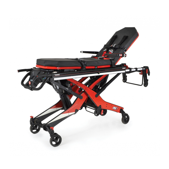
Page 12: In∫X Overview
3 - iN∫X OVERVIEW 3.1 Description WARNING The Ferno® iN∫X® Integrated Patient Transport & Loading System ™ Improper use of the iN∫X can cause injury. Use the iN∫X is an emergency patient-handling device designed to transport only for the purpose described in this manual. -
Page 13: General Specifications
Charger Output Up to 39.6 Volts DC, 2 Amps General specifications are rounded. Metric conversions are calculated before rounding. Ferno reserves the right to change specifications without notice. (for iN∫X LiFePO4 battery) Height: Distance from the ground to the patient surface. - Page 14 (Each Side) POSITION p.16 p.14 p.23 DISPLAY MATTRESS INDICATOR LIGHT (Each Side) TELESCOPING p.23 HANDLE (2) EXTEND AND RETRACT p.22 BUTTONS (2 Sets) DRIVE LIGHTS p.17 (Each Actuator) p.31 WHEEL LOCK (2) © Ferno-Washington, Inc. / 234-3622-06 / March 2019...
- Page 15 Overview Loading-End View SIDEARM p.27 (Each Side) PATIENT RESTRAINTS p.52 p.25 p.24 BACKREST SHOCK FRAME (Not Shown) p.26 SAFETY-BAR RELEASE p.26 TELESCOPING FRAME NON-POWERED OPERATION p.44 (Not Shown) © Ferno-Washington, Inc. / 234-3622-06 / March 2019...
-
Page 16: Features And Controls
(UV) light and pressure damage. This clear surface is normally invisible but may sometimes be seen as lines of clear "dots" when viewed at an angle. This is normal. © Ferno-Washington, Inc. / 234-3622-06 / March 2019... -
Page 17: Power Switch
After 10 minutes of non-use, the iN∫X will enter Sleep Mode to conserve power. See “Sleep Mode” on page 22. The iN∫LINE features a built-in Ferno® ICS® Integrated Charging System. With ICS, the iN∫X power switch can be left ON. The ICS disables the iN∫X powered mode and charges the battery. -
Page 18: Display Zones
See “Mode-Select Button” on page 23 and “Direct Power Modes” on page 42. If the countdown timer is allowed to expire, the iN∫X returns to its default operational mode and normal display screen. Countdown Timer © Ferno-Washington, Inc. / 234-3622-06 / March 2019... -
Page 19: Status Zone
The battery zone is illuminated whenever the power is ON or the iN∫X is connected to the powered ICS in the iN∫LINE. Charging Full Full Moderate Depleted (Flashing) in ICS in ICS © Ferno-Washington, Inc. / 234-3622-06 / March 2019... -
Page 20: Battery
Ferno Battery Carry Handle rechargeable battery. Outside the U.S.A. and Canada, contact the government of your country for recycling information. See “Recycling Notice” on page 55. © Ferno-Washington, Inc. / 234-3622-06 / March 2019... -
Page 21: Battery Charger
There are two ways to charge the battery: Secure the iN∫X in an iN∫LINE fastening system, or remove the battery from Indicator Lights the iN∫X and connect the battery directly to a Ferno battery charger. See “Charging the Battery” on page 54. -
Page 22: Extend And Retract Buttons
OFF. Mode, press . Note: Only the button will Press the button to activate the iN∫X. When the display is activate/wake up the iN∫X. active, press to extend or retract the legs. © Ferno-Washington, Inc. / 234-3622-06 / March 2019... -
Page 23: Mode-Select Button
If the line is visible on the ambulance floor, then the intermediate loading wheels and the majority of the load (the weight on the iN∫X) are also inside the ambulance. © Ferno-Washington, Inc. / 234-3622-06 / March 2019... -
Page 24: Shock Frame
Using both thumbs, press the shock frame control levers (Figure 18) to disengage the support bars, then lower the shock frame. Fasten and adjust the leg restraint. Control Lever (2) © Ferno-Washington, Inc. / 234-3622-06 / March 2019... -
Page 25: Backrest
Raise or lower the backrest to the desired position, then release the control handle to lock the backrest. Adjust the sidearms as needed for patient comfort. Adjust and fasten the patient restraints. Control Handle (2) © Ferno-Washington, Inc. / 234-3622-06 / March 2019... -
Page 26: Telescoping Frame
When standing at the patient left side, turn the bottom of the lever counter-clockwise. Safety-Bar When standing at the patient right side, turn Release Lever (2) the bottom of the lever clockwise. © Ferno-Washington, Inc. / 234-3622-06 / March 2019... -
Page 27: Sidearms
To store the sidearm: Rotate the sidearm toward the ● loading end of the iN∫X, aligned with the backrest. Press to Rotate Sidearm Slide to Swing Sidearm Outward © Ferno-Washington, Inc. / 234-3622-06 / March 2019... -
Page 28: Mattress
Confirm all eight hooks are engaged with the patient surface (Figure 27). To remove the mattress, slide your hand between the patient surface and mattress and guide the hooks through the patient surface. Control End Installed Hook © Ferno-Washington, Inc. / 234-3622-06 / March 2019... -
Page 29: Non-Powered Operation (Actuator-Release Handles)
For instructions on operating the iN∫X using the actuator- release handles, see the following sections: ● “Non-Powered Operation: Extending and Retracting” on page 44 “Non-Powered Operation: Loading” on page 46 ● “Non-Powered Operation: Unloading” on page 47 ● © Ferno-Washington, Inc. / 234-3622-06 / March 2019... -
Page 30: Oxygen Cylinder Holder
With one hand holding the oxygen bottle in place, firmly pull the loose end of the strap to cinch the fastening straps tight. Repeat to secure the second strap. Step 3 Fastening Strap (2) © Ferno-Washington, Inc. / 234-3622-06 / March 2019... -
Page 31: Patient Restraint System
Do not use wheel locks to slow an iN∫X while it is being rolled. Remain with the iN∫X and keep control of it at all times. ● Do not leave the patient unattended. Wheel Lock © Ferno-Washington, Inc. / 234-3622-06 / March 2019... -
Page 32: Using The In∫X
See “Status Zone” on page 19 and “Status Indicators” on page 63. An audible alarm beeps in a pattern corresponding to ● the priority of the status code. See “Audible Alarm” on page 19. © Ferno-Washington, Inc. / 234-3622-06 / March 2019... -
Page 33: Powered Extending/Retracting
Always keep both hands on the main frame and control the iN∫X. Buttons (2 sets) Extend Legs Retract Legs © Ferno-Washington, Inc. / 234-3622-06 / March 2019... -
Page 34: Transferring The Patient
Unlock the wheel locks. Press or until the iN∫X patient surface is at a suitable rolling height. See “Powered Extending/Retracting” on page 33 and “Rolling the iN∫X” on page © Ferno-Washington, Inc. / 234-3622-06 / March 2019... -
Page 35: Transferring The Patient: Chair Position
See “Powered Extending/Retracting” on page 33. 15. Make further adjustments to the backrest, shock frame, and/or sidearms as needed for patient comfort or medical care. 16. Unlock the wheel locks. Shock Frame © Ferno-Washington, Inc. / 234-3622-06 / March 2019... -
Page 36: Rolling The In∫X
Talk to the Patient Reassure the patient. Communicate before adjusting the height and during the loading and unloading processes. Full 360° Movement The iN∫X allows full maneuverability at any height, even when fully folded. © Ferno-Washington, Inc. / 234-3622-06 / March 2019... -
Page 37: One Operator, Empty In∫X
(Figure 37). Reminder: Do not lift. After the iN∫X is secured by the safety hook, allow the iN∫X legs and iN∫LINE to hold the weight. Raise and lower legs as needed. © Ferno-Washington, Inc. / 234-3622-06 / March 2019... -
Page 38: Loading The In∫X
No-Lift Loading/Unloading Do not lift the iN∫X off the ground when using power during the loading or unloading process. See “No-Lift Loading/Unloading” on page 9. © Ferno-Washington, Inc. / 234-3622-06 / March 2019... - Page 39 Use the Telescoping Handles Extend the telescoping handles to more easily maneuver the iN∫X into the iN∫LINE and reduce the amount of reaching required. Retract the handles before closing the ambulance rear doors. © Ferno-Washington, Inc. / 234-3622-06 / March 2019...
-
Page 40: Unloading The In∫X
When the red line is visible at the edge of the ambulance floor and the safety bar is engaged with the safety hook, the control- end legs are ready to be extended. © Ferno-Washington, Inc. / 234-3622-06 / March 2019... - Page 41 11. Control-end Operator: Press to lower the iN∫X to the factory-set transport height. Safety Hook Release Lever © Ferno-Washington, Inc. / 234-3622-06 / March 2019...
-
Page 42: Direct Power Modes
Use additional help if needed; see “Using Additional Help” on page 10. In each direct power mode, a countdown timer counts down from 15 seconds. If no further action is taken, the iN∫X reverts to its standard operating mode. © Ferno-Washington, Inc. / 234-3622-06 / March 2019... -
Page 43: Direct Power: Both Legs
Red wheels indicate that the iN∫X must not be rolled. ○ If the 15-second countdown timer expires, the iN∫X ○ returns to its standard operating mode. Countdown Timer © Ferno-Washington, Inc. / 234-3622-06 / March 2019... -
Page 44: Non-Powered Operation: Extending And Retracting
This ensures that you are holding the load. Non-Powered Recommendation When extending the iN∫X without power, Ferno recommends you begin at the loading end. Raise the loading-end legs first, then the control-end legs. © Ferno-Washington, Inc. / 234-3622-06 / March 2019... - Page 45 Non-Powered Recommendation When retracting the iN∫X without power, Ferno recommends you begin at the control end. Lower the control-end legs first, then the loading-end legs. Non-Powered Operation: Extending and Retracting (No Patient) © Ferno-Washington, Inc. / 234-3622-06 / March 2019...
-
Page 46: Non-Powered Operation: Loading
Use the locking clip (illustrated above) to hold the handle in the compressed state. This allows the handle operator to use both hands to maintain control of the iN∫X during non-powered loading and unloading. © Ferno-Washington, Inc. / 234-3622-06 / March 2019... -
Page 47: Non-Powered Operation: Unloading
Use the locking clip (illustrated above) to hold the handle in the compressed state. This allows the handle operator to use both hands to maintain control of the iN∫X during non-powered loading and unloading. © Ferno-Washington, Inc. / 234-3622-06 / March 2019... -
Page 48: Maintenance
If ● Is the iN∫X free of excessive wear? inspection shows damage or excessive wear, contact Ferno. ● Is all hardware securely in place? See “Ferno Customer Relations” on page 2. -
Page 49: Disinfecting Patient Restraints
“Mattress” on page 28. 6.7 Disinfecting the iN∫X Wipe all surfaces with disinfectant. Follow the disinfectant manufacturer’s instructions for application method and contact time. Inspect the iN∫X for damage as you disinfect it. © Ferno-Washington, Inc. / 234-3622-06 / March 2019... -
Page 50: Cleaning The In∫X
DO: Remove the battery. Cover the battery cable ● kPa). Ferno recommends you use a nozzle with a wide with a plastic bag. Close the bag with a wire tie or angle of spray (25° or 40°). Keep the nozzle at least 18 rubber band. -
Page 51: Lubricating The In∫X
Applying Lubricant Use a small amount of lubricant (one or two drops). Lubricate identical points on each side of the iN∫X. After applying lubricant, wipe off any excess. Lubricate (Both Sides, Both Ends) © Ferno-Washington, Inc. / 234-3622-06 / March 2019... -
Page 52: Patient Restraints
● Black-to-Black (Harness Chest Strap and Leg Restraint buckles) Plug Buckle Orientation Ferno recommends that you attach all patient restraints with the buckles Post at the same side for operator convenience and efficiency. © Ferno-Washington, Inc. / 234-3622-06 / March 2019... - Page 53 (or tang) through the loop. Pull the strap to tighten the strap against the restraint bracket (Figure 60). Plug Post Strap Keepers The shoulder straps have elastic bands to allow excess strap to be stored neatly. Restraint Bracket © Ferno-Washington, Inc. / 234-3622-06 / March 2019...
-
Page 54: Storing The In∫X
There are two ways to charge the battery: Secure the iN∫X in the iN∫LINE (equipped with the Integrated Charging System), Deeply-Discharged Battery or remove and connect the battery directly to a Ferno battery If the battery is deeply discharged, the charger. -
Page 55: Recycling Notice
U.S.A. AND CANADA "CALL2RECYCLE" 1.800.822.8837 Ferno is a partner with Call2Recycle Inc., a nonprofit corp- oration dedicated to helping consumers locate places to responsibly dispose of rechargeable batteries to meet all U.S. and Canadian requirements. -
Page 56: Adjusting The Backrest Control Handle Tension
Use a slotted screwdriver to slightly rotate the light unit inside the housing. Rotate and align one or both sides to form a straight line on the ground. Tighten the set screw(s). Step 4 © Ferno-Washington, Inc. / 234-3622-06 / March 2019... -
Page 57: Adjusting Tension Of The Actuator Release Handles
Repeat Step 2 and Step 3 to adjust the tension of each cable until proper handle function is achieved. If the cable cannot be adjusted satisfactorily, contact Ferno for repair. See “Parts and Service” on page 64. © Ferno-Washington, Inc. / 234-3622-06 / March 2019... -
Page 58: Adjusting The Oxygen Cylinder Holder
4 small, 4 rubber). Short Screw (4) Loctite® 242 - 4x Small Washer (4) Large Washer (4) Telescoping Frame Oxygen Cylinder Mount Assembly Rubber Washer (4) Hex Spacer(4) Properly Seated Oxygen Cylinder Mount © Ferno-Washington, Inc. / 234-3622-06 / March 2019... - Page 59 Use a 4 mm hex wrench to tighten the short screws. Outer Position Confirm the oxygen cylinder mount holds the cylinder securely. See “Oxygen Cylinder Holder” on page 30. Inner Position © Ferno-Washington, Inc. / 234-3622-06 / March 2019...
-
Page 60: Initial Setup
Keep accessory users' manuals with this manual for future reference. To order accessories, see “Accessories” on page 65. For additional free manuals, contact Ferno. See “Ferno Customer Relations” on page 2. 7.3 Charge and Install the Battery Charge the battery immediately upon receipt of the iN∫X... -
Page 61: Set The Loading Height
Test loading and unloading the iN∫X with the ambulance. Error Setting Loading Height No loading height will be set when the iN∫X is at the factory-set maximum transport height or maximum height. © Ferno-Washington, Inc. / 234-3622-06 / March 2019... -
Page 62: Technical Data
Ferno distributor or service center. battery connection. 8.2 iN∫X Battery Specifications The iN∫X battery (Figure 72) is a rechargeable, 36-Volt DC battery. The input port is proprietary to Ferno and is compatible only with the Ferno battery charger. Specifications: Ferno iN∫X Battery Battery Type... -
Page 63: Troubleshooting
2) A mechanical problem. 2) Call Ferno for service (page 2). Communication error. Use direct power to complete the patient transport, and call Ferno for service (page 2). Patient-surface has been above the maximum safe transport to lower the iN∫X to a safe transport height. -
Page 64: Parts And Service
Cable guide links, standard, iN∫X 090-5990 Cable guide links, bend in both directions, iN∫X 090-5991 To order Ferno parts, and for professional repair, contact your Charger adapter cable only, iN∫X 218-3008 Ferno distributor. Your distributor is the only agent authorized Mattress, iN∫X... -
Page 65: Accessories
Before placing the iN∫X in service, assign appropriate personnel to install any accessories shipped with the iN∫X. Keep accessory users’ manuals with this manual for future PacRac+ reference. For additional, free manuals, contact Ferno. See “Ferno Customer Relations” on page 2. iN∫X ACCESSORIES Description Kit Number iN∫X Charger for USA, w/adapter... -
Page 66: Training Record
TRAINING RECORD Training Method Trainer Date Printed Name Signature Initials Read Manual Video/Online Hands-On © Ferno-Washington, Inc. / 234-3622-06 / March 2019... -
Page 67: Maintenance Record
MAINTENANCE RECORD Date Maintenance Performed © Ferno-Washington, Inc. / 234-3622-06 / March 2019... - Page 68 © Ferno-Washington, Inc. / 234-3622-06 / March 2019...
Need help?
Do you have a question about the Integrated Patient Transport & Loading System iNX and is the answer not in the manual?
Questions and answers